Table of Contents
Advertisement
Quick Links
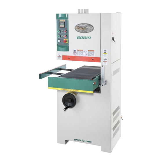
MODEL G0819
15" OPEN-END WIDE BELT SANDER
OWNER'S MANUAL
(For models manufactured since 09/16)
COPYRIGHT © MARCH, 2017 BY GRIZZLY INDUSTRIAL, INC.
WARNING: NO PORTION OF THIS MANUAL MAY BE REPRODUCED IN ANY SHAPE
OR FORM WITHOUT THE WRITTEN APPROVAL OF GRIZZLY INDUSTRIAL, INC.
#BLWK18649 PRINTED IN TAIWAN
V1.03.17
Advertisement
Table of Contents

Subscribe to Our Youtube Channel
Related Manuals for Grizzly G0819


Summary of Contents for Grizzly G0819
- Page 1 (For models manufactured since 09/16) COPYRIGHT © MARCH, 2017 BY GRIZZLY INDUSTRIAL, INC. WARNING: NO PORTION OF THIS MANUAL MAY BE REPRODUCED IN ANY SHAPE OR FORM WITHOUT THE WRITTEN APPROVAL OF GRIZZLY INDUSTRIAL, INC. #BLWK18649 PRINTED IN TAIWAN V1.03.17...
- Page 2 This manual provides critical safety instructions on the proper setup, operation, maintenance, and service of this machine/tool. Save this document, refer to it often, and use it to instruct other operators. Failure to read, understand and follow the instructions in this manual may result in fire or serious personal injury—including amputation, electrocution, or death.
-
Page 3: Table Of Contents
Table of Contents INTRODUCTION ..........2 SECTION 7: SERVICE ........40 Contact Info............ 2 Troubleshooting ........... 40 Manual Accuracy ........... 2 Adjusting Oscillation Speed/Timing ..... 43 Identification ........... 3 Servicing Platen ........... 44 Internal Features ..........4 Checking/Replacing Brake Pads ....45 Controls &... -
Page 4: Introduction
ID label (see below). This information is required for us to provide proper tech support, and it helps us determine if updated documenta- tion is available for your machine. Manufacture Date Serial Number Model G0819 (Mfd. Since 09/16) -
Page 5: Identification
Panel Panel Air Pressure Regulator/Filter, Table Elevation Electrical Panel ON/OFF Valve Handwheel Access Door Figure 1. Front and rear machine features. To reduce your risk of serious injury, read this entire manual BEFORE using machine. Model G0819 (Mfd. Since 09/16) -
Page 6: Internal Features
B. Left Limit Switch Pneumatic Cylinder K. Right Speed Control Knob C. Belt Tension Knob D. Platen Adjustment Lever Mirror M. Pneumatic Pulse-Jets E. Platen Adjustment Lock Lever N. Electronic Eye Sensor O. Right Limit Switch Model G0819 (Mfd. Since 09/16) -
Page 7: Controls & Components
OFF when pressed. Figure 6. Feed rate chain location. Conveyor Belt Stop Button: Turns feed N. Feed Rate Pressure Chain: Enables one of motor OFF when pressed. three feed rates: 16.4, 23, and 32.8 FPM. Model G0819 (Mfd. Since 09/16) -
Page 8: Belt Oscillation
Figure 9. Sanding belt tension knob location. S. Sanding Belt Tension Knob: Increases or decreases sanding belt tension. Rotate counterclockwise to remove old sanding belt. Rotate clockwise to tension new sanding belt. Model G0819 (Mfd. Since 09/16) -
Page 9: Machine Data Sheet
MACHINE DATA SHEET Customer Service #: (570) 546-9663 · To Order Call: (800) 523-4777 · Fax #: (800) 438-5901 MODEL G0819 15" OPEN‐END WIDE BELT SANDER Product Dimensions: Weight................................794 lbs. Width (side-to-side) x Depth (front-to-back) x Height............29-1/8 x 38-1/2 x 64-1/2 in. - Page 10 The information contained herein is deemed accurate as of 3/12/2017 and represents our most recent product specifications. Model G0819 PAGE 2 OF 3 Due to our ongoing improvement efforts, this information may not accurately describe items previously purchased. Model G0819 (Mfd. Since 09/16)
-
Page 11: Section 1: Safety
Everyday ery. Never operate under the influence of drugs or eyeglasses are NOT approved safety glasses. alcohol, when tired, or when distracted. Model G0819 (Mfd. Since 09/16) - Page 12 EXPERIENCING DIFFICULTIES. If at any time debris. Make sure they are properly installed, you experience difficulties performing the intend- undamaged, and working correctly BEFORE ed operation, stop using the machine! Contact our operating machine. Technical Support at (570) 546-9663. -10- Model G0819 (Mfd. Since 09/16)
-
Page 13: Additional Safety For Wide-Belt Sanders
Make sure machine is turned hands away from rotating sanding drum(s) during OFF, disconnected from power and air, and all operation. Never touch moving sandpaper. moving parts are completely stopped before changing belts, doing adjustments, or performing maintenance. -11- Model G0819 (Mfd. Since 09/16) -
Page 14: Section 2: Power Supply
To reduce the risk of these hazards, avoid over- loading the machine during operation and make sure it is connected to a power supply circuit that meets the specified circuit requirements. -12- Model G0819 (Mfd. Since 09/16) - Page 15 Conduit Conduit Extension Cords Ground Ground Since this machine must be permanently con- Figure 12. Typical setup of a permanently nected to the power supply, an extension cord connected machine. cannot be used. -13- Model G0819 (Mfd. Since 09/16)
-
Page 16: Section 3: Setup
IMPORTANT: Save all packaging materials until you are completely satisfied with the machine and have resolved any issues between Grizzly or the shipping agent. You MUST have the original pack- aging to file a freight claim. It is also extremely helpful if you need to return your machine later. -
Page 17: Inventory
1.5, 2, 2.5, 3, 4, 5, 5.5, 6, 8, 10mm ..1 Ea. packaging materials. Often, these items get lost in packaging materials while unpack- ing or they are pre-installed at the factory. Figure 13. Loose item inventory. -15- Model G0819 (Mfd. Since 09/16) -
Page 18: Cleanup
NOTICE Avoid chlorine-based solvents, such as acetone or brake parts cleaner, that may damage painted surfaces. Figure 15. T23692 Orange Power Degreaser. -16- Model G0819 (Mfd. Since 09/16) -
Page 19: Site Considerations
Wall = Electrical Connection Min. 30" for Maintenance Keep Outfeed Area Unobstructed 51" Min. 30" for Maintenance " Min. 30" Keep Loading Area Unobstructed for Maintenance Figure 16. Minimum working clearances. -17- Model G0819 (Mfd. Since 09/16) -
Page 20: Lifting & Placing
Remove shipping crate top and sides, then remove small components from shipping pallet. Move machine to its prepared location while it is still attached to shipping pallet. Figure 18. Lifting machine with forklift. -18- Model G0819 (Mfd. Since 09/16) -
Page 21: Anchoring To Floor
Figure 20. Dust hose attached to dust port. Figure 19. Popular method for anchoring Tug hose to make sure it does not come off. machinery to a concrete floor. Note: A tight fit is necessary for proper performance. -19- Model G0819 (Mfd. Since 09/16) -
Page 22: Air Connection
Air Connection Decrease PSI The Model G0819 uses compressed air to control Increase PSI belt tension and oscillation. Before starting the machine, connect it to a compressed air supply Lock Unlock that can deliver 75 PSI. Note: The machine will not run unless properly connected to an air supply. -
Page 23: Connecting To Power Source
R and S terminals shown in Figure 24. Figure 26. Disconnecting power from machine. Incoming Power Ground Terminals Terminal Figure 24. Terminal locations to connect incoming power wires and ground wire. -21- Model G0819 (Mfd. Since 09/16) -
Page 24: Test Run
Twist Emergency Stop button clockwise until it springs out (see Figure 28). This resets switch so machine can start. Figure 28. Resetting Emergency Stop button. -22- Model G0819 (Mfd. Since 09/16) - Page 25 Congratulations! The Test Run is complete. 11. Reset Emergency Stop button. -23- Model G0819 (Mfd. Since 09/16)
-
Page 26: Section 4: Operations
Regardless of the content in this sec- 11. Changes sandpaper to a finer grit. tion, Grizzly Industrial will not be held liable for accidents caused by lack of training. 12. Repeats Steps 8–11 as needed, turns sand- er OFF, and disconnects it from power. -
Page 27: Workpiece Inspection
180-Grit ............. 1 tious backer board, etc. The Model G0819 only accepts 16" wide by Sanding improper materials increases the 48" long sanding belts. For additional sanding risk of respiratory harm to the operator and... - Page 28 With hands clear of all moving parts, tension belt by rotating belt tension knob to "Tension" (see Figure 30), then close and position secure upper left access door. Release Position Tension Position Figure 31. Sanding belt tension knob positions. -26- Model G0819 (Mfd. Since 09/16)
-
Page 29: Adjusting Platen
Due to its cushioned- graphite cloth and felt have worn out and construction, the platen is less likely to leave belt- need to be replaced immediately. splice or chatter marks. -27- Model G0819 (Mfd. Since 09/16) -
Page 30: Sanding Tips
(aka "Butt Feeding"). • Feed boards into the machine at different points on the conveyor to maximize sandpa- per life and prevent uneven belt wear. -28- Model G0819 (Mfd. Since 09/16) -
Page 31: Amp Load Meter
Keep amp draw within GREEN load range shown on the AMP LOAD CHART. If you operate machine in RED load range motor damage may occur and will not be covered under warranty. -29- Model G0819 (Mfd. Since 09/16) -
Page 32: Sanding Workpieces
Down 1mm load meter indicates motor overload, slightly lower the table with the handwheel or reduce the feed *These numbers assume the platen is raised up rate (refer to Page 31). during the sanding pass. -30- Model G0819 (Mfd. Since 09/16) -
Page 33: Changing Feed Rate
This means you need to use shallower sanding depths at higher feed rates to avoid over- loading the sanding motor. Tools Needed Hex Wrench 6mm ..........1 Hex Wrench 12mm ..........1 -31- Model G0819 (Mfd. Since 09/16) - Page 34 Loosen tension screw from Step 3, move motor down to re-tension chain, then tighten tension screw motor position and pivot screw to secure (see Figure 39 on Page 31). Re-install chain cover and cap screw removed during Step 2. -32- Model G0819 (Mfd. Since 09/16)
-
Page 35: Section 5: Accessories
H4173—60-Grit cause machine to malfunction, resulting in H4174—80-Grit serious personal injury or machine damage. H4175—100-Grit To reduce this risk, only install accessories H4176—120-Grit recommended for this machine by Grizzly. H4177—150-Grit H8792—60-Grit (5-Pk.) H8793—80-Grit (5-Pk.) NOTICE H8794—100-Grit (5-Pk.) H8795—120-Grit (5-Pk.) Refer to our website or latest catalog for additional recommended accessories. - Page 36 Features thumb roll and stainless steel construc- tion. Range: 0-6", 0-150mm. Resolution: 0.0005", 0.01mm, ⁄ ". Figure 45. Pro-Stik cleaning pad. Figure 47. H7978 fractional digital caliper. www.grizzly.com 1-800-523-4777 order online at or call -34- Model G0819 (Mfd. Since 09/16)
- Page 37 A must have for beginners! Figure 48. G0777 Ultra-Quiet Cyclone Dust Collector. Figure 50. Dust Collection Basics handbook. www.grizzly.com 1-800-523-4777 order online at or call -35- Model G0819 (Mfd. Since 09/16)
- Page 38 ⁄ " thick cushion. Beveled edges minimize tripping. Black. Made in the U.S.A. Figure 52. H4228 Anti-fatigue Matt. www.grizzly.com 1-800-523-4777 order online at or call -36- Model G0819 (Mfd. Since 09/16)
-
Page 39: Section 6: Maintenance
To reduce risk of shock or accidental startup, always disconnect machine from power before adjustments, Cleaning the Model G0819 is relatively easy. maintenance, or service. Vacuum excess wood chips and sawdust, and wipe off the remaining dust with a dry cloth. If any... - Page 40 (1 of 4) (1 of 4) Figure 56. Location of table elevation leadscrews, chain, and sprockets (lower left access panel removed). Figure 55. Locations of conveyor belt roller axle grease fittings (chain cover removed for access). -38- Model G0819 (Mfd. Since 09/16)
-
Page 41: Cleaning Sanding Belt
• Make sure lines are not clogged. Remove a questionable line and blow through it as a test. -39- Model G0819 (Mfd. Since 09/16) -
Page 42: Section 7: Service
7. Motor bearings at fault. 7. Test by rotating shaft; rotational grinding/loose shaft requires bearing replacement. 8. Centrifugal switch is at fault. 8. Replace. 9. Conveyor belt gearbox at fault. 9. Rebuild gearbox for bad gear(s)/bearing(s). -40- Model G0819 (Mfd. Since 09/16) - Page 43 55). positions (Page 1. Clean/replace sanding belt (Pages 26 & 39). Poor, non- 1. Sanding belt worn/clogged. aggressive 2. Sanding belt grit too fine for particular job. 2. Replace with coarser grit. sanding results. -41- Model G0819 (Mfd. Since 09/16)
- Page 44 2. Water filter/trap drain cock left open. 2. Ensure water filter/trap drain cock is tight. 3. Air line ruptured or air leaking at a connection 3. Find source of sound and determine likely cause based point. on what you see. -42- Model G0819 (Mfd. Since 09/16)
-
Page 45: Adjusting Oscillation Speed/Timing
Repeat Steps 3–4 for other speed control knob, making sure to adjust both knobs equally. Connect machine to power and test oscilla- tion speed, then repeat Steps 1–5 as needed until you are satisfied. -43- Model G0819 (Mfd. Since 09/16) -
Page 46: Servicing Platen
Use a putty knife to scrape off any remaining felt and glue. Platen Use spray adhesive or contact cement to secure new felt pad to platen. Steps 6–7 Replacing Graphite Follow Pad. Figure 61. Example of removing platen. -44- Model G0819 (Mfd. Since 09/16) -
Page 47: Checking/Replacing Brake Pads
Checking and replacing these is a simple pro- cedure that can be done in the shop, with the exception of having the rotor resurfaced on Air Supply lathe. Contact Grizzly Customer Service at Disconnected (570) 546-9963 to order replacement brake pads (Part #P08190212). - Page 48 Step 4 to measure brake pads. Right Brake Pad Mounting Bolt (1 of 2) Figure 70. Location of right brake pad and Figure 67. Location of disc brake assembly mounting cap screw. mounting bolts (1 of 2 shown). -46- Model G0819 (Mfd. Since 09/16)
- Page 49 12. Re-install lower right access panel. 13. Reconnect air line. 14. Start sander and test Emergency Stop sys- tem to make sure brake works. Figure 72. Location of disc brake assembly compression spring and bushing. -47- Model G0819 (Mfd. Since 09/16)
-
Page 50: Checking/Adjusting Table Parallelism
(approx. 4" long) and record measurement. Leadscrew Flanges Figure 74. Table elevation leadscrew flanges located on underside of table. Table Elevation Sprockets (2 of 4) Figure 75. Location of table elevation sprockets (2 of 4 shown). -48- Model G0819 (Mfd. Since 09/16) - Page 51 Frame Do Not Measure from Safety Plate Figure 79. Front measurement locations for checking table parallelism. Figure 77. Position of wood block on conveyor table. -49- Model G0819 (Mfd. Since 09/16)
- Page 52 11. Carefully rotate sprocket just enough to posi- adjustment. tion next tooth at marked location from Step 7, then fit chain around sprocket again. Rotate sprocket counterclockwise to raise table; rotate sprocket clockwise to lower table. -50- Model G0819 (Mfd. Since 09/16)
-
Page 53: Checking/Adjusting Pressure Rollers
V-belts (refer to Page 54 for more information). Move sanding drum by hand, and manually raise table until you hear sandpaper just con- tact surface of wood. DO NOT continue to raise table beyond this point. -51- Model G0819 (Mfd. Since 09/16) - Page 54 (see Figure 83). Adjustment Bolt Jam Nuts Adjustment Bolt Right Side Infeed Roller Outfeed Roller Adjustment Bolt Jam Nuts Adjustment Bolt Outfeed Roller Left Side Infeed Roller Figure 83. Locations of pressure roller adjust- ment components. -52- Model G0819 (Mfd. Since 09/16)
-
Page 55: Checking/Adjusting V-Belt Tension
— If there is not approximately ⁄ "– ⁄ " deflec- tion when V-belts are pushed with mod- erate pressure, V-belts are not properly tensioned. Proceed to Step 4. -53- Model G0819 (Mfd. Since 09/16) -
Page 56: Changing V-Belts
Re-install V-belt cover from Step 3, close and Sanding Drum secure upper right access door, and re-install Pulley lower right access panel. V-Belts Figure 87. V-belt cover removed to expose V-belts and sanding drum pulley. -54- Model G0819 (Mfd. Since 09/16) -
Page 57: Adjusting Pneumatic Pulse Jets
Figure 89. Pulse jets aiming at sensor and Figure 90. Location of conveyor belt adjustment mirror (belt removed for clarity). bolts (1 of 2 shown). Tighten hex nuts to secure pulse jets, then close right access door. -55- Model G0819 (Mfd. Since 09/16) -
Page 58: Adjusting Conveyor Belt Tracking
— If conveyor belt is tracking to the right, Figure 92. Scale pointer screws location. rotate the right adjustment bolt (see Figure 90) clockwise. — If conveyor belt is tracking to the left, rotate the left adjustment bolt (see Figure 90) clockwise. -56- Model G0819 (Mfd. Since 09/16) -
Page 59: Sanding Belt Limit Switches
⁄ " apart. Location Tighten bolt and repeat adjustment with other side if necessary. Start machine and make sure it is working properly. Figure 93. Tracking limit switch adjustment bolt (right side shown). -57- Model G0819 (Mfd. Since 09/16) -
Page 60: Replacing Conveyor Belt
16. Re-install lower left access panel. remove sprockets. Remove conveyor motor and motor bracket. 17. Start conveyor motor and turn conveyor tracking bolts as required until conveyor belt tracks straight without loading up on one side of table. -58- Model G0819 (Mfd. Since 09/16) - Page 61 WARNING DISCONNECT Table POWER! Extension Access Panel Conveyor Motor & Gearbox Left Roller Support Conveyor Table Assembly Infeed Drum Emergency Stop Plate Conveyor Belt Tracking 9–10 Adjustment Bolts Figure 95. Conveyor belt removal sequence. -59- Model G0819 (Mfd. Since 09/16)
-
Page 62: Air System Diagram
Air System Diagram Air Solenoid #1 Brake Air Solenoid #2 Air Piston Air Cyclinder Switch Air Cyclinder Air Regulator Air Line IN -60- Model G0819 (Mfd. Since 09/16) -
Page 63: Section 8: Wiring
Technical Support at (570) 546-9663. The photos and diagrams included in this section are best viewed in color. You can view these pages in color at www.grizzly.com. -61- Model G0819 (Mfd. Since 09/16) -
Page 64: Component Locations
Air Cylinder Page 60 Limit Switch Page 64 Electrical Panel Page 64 Limit Switch Page 64 Feed Motor Page 67 Ground 220 VAC DISCONNECT SWITCH (as recommended ) READ ELECTRICAL SAFETY -62- Model G0819 (Mfd. Since 09/16) ON PAGE 61! -
Page 65: Electrical Cabinet
Electrical Cabinet Amperage Gauge Fuse Fuse Overload Contactor Relay Relay Relay Contactor & Overload Relay Terminal Figure 996. Electrical cabinet wiring. Limit Switch Solenoids Figure 97. Pneumatic solenoids. READ ELECTRICAL SAFETY -63- Model G0819 (Mfd. Since 09/16) ON PAGE 61! - Page 66 -64- Model G0819 (Mfd. Since 09/16)
-
Page 67: Control Panel Wiring
Figure 98. Control panel wiring. INDICATOR LIGHT To Electrical Box BELT LIMIT EMERGENCY STOP SWITCHES LIMIT SWITCH Figure 99. E-Stop panel limit switch. To Electrical Box To Electrical Box Figure 100. Belt limit switch (1 of 2). -65- Model G0819 (Mfd. Since 09/16) -
Page 68: Control Panel Wiring Schematic
Control Panel Wiring Schematic Incoming Power Supply Main Motor Motor Feed Belt Motor Motor Power Indicator Amp Meter Sanding Belt Oscillation Control E-Stop Brake Emergency Stop Sanding Belt Conveyor Belt -66- Model G0819 (Mfd. Since 09/16) -
Page 69: Motor Wiring
600MFD 250V Motor Run Capacitor 30MFD 300V To Electrical Box U1-1 U2-4 V2-5 V1-2 To Motor W1-3 Feed W1-6 Motor Run Capacitor 40MFD 350V Figure 101. Main motor wiring. Figure 102. Feed motor wiring. -67- Model G0819 (Mfd. Since 09/16) -
Page 70: Section 9: Parts
SANDING BELT 16" X 48" #180 We do our best to stock replacement parts when possible, but we cannot guarantee that all parts shown are available for purchase. Call (800) 523-4777 or visit www.grizzly.com/ parts to check for availability. -68- Model G0819 (Mfd. Since 09/16) - Page 71 CAP SCREW 5/16-18 X 1-1/4 P08190210 LOCK WASHER 3/8 P08190112 LOCK WASHER 5/16 P08190211 HEX NUT 3/8-16 P08190113 KEY 8 X 7 X 55 P08190212 BRAKE LINING P08190114 HEX BOLT 5/16-18 X 1 P08190213 BRAKE BRACKET GASKET -69- Model G0819 (Mfd. Since 09/16)
- Page 72 P08190608 HEX NUT 5/16-18 P08190504 BEARING CAP (B) P08190609 LOCK WASHER 5/16 P08190505 PHLP HD SCR 1/4-20 X 3/4 P08190610 HEX BOLT 5/16-18 X 5/8 P08190506 WORM SHAFT P08190611 HEX BOLT 3/8-16 P08190507 BALL BEARING 6002-2RS -70- Model G0819 (Mfd. Since 09/16)
- Page 73 723-7 P08190723-7 MOTOR CORD 18G 3W 72" P08190812 TABLE EXTENSION SUPPORT 723-8 P08190723-8 CONTACT PLATE P08190813 TABLE EXTENSION COVER 723-9 P08190723-9 CENTRIFUGAL SWITCH P08190814 FLAT HD SCR M5-.8 X 8 P08190724 FEED MOTOR SPROCKET -71- Model G0819 (Mfd. Since 09/16)
- Page 74 1004 P08190907 HEX NUT 5/16-18 P08191005 SET SCREW 1/4-20 X 3/8 1005 P08190908 HEX BOLT 5/16-18 X 3/4 P08191006 HEX BOLT M6-1 X 16 1006 P08190909 LOCK WASHER 5/16 P08191007 LOCK WASHER 6MM 1007 -72- Model G0819 (Mfd. Since 09/16)
- Page 75 1301 P08191301 PLATEN MOUNTING BLOCK 1325 P08191325 FLAT WASHER 5/16 1302 P08191302 PLATEN HOUSING 1326 P08191326 HEX NUT 5/16-18 1303 P08191303 FELT PAD 1327 P08191327 HEX BOLT 5/16-18 X 3/4 1304 P08191304 GRAPHITE PAD -73- Model G0819 (Mfd. Since 09/16)
- Page 76 P08191512 HEX NUT 3/8-16 1420 P08191420 SENSOR MIRROR 1513 P08191513 HEX BOLT 3/8-16 X 1-1/4 1421 P08191421 FLAT WASHER 5/16 1514 P08191514 HEX BOLT 3/8-16 X 2 1422 P08191422 HEX BOLT 5/16-18 X 1/2 -74- Model G0819 (Mfd. Since 09/16)
-
Page 77: Frame Covers And Doors
UPPER FRAME, LEFT DOOR 1612 P08191612 THICKNESS SCALE 1605 P08191605 UPPER FRAME, RIGHT DOOR 1613 P08191613 THICKNESS SCALE INDICATOR 1606 P08191606 DOOR LOCK (SQUARE KEY) 1614 P08191614 LOWER FRAME, LEFT DOOR 1609 P08191609 LOWER FRAME, RIGHT DOOR -75- Model G0819 (Mfd. Since 09/16) -
Page 78: Electrical Components
1721 P08191721 PHLP HD SCR 1/4-20 X 1/2 1747 P08191747 BUTTON SWITCH, YK 10A 250V RED 1722 P08191722 STRAIN RELIEF 1/2" TYPE-3 1748 P08191748 BUTTON SWITCH, YK 10A 250V GRN 1723 P08191723 STRAIN RELIEF 3/4" TYPE-1 -76- Model G0819 (Mfd. Since 09/16) -
Page 79: Belt Oscillator Pneumatics
1836 P08191836 CONNECTOR 1/8 X 4 W/CASING 1815 P08191815 ELBOW 1/4T X 1/4T 1837 P08191837 CONNECTOR 1/4N X 1/8T 1817 P08191817 THROTTLE VALVE 1/8 1838 P08191838 FLAT WASHER #10 1820 P08191820 CONNECTOR 1/4N X 3/8T -77- Model G0819 (Mfd. Since 09/16) -
Page 80: Labels & Cosmetics
AMPERAGE LOAD CHART LABEL 1906 P08191906 GLASSES/RESPIRATOR LABEL 1914 P08191914 ELECTRICITY LABEL 1907 P08191907 PINCH HAZARD LABEL 1915 P08191915 TOUCH-UP PAINT, GRIZZLY GREEN 1908 P08191908 PLATE POSITION NOTICE LABEL 1916 P08191916 TOUCH-UP PAINT, GRIZZLY PUTTY -78- Model G0819 (Mfd. Since 09/16) - Page 81 Would you recommend Grizzly Industrial to a friend? _____ Yes _____No Would you allow us to use your name as a reference for Grizzly customers in your area? Note: We never use names more than 3 times. _____ Yes _____No 10.
- Page 82 FOLD ALONG DOTTED LINE Place Stamp Here GRIZZLY INDUSTRIAL, INC. P.O. BOX 2069 BELLINGHAM, WA 98227-2069 FOLD ALONG DOTTED LINE Send a Grizzly Catalog to a friend: Name_______________________________ Street_______________________________ City______________State______Zip______ TAPE ALONG EDGES--PLEASE DO NOT STAPLE...
-
Page 83: Warranty & Returns
WARRANTY & RETURNS Grizzly Industrial, Inc. warrants every product it sells for a period of 1 year to the original purchaser from the date of purchase. This warranty does not apply to defects due directly or indirectly to misuse, abuse, negligence, accidents, repairs or alterations or lack of maintenance.
Need help?
Do you have a question about the G0819 and is the answer not in the manual?
Questions and answers