
Related Manuals for ADLINK Technology DLAP-8000 Series


Summary of Contents for ADLINK Technology DLAP-8000 Series
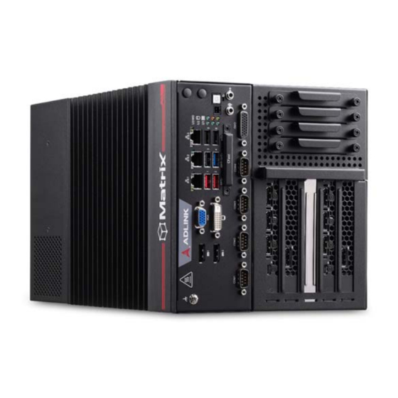
- Page 1 DLAP-8000 Series High Performance 9th Generation Intel® Xeon®/Core™ i7/i5/i3 Processor Edge Workstation Computer User’s Manual Manual Rev.: Nov. 18, 2020 Revision Date: 50-1Z238-1000 Part No: Leading EDGE COMPUTING...
- Page 2 Leading EDGE COMPUTING Revision History Revision Release Date Description of Change(s) Nov. 18, 2020 Initial release...
- Page 3 DLAP-8000 Preface Copyright © 2020 ADLINK Technology Inc. This document contains proprietary information protected by copy- right. All rights are reserved. No part of this manual may be repro- duced by any mechanical, electronic, or other means in any form without prior written permission of the manufacturer.
- Page 4 Leading EDGE COMPUTING California Proposition 65 Warning WARNING: This product can expose you to chemicals including acrylamide, arsenic, benzene, cadmium, Tris(1,3-dichloro-2-propyl) phosphate (TDCPP), 1,4- Dioxane, formaldehyde, lead, DEHP, styrene, DINP, BBP, PVC, and vinyl materials, which are known to the State of California to cause cancer, and acrylamide, benzene, cadmium, lead, mercury, phthalates, toluene, DEHP, DIDP, DnHP, DBP, BBP, PVC, and vinyl materials, which are known to the State of California to cause...
-
Page 5: Table Of Contents
DLAP-8000 Table of Contents Preface ..................iii List of Tables................. vii List of Figures ................ ix 1 Introduction ................ 1 Overview................1 Features................1 Packing List ................. 2 2 Specifications ..............3 DLAP-800X/DLAP-8001/DLAP-8002/DLAP-8003 ....3 DLAP-8000 Functional Block Diagram ........ 5 Display Options.............. - Page 6 Leading EDGE COMPUTING Chipset................57 Security ................72 Boot ................... 74 Save & Exit ................ 76 C Appendix: Watchdog Timer (WDT) Function Library ..............79 WDT with API/Windows ............. 79 WDT with DOS/Linux ............82 D Appendix: Digital Input/Output Function Library ..............85 Important Safety Instructions..........
-
Page 7: List Of Tables
DLAP-8000 List of Tables Table 2-1: Max. Available Resolution Display Configurations..6 Table 3-1: Front Panel I/O Legend ..........11 Table 3-2: LED Indicators ............12 Table 3-3: DisplayPort Pin Definition ......... 13 Table 3-4: Applicable Cable Types..........14 Table 3-5: Digital Input/Output Connector Pin Definition ... - Page 8 Leading EDGE COMPUTING This page intentionally left blank. viii List of Tables...
-
Page 9: List Of Figures
DLAP-8000 List of Figures Figure 2-1: DLAP-8000 Front View (including wall-mount brackets) . 7 Figure 2-2: DLAP-8000 Left Side View ..........8 Figure 2-3: DLAP-8000 Right Side View..........9 Figure 2-4: DLAP-8000 Top View ............ 10 Figure 3-1: Front Panel I/O .............. 11 Figure 3-2: DisplayPort Connector Pin Definition...... - Page 10 Leading EDGE COMPUTING This page intentionally left blank. List of Figures...
-
Page 11: Introduction
DLAP-8000 Introduction 1.1 Overview ADLINK’s DLAP-8000 Series of industrial GPU workstations, ® ™ ® incorporating Intel Core i7/i5/i3 and processors, provides Xeon five PCIe slot supporting two FHFL PEG cards, one mini-PCIe slot and single-side access for I/O ports, optimizing easy maintenance in industrial automation environments. -
Page 12: Packing List
Leading EDGE COMPUTING Flexible and powerful PCIe expansions via backplane: 2x FHFL PCI Express cards (e.g. Quadro RTX 8000) accommodation w/ AUX power inlets PCIe x8, x1, x4, x8, and x4 signals with physical x16, x4, x8, x16, and x8 slots Optional AC or DC SKUs in power inputs 1.3 Packing List Before unpacking, check the shipping carton for any damage. -
Page 13: Specifications
DLAP-8000 Specifications 2.1 DLAP-800X/DLAP-8001/DLAP-8002/DLAP-8003 DLAP-800X DLAP-8001 DLAP-8002 DLAP-8003 System Core Intel® Xeon® Intel® Core™ Intel® Core™ Intel® Core™ Processor E-2278GE 80W i7-9700TE 35W i5-9500TE 35W i3-9100TE 35W Core # Base Freq. 3.3 GHz 2.6 GHz 2.2 GHz 2.2 GHz MAX Turbo 4.7 GHz 4.4 GHz 3.6 GHz... - Page 14 Leading EDGE COMPUTING DLAP-800X DLAP-8001 DLAP-8002 DLAP-8003 Physical Dimensions 210 (W) x 210 (D) x 350 (H) mm (8.27" x 8.27” x 13.8”) DC mode: 7 kg (15.43 lbs) Weight AC mode: 9 kg (19.84 lbs) Mounting Wall mount Power Supply DC Input 24V DC AC Input...
-
Page 15: Dlap-8000 Functional Block Diagram
DLAP-8000 2.2 DLAP-8000 Functional Block Diagram DDI1 DDR4 SO-DIMM DP CN DDI2 DDR4 SO-DIMM DP CN Intel DDI3 Processor DP to DVI LS DVI CN PTN3360 PEG (x16) eDP to VGA PTN3355 Intel PHY PCIe PCIe x4 (C 246 support) RJ45 CN I219 Board... -
Page 16: Display Options
Leading EDGE COMPUTING 2.3 Display Options With computing and graphic performance enhancement from its 8th & 9th Generation Intel processors, the DLAP-8000 controller can support or three independent displays, with configurations as follows. Port Resolution DisplayPort1 4096x2304@60Hz Display Option 1 DisplayPort2 4096x2304@60Hz Display Option 2... -
Page 17: Mechanical Dimensions
DLAP-8000 2.4 Mechanical Dimensions units: mm Figure 2-1: DLAP-8000 Front View (including wall-mount brackets) Specifications... -
Page 18: Figure 2-2: Dlap-8000 Left Side View
Leading EDGE COMPUTING units: mm Figure 2-2: DLAP-8000 Left Side View Specifications... -
Page 19: Figure 2-3: Dlap-8000 Right Side View
DLAP-8000 units: mm Figure 2-3: DLAP-8000 Right Side View Specifications... -
Page 20: Figure 2-4: Dlap-8000 Top View
Leading EDGE COMPUTING units: mm Figure 2-4: DLAP-8000 Top View Specifications... -
Page 21: System Layout
DLAP-8000 System Layout 3.1 Front Panel The DLAP-8000 Series provides the following front panel access features. G H I J K Figure 3-1: Front Panel I/O DC Power Input Extend Power Button DisplayPort x2 J Power Button DVI-D K Reset Button L Audio (Mic, Phones/Speaker) USB 3.1 Type-A x3 (1, 2, 4) -
Page 22: Table 3-2: Led Indicators
Leading EDGE COMPUTING 3.1.1 Power Button The power button is a non-latched push button with a blue LED indicator. System is turned on when the button is depressed, and the power LED lights. If the system hangs, depress the button for 5 seconds to turn off the system completely. -
Page 23: Table 3-3: Displayport Pin Definition
DLAP-8000 3.1.5 PCI Express x4 Slot One PCI Express x4 (data bus x1) slot supports expansion with standard PCIe Gen3 cards. 3.1.6 Reset Button The reset button executes a hard reset for the DLAP-8000. 3.1.7 DisplayPort Connectors Two DisplayPort connectors on the front panel can connect to VGA, DVI, HDMI and DisplayPort monitors via DisplayPort to VGA adapter cable, DisplayPort to DVI adapter cable, or DisplayPort to HDMI adapter cable and DisplayPort cable. -
Page 24: Table 3-4: Applicable Cable Types
Leading EDGE COMPUTING Description 30-01119-0020 Passive DisplayPort to HDMI adapter cable 30-01120-0020 Passive DisplayPort to DVI adapter cable 30-01121-0020 Passive DisplayPort to VGA adapter cable 30-01157-0020 Active DisplayPort to DVI adapter cable Table 3-4: Applicable Cable Types 3.1.8 Digital I/O Connector The DLAP-8000 provides 8 channels of non-isolation digital input and 8 channels of non-isolation digital output circuits, with spec and circuits as follows. -
Page 25: Table 3-5: Digital Input/Output Connector Pin Definition
DLAP-8000 Signal Signal Signal Signal Table 3-5: Digital Input/Output Connector Pin Definition Figure 3-4: Digital Input Circuit System Layout... -
Page 26: Table 3-6: Dvi-D Connector Pin Definition
Leading EDGE COMPUTING Figure 3-5: Digital Output Circuit 3.1.9 DVI-D Connector The DLAP-8000 provides one DVI-D connector for connection to an external monitor. Figure 3-6: DVI-D Connector Pin Definition Signal Signal Signal DVIdata 2- DVIdata 1- DVIdata 0- DVIdata 2+ DVIdata 1+ DVIdata 0+ DVIDC clock... -
Page 27: Table 3-7: Vga Connector Pin Definition
DLAP-8000 3.1.10 VGA Connector Figure 3-7: VGA Connector Pin Definition Signal G_VGA_R G_VGA_G G_VGA_B CRT_DDAT_CN G_VGA_HSYNC G_VGA_VSYNC CRT_DCLK_CN Table 3-7: VGA Connector Pin Definition 3.1.11 USB 2.0 Ports The DLAP-8000 provides three USB 2.0 ports supporting Type A USB connection on the front panel. All USB ports are compatible with high-speed, full-speed and low-speed USB devices. -
Page 28: Figure 3-8: Ethernet Port And Leds
Leading EDGE COMPUTING 3.1.12 USB 3.1 Ports The DLAP-8000 provides two USB 3.1 Gen2 and one USB 3.1 Gen1 ports supporting Type A USB 3.1 connection on the front panel. All USB 3.1 ports are compatible with SuperSpeed Gen2, high-speed, full-speed, and low-speed USB devices. The H310 SKU supports three USB 3.1 Gen1 ports only. -
Page 29: Table 3-8: Ethernet Port Pin Definition
DLAP-8000 10BASE-T/100BASE-TX 1000BASE-T LAN_TX0+ LAN_TX0- LAN_TX1+ — LAN_TX2+ — LAN_TX2- LAN_TX1- — LAN_TX3+ — LAN_TX3- Table 3-8: Ethernet Port Pin Definition LED Color Status Description Ethernet port is disconnected. Yellow Ethernet port is connected with no activity. Flashing Ethernet port is connected and active. Table 3-9: Active/Link LED Indicators LED Color Status... -
Page 30: Table 3-11: Dc Power Input Pin Definition
Leading EDGE COMPUTING 3.1.14 DC Power Input Figure 3-9: DC Power Input Signal V+ (DC_IN) V- (DGND) Table 3-11: DC Power Input Pin Definition Figure 3-10: Backplane DC Power Input Signal Table 3-12: Backplane DC Power Input Pin Definition System Layout... - Page 31 DLAP-8000 The backplane connector supports a backplane power supply to provide PEG card power in a DC mode system. It can pro- vide 24V and 20A for the backplane. It is recommended to use NOTE: NOTE: the same power supply as the motherboard. Refer to Section 4.1: Attach DC Power Connector on page 31 to install the DC Power Connector to the DC Power Input.
-
Page 32: Table 3-13: D-Sub 9-Pin Signal Function Of Com Ports
Leading EDGE COMPUTING 3.1.15 COM Port Connectors The DLAP-8000 provides four COM ports through D-sub 9-pin connectors. The COM1 & COM2 ports support RS-232/422/485 modes by BIOS setting, while COM3 and COM4 support only RS- 232. Figure 3-11: COM Port Pin Definition Signal Name RS-232 RS-422... -
Page 33: Figure 3-12: Cfast Host Slot
DLAP-8000 3.1.16 CFast Host Slot The DLAP-8000 is equipped with a Type II Push-Push CFast host slot on the front panel, by SATA interface. Data transfer rates up to 3.0Gb/s (300MB/s) are supported. The host SATA controller provides a legacy operating mode using I/O space, and an AHCI operating mode using memory space. -
Page 34: Internal I/O Connectors
Leading EDGE COMPUTING 3.2 Internal I/O Connectors 3.2.1 Mainboard Connector Locations Figure 3-13: Mainboard Connectors System Layout... -
Page 35: Table 3-14: Mainboard Connector Legend
DLAP-8000 Smart Fan SATA USB 2.0 dongle SATA DDR4 SODIMM PCIe x16 slot for PEG and SATA Wafer for GPS external power SIM for M.2 SIM for Mini PCIe Mini PCIe Wafer for I2C sensor Wafer for Speaker Wafer for COM x2, DI x8, DO x8 Mic in and Line out Wafer for COM x4 Wafer for I2C sensor Internal Power button... -
Page 36: Table 3-15: 5-Slot Backplane Board Connector Legend
Leading EDGE COMPUTING 3.2.2 5-slot Backplane Connector Locations Figure 3-14: 5-slot Backplane Board Connectors PCIe x16 (data bus x8) PCIe x4 (data bus x1) PCIe x8 (data bus x4) PCIe x16 (data bus x8) PCIe x8 (data bus x4) SATA USB 2.0 12V output 12V output... -
Page 37: Table 3-16: Gps Module Power Header Pin Definition
DLAP-8000 3.2.3 GPS Module Power Headers Power supply via cable for Mini PCIe GPS module cards (5V). Figure 3-15: GPS Module Power Header Pin Definition Signal +5V_GPS Table 3-16: GPS Module Power Header Pin Definition 3.2.4 USB 2.0 Connector One USB 2.0 Type-A connector is provided on the mainboard for internal USB dongle, with another on the backplane board. -
Page 38: Table 3-17: 12V Fan Connector Pin Definition
Leading EDGE COMPUTING 3.2.7 12V Fan Connector DC 12V fan module power supply is provided through the connec- tor, to which the optional fan module connects when installed in the chassis. Figure 3-16: 12V Fan Connector Pin Definition Signal FAN_GND P_+12V_FAN SIO_FAN_IN SIO_FAN_OUT... -
Page 39: Table 3-18: Pwr/Reset Header Pin Definition
DLAP-8000 3.2.9 Extended PWR/RESET Header An internal header is provided for the Power and Reset buttons, with pin definition as shown. Figure 3-18: PWR/RESET Header Pin Definition Signal PWR_BTN-L RESET_BTN-L Table 3-18: PWR/RESET Header Pin Definition 3.2.10 USIM Slot The USIM slot connects to the Mini PCIe and M.2 slots. 3.2.11 12V Power for Additional AFM MXM Carrier Board One 12V power pin header provides additional AFM MXM carrier... - Page 40 Leading EDGE COMPUTING This page intentionally left blank. System Layout...
-
Page 41: Getting Started
DLAP-8000 Getting Started 4.1 Attach DC Power Connector Locate the DC power connector shown below that is included in the Accessory Box. Insert it into the DC Power Input “A” shown in Figure 3-1 on page 11 and secure it to the chassis using the cap- tive screws. -
Page 42: Mounting The Dlap-8000
Leading EDGE COMPUTING 4.2 Mounting the DLAP-8000 4.2.1 Install the Wall-mount Brackets Use the 6 M4 6mm screws included in the Accessory Box to attach the 2 included wall-mount brackets to the chassis as indi- cated by the red circles below. Utilisez les 6 vis M4 6 mm incluses dans la boîte d'accessoires pour fixer les 2 supports de montage mural inclus au châssis, comme indiqué... - Page 43 DLAP-8000 Mounting the Device / Montage de l'Appareil Mount the device to a wall using the 4 keyhole openings indicated or the 6 mounting holes circled in red, according to the spacing dimensions of the holes in the bracket as shown in Figure 2-1 DLAP-8000 Front View (including wall-mount brackets).
-
Page 44: Driver Installation
Leading EDGE COMPUTING 4.3 Driver Installation Download the Windows 10 drivers for your system from the prod- uct page at https://www.adlinktech.com/Products/ Industrial_PCs_Fanless_Embedded_PCs/IPCSystems/DLAP- 8000_Series and install. The following drivers must be installed: Chipset Graphics Audio Ethernet Intel ME DI/O Getting Started... -
Page 45: A Appendix: Power Consumption
DLAP-8000 Appendix A Power Consumption Information in this Appendix is for power budget planning and design purposes only. Actual power consumption may differ based on final application. NOTE: NOTE: A.1 Power Consumption Reference Power consumption as follows is based on lab data that includes of two different power modes. -
Page 46: Table A-1: Power Consumption
Leading EDGE COMPUTING Power System Processor System System Idle Full Load Full Load DLAP-8000 130W 160W ® ® Intel Xeon DLAP-8000 3.6W ® ™ Intel Core DLAP-8000 3.7W ® ™ Intel Core DLAP-8000 3.8W ® ™ Intel Core Table A-1: Power Consumption Sufficient power supply for the entire system is required to meet these specifications. -
Page 47: B Appendix: Bios Setup
DLAP-8000 Appendix B BIOS Setup The Basic Input/Output System (BIOS) is a program that provides a basic level of communication between the processor and peripherals. In addition, the BIOS also contains codes for various advanced features applied to the DLAP-8000. The BIOS setup program includes menus for configuring settings and enabling features of the DLAP-8000. -
Page 48: Main
Leading EDGE COMPUTING B.1 Main Contains basic system information for the DLAP-8000. Changing BIOS settings may lead to incorrect controller behav- ior and possible inability to boot. In such a case, Section 3.2.8:Clear CMOS Jumper provides instruction on WARNING: clearing the CMOS and restoring default settings BIOS Information Shows current system BIOS Vendor, BIOS Version, Build Date, MRC Version, GOP Version and ME FW Version. - Page 49 DLAP-8000 System Time/System Date Allows adjustment of system time and date, as follows. 1. Highlight System Time or System Date using the up and down <Arrow> keys. 2. Enter new values using the keyboard and select <Enter>. 3. Select < Tab > to move between fields. The date must be entered in MM/DD/YY format, and the time in HH:MM:SS.
-
Page 50: Advanced
Leading EDGE COMPUTING B.2 Advanced Setting incorrect or conflicting values in Advanced BIOS Setup may cause system malfunction. CAUTION: Accesses advanced options of the DLAP-8000. BIOS Setup... - Page 51 DLAP-8000 B.2.1 CPU Configuration Hyper-Threading Enabled for Windows XP and Linux (optimized for Hyper-Thread- ing Technology) and Disabled for other OS (not optimized for Hyper-Threading Technology). When Disabled only one thread per enabled core is enabled. Active Processor Cores Number of cores to enable in each processor package. Intel (VMX) Virtualization Technology When enabled, a VMM can utilize the additional hardware capabil- ities provided by Vanderpool Technology.
- Page 52 Leading EDGE COMPUTING ® ™ Intel SpeedStep Allows more than two frequency ranges to be supported. ® Intel Speed Shift Technology) ® Enables/disables Intel Speed Shift Technology support. Enabling will expose the CPPC v2 interface to allow hardware controlled P- states.
- Page 53 DLAP-8000 State After G3 Specifies the state to go to when power is re-applied after a power failure (G3 state). RTC Wake system from S5 Enables/disables System Wake on Alarm event. FixedTime sets system to wake on the hr::min::sec specified, DynamicTime sets system to wake ay the current time + Increase minute(s).
- Page 54 Leading EDGE COMPUTING B.2.3 Serial Console Configuration COM1 Console Redirection Enables/disables SIO COM1 Console Redirection. Console Redirection Settings Specify how the host computer and the remote computer (in use) exchange data. Both computers should have the same or compat- ible settings. BIOS Setup...
- Page 55 DLAP-8000 COM SOL (Pci Bus0,Dev22.Fun3) Console Redirection Enables/disables PCI SOL Console Redirection. Console Redirection Settings Specify how the host computer and the remote computer (in use) exchange data. Both computers should have the same or compat- ible settings. B.2.4 USB Configuration USB Mass Storage Driver Support Enables/disables USB mass storage driver support.
- Page 56 Leading EDGE COMPUTING USB transfer time-out The time-out value for Control, Bulk, and Interrupt transfers. Device reset time-out USB mass storage device Start Unit command time-out. Device power-up delay Maximum time the device will take before it properly reports itself to the Host Controller, where Auto uses default value for Root port 100ms, and for Hub port the delay is taken from Hub descriptor.
- Page 57 DLAP-8000 Security Device Support Enables/disables BIOS support for security device. OS will not show Security Device. TCG EFI protocol and INT1A interface will not be available. SHA-1 PCR Bank Enables/disables SHA-1 PCR Bank. SHA256 PCR Bank Enables/disables SHA256 PCR Bank. Pending Operation Schedules Operation for the Security Device.
- Page 58 Leading EDGE COMPUTING Physical Presence Spec Version Directs OS to support PPI Spec Version 1.2 or 1.3. Some HCK tests may not support 1.3. Device Select TPM 1.2 restricts support to TPM 1.2 devices, TPM 2.0 restricts support to TPM 2.0 devices, Auto supports both with default TPM 2.0 devices if not found, TPM 1.2 devices will be enumerated.
- Page 59 DLAP-8000 MEBx Hotkey Pressed Enables/disables automatic MEBx hotkey press. B.2.7 Onboard Devices Configuration COM1 Control Selects COM1 mode from RS232, RS422 or RS485. COM2 Control Selects COM2 mode from RS232, RS422 or RS485. LAN #1 (Intel I219) Enables/disables I219 LAN1. BIOS Setup...
- Page 60 Leading EDGE COMPUTING LAN #2 (Intel I211AT) Enables/disables I211 LAN2. LAN #3 (Intel I211AT) Enables/disables I211 LAN3. B.2.8 NCT6106D HW Monitor Displays CPU/Board Temperatures, System/BP fan speeds, and various Voltages. BIOS Setup...
- Page 61 DLAP-8000 System Fan Control Mode Configures fan control mode from among Manual Mode, Auto Mode, and SMART FAN IV. Manual Mode Allows configuration of a set fan duty cycle. BIOS Setup...
- Page 62 Leading EDGE COMPUTING Auto Mode Fan runs at automatic speed for optimal thermal solution. BIOS Setup...
- Page 63 DLAP-8000 SMART FAN IV Four temperatures and four fan duty cycles, with three avail- able fan speed presets, can be user-configured. BIOS Setup...
- Page 64 Leading EDGE COMPUTING B.2.9 BIOS Watchdog Timer BIOS POST Watchdog Disable disables WatchDog Timer, Second Mode enables Watch- dog Timer in second mode, Minute Mode enables Watchdog Timer in minute mode. BIOS Setup...
- Page 65 DLAP-8000 B.2.10 NVME Configuration Displays NVMe device status. BIOS Setup...
- Page 66 Leading EDGE COMPUTING B.2.11 Network Stack Configuration Network Stack Enables/disables UEFI Network Stack. BIOS Setup...
-
Page 67: Chipset
DLAP-8000 B.3 Chipset Setting incorrect or conflicting values in Chipset BIOS Setup may cause system malfunction WARNING: Above 4G Decoding Enables/disables 64bit-capable devices to be decoded in Above 4G Address Space (only when system supports 64-bit PCI Decod- ing). BIOS Setup... - Page 68 Leading EDGE COMPUTING B.3.1 System Agent (SA) Configuration System Agent (SA) Configuration Displays and configures VT-d capability and provides settings for Memory, Graphics, and DMI/OPI configuration. BIOS Setup...
- Page 69 DLAP-8000 B.3.1.1 Memory Configuration Memory Configuration Displays memory speed, size, maker, and configuration. BIOS Setup...
- Page 70 Leading EDGE COMPUTING B.3.1.2 Graphics Configuration Primary Display Selects IGFX/PEG/PCH PCI(e) Graphics device to be Primary Display, SG enables Switchable Gfx. Internal Graphics Keeps IGFX enabled based on Setup options. GTT Size Selects GTT Size. Aperture Size Selects Aperture Size. BIOS Setup...
- Page 71 DLAP-8000 DVMT Pre-Allocated Selects DVMT 5.0 Pre-Allocated (Fixed) Graphics Memory size used by the Internal Graphics Device. DVMT Total Gfx Mem Selects DVMT5.0 Total Graphic Memory size used by Internal Graphics Device. B.3.1.3 DMI/OPI Configuration DMI/OPI Configuration Displays DMI link speed and width. BIOS Setup...
- Page 72 Leading EDGE COMPUTING DMI Max Link Speed Sets DMI Speed from among Gen1/Gen2/Gen3. B.3.2 PCH-IO Configuration PCH-IO Configuration Configures SATA, Security, and HD Audio. BIOS Setup...
- Page 73 DLAP-8000 B.3.2.1 SATA And RST Configuration SATA Mode Selection Determines how SATA controller(s) operate. SATA Controller Speed Sets maximum speed the SATA controller can support. M.2 Storage Enables/disables M.2 Storage CFast Card Enables/disables CFast Card. BIOS Setup...
- Page 74 Leading EDGE COMPUTING Hot Plug Designates the port as Hot Pluggable. SATA HDD 1 Enables/disables SATA HDD 1. SATA HDD 2 Enables/disables SATA HDD 2. SATA HDD 3 Enables/disables SATA HDD 3. SATA HDD 4 Enables/disables SATA HDD 4. BIOS Setup...
- Page 75 DLAP-8000 B.3.2.2 Security Configuration BIOS Lock Enables/disables PCH BIOS Lock Enable. Required to be enabled to ensure SMM flash protection. BIOS Setup...
- Page 76 Leading EDGE COMPUTING B.3.2.3 HD Audio Configuration Audio Output Selection Selects Audio Output. BIOS Setup...
- Page 77 DLAP-8000 B.3.2.4 M.2 Device Configuration M.2 Port Device Link Selection Configures M.2 port PCIe Link as X1 or X2. BIOS Setup...
- Page 78 Leading EDGE COMPUTING B.3.3 Backplane PCIe Configuration Displays backplane type, link speed, and width. B.3.4 BP PEG #1 Speed Controls PCIe max speed. Max. detection time Configures max detection time for installed device (Range: 100- 65535ms). BIOS Setup...
- Page 79 DLAP-8000 Min. time PERST active Configures min PERST# signal active time (Range: 20-65535ms). Max. time PERST deactive Configures max time PCIe device must enter L0 after PERST is deasserted (Range: 100-65535ms). B.3.5 BP PCH PCIe x1 Speed Controls PCIe max speed. Max.
- Page 80 Leading EDGE COMPUTING Max. detection time Configures max detection time for installed device (Range: 100- 65535ms). Min. time PERST active Configures min PERST# signal active time (Range: 20-65535ms). Max. time PERST deactive Configures max time PCIe device must enter L0 after PERST is deasserted (Range: 100-65535ms).
- Page 81 DLAP-8000 B.3.8 BP PCH PCIe x4 #2 Speed Controls PCIe max speed. Max. detection time Configures max detection time for installed device (Range: 100- 65535ms). Min. time PERST active Configures min PERST# signal active time (Range: 20-65535ms). Max. time PERST deactive Configures max time PCIe device must enter L0 after PERST is deasserted (Range: 100-65535ms).
-
Page 82: Security
Leading EDGE COMPUTING B.4 Security If only the Administrator password is set, access is limited and the password requested on Setup. If User password is set, it acts as a power-on password and must be entered to boot or enter setup. Administrator Password Sets Administrator Password. - Page 83 DLAP-8000 B.4.1 Secure Boot Menu Secure Boot Control Active if Secure Boot is Enabled, Platform Key (PK) is enrolled and the System is in User mode. Mode change requires platform reset. Secure Boot Mode Selects from Standard or Custom. In Custom, Secure Boot Policy variables can be configured by a physically present user without full authentication.
-
Page 84: Boot
Leading EDGE COMPUTING B.5 Boot Setup Prompt Timeout Number of seconds before setup activation key is launched, with 65535(0xFFFF) setting indefinite waiting. Bootup Num-Lock State Sets keypad Number Lock status following boot. BIOS Setup... - Page 85 DLAP-8000 Quiet Boot Option Description Disabled Directs BIOS to display POST messages Enabled Directs BIOS to display the OEM logo. Fast Boot Option Description Disabled Directs BIOS to perform all POST tests. Directs BIOS to skip certain POST tests to boot Enabled faster.
-
Page 86: Save & Exit
Leading EDGE COMPUTING B.6 Save & Exit Save Changes and Exit Exits system setup after saving the changes. Discard Changes and Exit Exits system setup without saving any changes. Save Changes and Reset Resets the system setup after saving changes. Discard Changes and Reset Resets system setup without saving any changes. - Page 87 DLAP-8000 Save Changes Saves Changes so far to any of the setup options. Discard Changes Discards Changes so far to any of the setup options. Restore Defaults Sets all BIOS options to default settings, designed for maximum system stability but less than maximum performance. Select Restore Defaults if the computer encounters system configuration problems.
- Page 88 Leading EDGE COMPUTING This page intentionally left blank. BIOS Setup...
-
Page 89: C Appendix: Watchdog Timer (Wdt)
DLAP-8000 Appendix C Watchdog Timer (WDT) Function Library This appendix describes use of the watchdog timer (WDT) func- tion library for the DLAP-8000 controller. The watchdog timer is a hardware mechanism provided to reset the system if the operating system or an application stalls. After starting, the watchdog timer in the application must be periodically reset before the timer expires. - Page 90 Leading EDGE COMPUTING SetWDT Sets the timeout value of the watchdog timer. There are two parameters for this function to indicate the timeout ticks and unit. ResetWDT or StopWDT should be called before the expi- ration of watchdog timer, or the system will reset. Syntax C/C++ BOOL SetWDT(BYTE tick, BYTE unit)
- Page 91 DLAP-8000 Parameters None Return codes TRUE if watchdog timer is successfully started. FALSE if watchdog timer is failed to start. ResetWDT Reset the watchdog timer. The invocation of ResetWDT allows restoration of the watchdog timer to the initial timeout value specified in SetWDT function.
-
Page 92: Wdt With Dos/Linux
Leading EDGE COMPUTING C.2 WDT with DOS/Linux Under Linux, please program the WDT function using the LPC IO registers according to the sample program as follows. #include <dos.h> #include <stddef.h> #include <stdio.h> /* Config LPC IO NCT6102D to enter config mode */ EnterConfig(void) outp(0x4E, 0x87);... - Page 93 DLAP-8000 printf("Init and config GPIO ports<<<<<<<<<<<<<<<<<<<<<<<<<\n"); printf("---------------------------------------------- ----\n"); EnterConfig(); /* config WDT registers */ w_reg(0x07,0x08); /* enable keyboard interrupt to reset WDT timeout value */ w_reg(0xF2,r_reg(0xF2)|0x40); /* set unit as second */ w_reg(0xF0,r_reg(0xF0)&~0x04); /* start the Watchdog */ w_reg(0x30,0x01); /* set timeout value as 30 seconds */ /* WDT start automatically while timeout value is set w_reg(0xF1,0x1E);...
- Page 94 Leading EDGE COMPUTING printf("WDT is disable. Program is terminating."); ExitConfig(); return 0; Watchdog Timer (WDT) Function Library...
-
Page 95: D Appendix: Digital Input/Output
Matrix DI/O API library files and a demo program (incl. source code) can be downloaded from http://www.adlinktech.com. To use the DI/O function library for DLAP-8000 series, include the header file awl.h and linkage library awl.lib in the C++ project. DI/O functions are as follows. - Page 96 Leading EDGE COMPUTING Parameter(s) Index Indexes the digital logic state of DLAP-8000 digital input chan- nels 1 to 8 (bit 0 to 7) Value Sets the digital logic state of DLAP-8000 digital output chan- nels 1 to 8 (bit 0 to 7) to 0 or 1. Return codes 0: Operation Success -1: Operation Failed...
-
Page 97: Important Safety Instructions
DLAP-8000 Important Safety Instructions For user safety, please read and follow all instructions, Warnings, Cautions, and Notes marked in this manual and on the associated device before handling/operating the device, to avoid injury or damage. Read these safety instructions carefully. Keep the User’s Manual for future reference. - Page 98 Leading EDGE COMPUTING A Lithium-type battery may be provided for uninterrupted backup or emergency power. Risk of explosion if battery is replaced with one of an incorrect type; please dispose of used batteries appropriately. CAUTION: This equipment is not suitable for use in locations where children are likely to be present.
-
Page 99: Consignes De Sécurité Importante
DLAP-8000 Consignes de Sécurité Importante S'il vous plaît prêter attention stricte à tous les avertissements et mises en garde figurant sur l'appareil, pour éviter des blessures ou des dommages. Lisez attentivement ces consignes de sécurité. Conservez le manuel de l'utilisateur pour pouvoir le con- sulter ultérieurement. - Page 100 Leading EDGE COMPUTING Si l'appareil ne doit pas être utilisé pendant de longues péri- odes, éteignez-le et débranchez-le de sa source d'alimenta- tion N'essayez jamais de réparer l'appareil, qui ne doit être réparé que par un personnel technique qualifié à l'aide d'outils appro- priés Une batterie de type Lithium peut être fournie pour une ali- mentation de secours ininterrompue ou d'urgence.
- Page 101 DLAP-8000 RISQUE DE BRÛLURES Partie chaude! Ne touchez pas cette surface, cela pourrait entraîner des blessures. Pour éviter tout danger, laissez la surface refroidir avant de la toucher. Consignes de Sécurité Importante...
- Page 102 Leading EDGE COMPUTING This page intentionally left blank. Consignes de Sécurité Importante...
-
Page 103: Getting Service
San Jose, CA 95138, USA Tel: +1-408-360-0200 Toll Free: +1-800-966-5200 (USA only) Fax: +1-408-360-0222 Email: info@adlinktech.com ADLINK Technology (China) Co., Ltd. 300 Fang Chun Rd., Zhangjiang Hi-Tech Park Pudong New Area, Shanghai, 201203 China Tel: +86-21-5132-8988 Fax: +86-21-5132-3588 Email: market@adlinktech.com ADLINK Technology GmbH Hans-Thoma-Straße 11...
Need help?
Do you have a question about the DLAP-8000 Series and is the answer not in the manual?
Questions and answers