Sign In
Upload
Manuals
Brands
ADLINK Technology Manuals
Desktop
DLAP-8000 Series
ADLINK Technology DLAP-8000 Series Manuals
Manuals and User Guides for ADLINK Technology DLAP-8000 Series. We have
1
ADLINK Technology DLAP-8000 Series manual available for free PDF download: User Manual
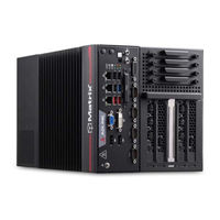
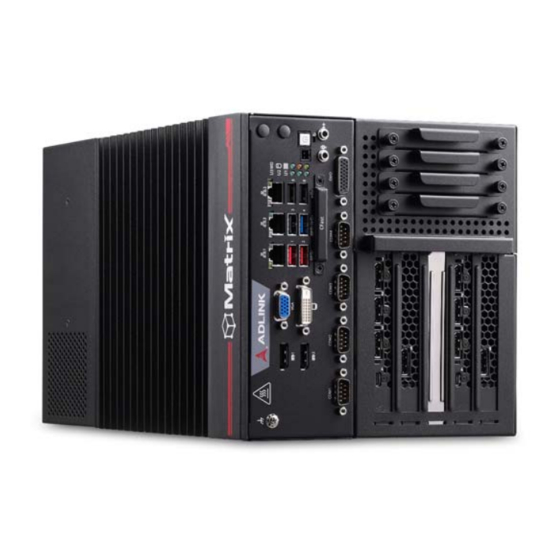
ADLINK Technology DLAP-8000 Series User Manual (103 pages)
High Performance 9th Generation Intel® Xeon®/Core™ i7/i5/i3 Processor Edge Workstation Computer
Brand:
ADLINK Technology
| Category:
Desktop
| Size: 9 MB
Table of Contents
Table of Contents
5
List of Tables
7
List of Figures
9
1 Introduction
11
Overview
11
Features
11
Packing List
12
2 Specifications
13
Dlap-800X/Dlap-8001/Dlap-8002/Dlap-8003
13
DLAP-8000 Functional Block Diagram
15
Display Options
16
Table 2-1: Max. Available Resolution Display Configurations
16
Mechanical Dimensions
17
Figure 2-1: DLAP-8000 Front View (Including Wall-Mount Brackets)
17
Figure 2-2: DLAP-8000 Left Side View
18
Figure 2-3: DLAP-8000 Right Side View
19
Figure 2-4: DLAP-8000 Top View
20
3 System Layout
21
Front Panel
21
Table 3-1: Front Panel I/O Legend
21
Figure 3-1: Front Panel I/O
21
Table 3-2: LED Indicators
22
Table 3-3: Displayport Pin Definition
23
Figure 3-2: Displayport Connector Pin Definition
23
Table 3-4: Applicable Cable Types
24
Figure 3-3: Digital I/O Connector Pin Definition
24
Table 3-5: Digital Input/Output Connector Pin Definition
25
Figure 3-4: Digital Input Circuit
25
Table 3-6: DVI-D Connector Pin Definition
26
Figure 3-5: Digital Output Circuit
26
Figure 3-6: DVI-D Connector Pin Definition
26
Table 3-7: VGA Connector Pin Definition
27
Figure 3-7: VGA Connector Pin Definition
27
Figure 3-8: Ethernet Port and Leds
28
Table 3-8: Ethernet Port Pin Definition
29
Table 3-9: Active/Link LED Indicators
29
Table 3-10: Speed LED Indicators
29
Table 3-11: DC Power Input Pin Definition
30
Table 3-12: Backplane DC Power Input Pin Definition
30
Figure 3-9: DC Power Input
30
Figure 3-10: Backplane DC Power Input
30
Table 3-13: D-Sub 9-Pin Signal Function of COM Ports
32
Figure 3-11: COM Port Pin Definition
32
Figure 3-12: Cfast Host Slot
33
Internal I/O Connectors
34
Figure 3-13: Mainboard Connectors
34
Table 3-14: Mainboard Connector Legend
35
Table 3-15: 5-Slot Backplane Board Connector Legend
36
Figure 3-14: 5-Slot Backplane Board Connectors
36
Table 3-16: GPS Module Power Header Pin Definition
37
Figure 3-15: GPS Module Power Header Pin Definition
37
Table 3-17: 12V Fan Connector Pin Definition
38
Figure 3-16: 12V Fan Connector Pin Definition
38
Figure 3-17: Clear CMOS Jumper Setting
38
Table 3-18: PWR/RESET Header Pin Definition
39
Table 3-19: 12V Power Pin Definition
39
Figure 3-18: PWR/RESET Header Pin Definition
39
Figure 3-19: 12V Power Pin Definition
39
4 Getting Started
41
Attach DC Power Connector
41
Mounting the DLAP-8000
42
Driver Installation
44
A Appendix: Power Consumption
45
Power Consumption Reference
45
Table A-1: Power Consumption
46
Table A-2: PEG Card Power Consumption
46
B Appendix: BIOS Setup
47
Main
48
Advanced
50
Chipset
67
Security
82
Boot
84
Save & Exit
86
C Appendix: Watchdog Timer (WDT)
89
Function Library
89
WDT with Api/Windows
89
WDT with Dos/Linux
92
D Appendix: Digital Input/Output
95
Function Library
95
Important Safety Instructions
97
Consignes de Sécurité Importante
99
Getting Service
103
Advertisement
Advertisement
Related Products
ADLINK Technology DLAP-401-Xavier
ADLINK Technology DLAP-211-JT2
ADLINK Technology DLAP-211-JT2S
ADLINK Technology DLAP-3000-CF Series
ADLINK Technology DLAP-3000-CFP35
ADLINK Technology DLAP3100-CFT1
ADLINK Technology DLAP3100-CFT3
ADLINK Technology DLAP3100-CFT5
ADLINK Technology DLAP-3100-CFP12
ADLINK Technology DLAP3200-CFP1
ADLINK Technology Categories
Computer Hardware
Motherboard
PCI Card
Control Unit
Desktop
More ADLINK Technology Manuals
Login
Sign In
OR
Sign in with Facebook
Sign in with Google
Upload manual
Upload from disk
Upload from URL