
Related Manuals for ADLINK Technology Value MVP-6200 Series


Summary of Contents for ADLINK Technology Value MVP-6200 Series
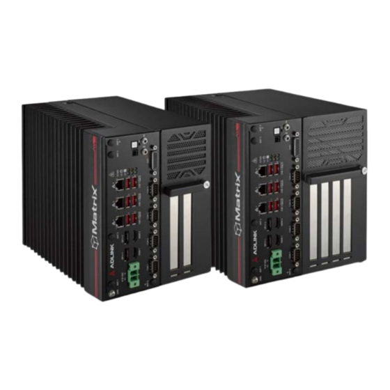
- Page 1 MVP-6200 Series Value Line 12th Gen Intel® Core™ i9/i7/i5/i3 Embedded Fanless Computer MVP-6220/MVP-6240 User’s Manual Manual Rev.: June 7, 2023 Revision Date: 50M-41053-1000 Part No:...
-
Page 2: Revision History
Revision History Revision Release Date Description of Change(s) 2023-06-07 Initial release Revision History... -
Page 3: Preface
MVP-6200 Series Preface Copyright © 2023 ADLINK Technology Inc. This document contains proprietary information protected by copy- right. All rights are reserved. No part of this manual may be repro- duced by any mechanical, electronic, or other means in any form without prior written permission of the manufacturer. - Page 4 California Proposition 65 Warning WARNING: This product can expose you to chemicals including acrylamide, arsenic, benzene, cadmium, Tris(1,3-dichloro-2-propyl) phosphate (TDCPP), 1,4- Dioxane, formaldehyde, lead, DEHP, styrene, DINP, BBP, PVC, and vinyl materials, which are known to the State of California to cause cancer, and acrylamide, benzene, cadmium, lead, mercury, phthalates, toluene, DEHP, DIDP, DnHP, DBP, BBP, PVC, and vinyl materials, which are known to the State of California to cause...
-
Page 5: Table Of Contents
MVP-6200 Series Table of Contents Revision History..............ii Preface ..................iii List of Tables................. vii List of Figures ................ ix 1 Introduction ................ 1 Overview................1 Features................2 Packing List ................. 2 Optional Accessories ............2 2 Specifications ..............3 MVP-6249, MVP-6247............ - Page 6 A Appendix: Power..............57 Power Consumption Reference ......... 57 B Appendix: BIOS Setup............59 Main ................... 60 Advanced ................62 Chipset................78 Security ................90 Boot ................... 92 Save & Exit ................ 94 MEBx ................. 96 C Appendix: Watchdog Timer (WDT) Function Library ..97 WDT with API/Windows .............
-
Page 7: List Of Tables
MVP-6200 Series List of Tables Table 2-1: Maximum Resolution Display Configurations ... 11 Table 3-1: Front/Side Panel I/O Legend ........18 Table 3-2: External Power Button Connector Pin Definition ..20 Table 3-3: DisplayPort Pin Definition ......... 21 Table 3-4: Digital Input/Output Connector Pin Definition ... - Page 8 This page intentionally left blank. viii List of Tables...
-
Page 9: List Of Figures
MVP-6200 Series List of Figures Figure 2-1: MVP-6200 Series Functional Block Diagram....11 Figure 2-2: MVP-6200 Series Top View........... 12 Figure 2-3: MVP-6200 Series 2 Slot Front View ......13 Figure 2-4: MVP-6200 Series 2 Slot Mounting......... 14 Figure 2-5: MVP-6200 Series 4 Slot Front View ......15 Figure 2-6: MVP-6200 Series 4 Slot Mounting......... - Page 10 This page intentionally left blank. List of Figures...
-
Page 11: Introduction
MVP-6200 Series Introduction 1.1 Overview ADLINK’s MVP-6200 Series of value line fanless embedded com- puting platforms, incorporating Intel® Core™ processors, provides one PCIe x16 and one PCI slot for a 2-slot backplane and one PCIe x16, two PCIe x4 and one PCI for a 4-slot backplane and also includes single-side access for I/O ports, optimizing easy maintenance in industrial automation environments. -
Page 12: Features
1.2 Features 12th Generation Intel® Core™ i9/i7/i5/i3 FCLGA1700 pro- cessor and R680E chipset 4x DDR5 SODIMM socket, supporting up to 128GB DDR5 3600 SODIMM module Expansion: MVP-6220 Series: 1x PCIe x16 + 1x PCI MVP-6240 Series: 1x PCIe x16 + 2x PCIe x4 + 1x PCI ... -
Page 13: Specifications
MVP-6200 Series Specifications 2.1 MVP-6249, MVP-6247 MVP-6249 MVP-6247 System Core Intel® Core™ i9-12900E Intel® Core™ i7-12700E Processor (16-cores, 65W, up to 5.00 GHz) (12-cores, 65W, up to 4.80 GHz) Chipset R680E Memory 4x SODIMM DDR5 3600 MHz, up to 128 GB I/O Interface Display 2x DP++, 2x HDMI (4 independent displays) - Page 14 MVP-6249 MVP-6247 Power Supply DC Input 9 to 32V AC Input 280W AC adapter (P/N: 31-62162-1010-A0) Environmental Standard Operating 0°C to 50°C, w/ airflow 0.6 m/s Temperature Extended -20°C to 50°C, w/ airflow 0.6 m/s Operating (w/ industrial storage) Temperature Storage -40°C to 85°C (excluding storage devices) Temperature...
-
Page 15: Mvp-6247T, Mvp-6245T
MVP-6200 Series 2.2 MVP-6247T, MVP-6245T MVP-6247T MVP-6245T System Core Intel® Core™ i7-12700TE Intel® Core™ i5-12500TE Processor (12-cores, 35W, up to 4.60 GHz) (6-cores, 35W, up to 4.30 GHz) Chipset R680E Memory 4x SODIMM DDR5 3600 MHz, up to 128 GB I/O Interface Display 2xDP++, 2xHDMI (4 independent displays) - Page 16 MVP-6247T MVP-6245T Power Supply DC Input 9 to 32V AC Input 280W AC adapter (P/N: 31-62162-1010-A0) Environmental Standard Operating 0°C to 60°C, w/ airflow 0.6 m/s Temperature Extended -20°C to 60°C, w/ airflow 0.6 m/s Operating (w/ industrial storage) Temperature Storage -40°C to 85°C (excluding storage devices) Temperature...
-
Page 17: Mvp-6229, Mvp-6227
MVP-6200 Series 2.3 MVP-6229, MVP-6227 MVP-6229 MVP-6227 System Core Intel® Core™ i9-12900E Intel® Core™ i7-12700E Processor (16-cores, 65W, up to 5.00 GHz) (12-cores, 65W, up to 4.80 GHz) Chipset R680E Memory 4x SODIMM DDR5 3600 MHz, up to 128 GB I/O Interface Display 2x DP++, 2x HDMI (4 independent displays) - Page 18 MVP-6229 MVP-6227 Power Supply DC Input 9 to 32V AC Input 280W AC adapter (P/N: 31-62162-1010-A0) Environmental Standard Operating 0°C to 50°C, w/ airflow 0.6 m/s Temperature Extended -20°C to 50°C, w/ airflow 0.6 m/s Operating (w/ industrial storage) Temperature Storage -40°C to 85°C (excluding storage devices) Temperature...
-
Page 19: Mvp-6227T, Mvp-6225T
MVP-6200 Series 2.4 MVP-6227T, MVP-6225T MVP-6227T MVP-6225T System Core Intel® Core™ i7-12700TE Intel® Core™ i5-12500TE Processor (12-cores, 35W, up to 4.60 GHz) (6-cores, 35W, up to 4.30 GHz) Chipset R680E Memory 4x SODIMM DDR5 3600 MHz, up to 128 GB I/O Interface Display 2xDP++, 2xHDMI (4 independent displays) - Page 20 MVP-6227T MVP-6225T Power Supply DC Input 9 to 32V AC Input 280W AC adapter (P/N: 31-62162-1010-A0) Environmental Standard Operating 0°C to 60°C, w/ airflow 0.6 m/s Temperature Extended -20°C to 60°C, w/ airflow 0.6 m/s Operating (w/ industrial storage) Temperature Storage -40°C to 85°C (excluding storage devices) Temperature...
-
Page 21: Mvp-6200 Series Functional Block Diagram
MVP-6200 Series 2.5 MVP-6200 Series Functional Block Diagram DDI-B(RVP) HDMI1.4 HDMI LS HDMI 1 CN CH0, 1 DDR5 SO-DIMM 1~4 PTN3360 Processor 2 DIMM - 3600 DDI-D(RVP) HDMI1.4 HDMI LS HDMI 2 CN Alder Lake S DDI-C(RVP) PTN3360 DP1 CN 35W/65W PCIe x16(GEN5) DDI-E(RVP) -
Page 22: Mechanical
2.7 Mechanical All dimensions in millimeters. 5.20 Detail A Figure 2-2: MVP-6200 Series Top View... -
Page 23: Figure 2-3: Mvp-6200 Series 2 Slot Front View
MVP-6200 Series Figure 2-3: MVP-6200 Series 2 Slot Front View... -
Page 24: Figure 2-4: Mvp-6200 Series 2 Slot Mounting
Rear Panel Mounting Bracket Orientation Bottom Panel Mounting Bracket Orientation Figure 2-4: MVP-6200 Series 2 Slot Mounting... -
Page 25: Figure 2-5: Mvp-6200 Series 4 Slot Front View
MVP-6200 Series Figure 2-5: MVP-6200 Series 4 Slot Front View... -
Page 26: Figure 2-6: Mvp-6200 Series 4 Slot Mounting
Rear Panel Mounting Bracket Orientation Bottom Panel Mounting Bracket Orientation Figure 2-6: MVP-6200 Series 4 Slot Mounting... -
Page 27: System Layout
MVP-6200 Series System Layout 3.1 Front/Side Panel I/O The MVP-6200 Series provides the following front and side panel access features. H B I Figure 3-1: Front Panel I/O Figure 3-2: Side Panel I/O... -
Page 28: Table 3-1: Front/Side Panel I/O Legend
Ground Reset Button Antenna x6 J COM Port x4 DC Power Input K USB 3.2 Gen 1 Type-A x2 DisplayPort++ x2 L Digital Input/Output Gigabit Ethernet x3 M Audio (Line-in, Line-out) LED Indicators N HDMI x2 External Power Button O USB 3.2 Gen 2 Type-A x4 Power Button Table 3-1: Front/Side Panel I/O Legend 3.1.1... - Page 29 MVP-6200 Series 3.1.3 LED Indicators In addition to the power button LED, six LEDs on the front panel indicate the following. LED Indicator Location Color Description Indicates watchdog timer status. When watchdog timer starts, the LED will be on until system boot Watchdog (WD) Top Right Yellow...
-
Page 30: Table 3-2: External Power Button Connector Pin Definition
3.1.6 PCI Express x4 Slot Two PCI Express x4 slots for the MVP-6240 Series supports expansion with standard PCIe Gen3 cards and full PCI express x4 signals. 3.1.7 Reset Button The reset button executes a hard reset for the MVP-6200 Series. 3.1.8 External Power Button Connector The MVP-6200 Series provides an external power button connec-... -
Page 31: Displayport Connectors
MVP-6200 Series 3.1.10 DisplayPort Connectors Two DisplayPort connectors on the front panel can connect to VGA, DVI, HDMI and DisplayPort monitors via DisplayPort to VGA adapter cable, DisplayPort to DVI adapter cable, or DisplayPort to HDMI adapter cable and DisplayPort cable. Figure 3-4: DisplayPort Connector Pin Definition Signal Signal... -
Page 32: Table 3-4: Digital Input/Output Connector Pin Definition
3.1.11 Digital I/O Connector The MVP-6200 Series provides 8 channels of non-isolation digital input and 8 channels of non-isolation digital output circuits, with spec and circuits as follows. 8-channel Digital Input VIH: 2 to 5.25V VIL: 0 to 0.8V ... -
Page 33: Figure 3-6: Digital Input Circuit
MVP-6200 Series Figure 3-6: Digital Input Circuit Figure 3-7: Digital Output Circuit... -
Page 34: Table 3-5: Hdmi Connector Pin Definition
3.1.12 HDMI Connector The MVP-6200 Series provides one HDMI connector for connec- tion to an external monitor. Pin # Signal Pin # Signal CON_HDMI_TX2_P CON_HDMI_TX2_N CON_HDMI_TX1_P CON_HDMI_TX1_N CON_HDMI_TX0_P CON_HDMI_TX0_N CON_HDMI_CLK_P CON_HDMI_CLK_N DVI_SCL_SINK DVI_SDA_SINK P_+5V0_HDMI_CN CON_HDMI_HPD_5V0 Table 3-5: HDMI Connector Pin Definition 3.1.13 USB 2.0 Ports The MVP-6200 Series provides one USB 2.0 Type-A port. -
Page 35: Table 3-6: Ethernet Port Pin Definition
MVP-6200 Series 3.1.15 Gigabit Ethernet Ports Three Gigabit Ethernet ports on the front panel support Intel I225- LM supports 2.5Gps. Speed LED Active/Link Green/Orange Yellow Figure 3-8: Ethernet Port and LEDs Pin # 10BASE-T/100BASE-TX 1000BASE-T LAN_TX0+ LAN_TX0- LAN_TX1+ — LAN_TX2+ —... -
Page 36: Table 3-9: Dc Power Input Pin Definition
3.1.16 DC Power Input 9-32 VDC Figure 3-9: DC Power Input Signal V+ (DC_IN) V- (DGND) Table 3-9: DC Power Input Pin Definition Refer to Section 4.2: Attach DC Power Connector on page 39 to install the DC Power Connector to the DC Power Input. Use an approved power source as certified by IEC or UL. -
Page 37: Com Port Connectors
MVP-6200 Series 3.1.17 COM Port Connectors The MVP-6200 Series provides four COM ports through D-sub 9- pin connectors. The COM1 & COM2 ports support RS-232/422/ 485 modes by BIOS setting, while COM3 and COM4 support only RS-232. Figure 3-10: COM Port Pin Definition Signal Name RS-232 RS-422... -
Page 38: Internal I/O Connectors
3.2 Internal I/O Connectors 3.2.1 Mainboard Top/Bottom Connector Locations Figure 3-11: Mainboard Top Connectors... -
Page 39: Table 3-11: Mainboard Top Connector Legend
MVP-6200 Series Power FW Update Connector (Debug) M.2 M Key CPU Socket DDR5 SO-DIMM1 DDR5 SO-DIMM3 Flash ROM Socket (Debug) DCIN Connector HDMI + DP HDMI + DP RJ45 + USB 3.0 x2 RJ45 + USB 3.0 x2 RJ45 + USB 3.0 x2 Extenal Power Connector Table 3-11: Mainboard Top Connector Legend... -
Page 40: Figure 3-12: Mainboard Bottom Connectors
Figure 3-12: Mainboard Bottom Connectors... -
Page 41: Table 3-12: Mainboard Bottom Connector Legend
MVP-6200 Series SATA connector for 2.5” SSD USB 2.0 dongle SATA connector for 2.5” SSD PCIE GEN5 slot for BP Board M.2 E Key System Fan Connector DDR5 SO-DIMM2 DDR5 SO-DIMM4 PCIE GEN4 + Power slot for BP Board External Power Connector for AFM Board I2C Wafer 2 (I2C1) I2C Wafer 1 (I2C0) SIM connector for M.2... -
Page 42: Table 3-13: 2-Slot Backplane Card Legend
3.2.2.1 2-slot Backplane Card Figure 3-13: 2-slot Backplane Card USB 2.0 dongle connector SATA power connector SATA signal connector (CN6 no function) PCI slot PCl express x16 slot Additional power for PCle x 16 slot (12V) Direct SATA connector Table 3-13: 2-slot Backplane Card Legend... -
Page 43: Table 3-14: 4-Slot Backplane Card Legend
MVP-6200 Series 3.2.2.2 4-slot Backplane Card Figure 3-14: 4-slot Backplane Card USB Type-A connector FAN connector SATA power connector SATA data connector (CN1 no function) SATA connector PCI connector PCIE x4 connector PCIE x16 connector Table 3-14: 4-slot Backplane Card Legend... -
Page 44: Table 3-15: Sata Connector Pin Definition
3.2.3 SATA Connector The SATA connector supports transfer up to 6.0Gb/s (600MB/s). Figure 3-15: SATA Connector Signal Table 3-15: SATA Connector Pin Definition 3.2.4 USB 2.0 Connector One USB 2.0 Type-A connector is provided on the mainboard for internal USB dongle, with another on the backplane board. Figure 3-16: USB Port Signal Data-... -
Page 45: Table 3-17: 12V Fan Connector Pin Definition
MVP-6200 Series 3.2.5 12V Fan Connector DC 12V fan module power supply is provided through the connec- tor, to which the optional fan module connects when installed in the chassis. Figure 3-17: 12V Fan Connector Pin Definition Signal FAN_GND 12V IN PWR FAN TACH FAN PWM Table 3-17: 12V Fan Connector Pin Definition... -
Page 46: Table 3-19: I2C Connector Pin Definition
3.2.7 I2C Connector There are two I2C connectors supporting 3.3v or 5v. Figure 3-19: I2C Connector Pin Definition Pin Signal (I2C0) Signal (I2C1) P_+5V0_S P_+5V0_S P_+3V3_S P_+3V3_S PCH_I2C0_SDA_S PCH_I2C1_SDA_S PCH_I2C0_SCL_S PCH_I2C1_SCL_S I2C0_GPIO I2C1_GPIO Table 3-19: I2C Connector Pin Definition 3.2.8 Micro-SIM Slot The Micro-SIM slot supports an M.2 B Key. -
Page 47: Table 3-20: Micro-Sim Slot Pin Definition
MVP-6200 Series Signal SIM PWR REST# DATA Table 3-20: Micro-SIM Slot Pin Definition 3.2.9 12V Power for Additional AFM MXM Carrier Board One 12V power pin header provides additional AFM MXM carrier board power for an MXM card, if used. Figure 3-21: 12V Power Pin Definition Signal Signal... - Page 48 This page intentionally left blank.
-
Page 49: Getting Started
MVP-6200 Series Getting Started 4.1 Package Contents Before unpacking, check the shipping carton for any damage. If the shipping carton and/or contents are damaged, inform your dealer immediately. Retain the shipping carton and packing mate- rials for inspection. Obtain authorization from your dealer before returning any product to ADLINK. -
Page 50: Installing Components
4.3 Installing Components 4.3.1 Install a Solid-State Drive (SSD) (Option 1) Follow these steps to install a solid-state drive (SSD). This option supports the installation of SSDs with a thickness of 9.5mm only. NOTE: NOTE: 1. Remove the top cover after loosening the thumbscrew. - Page 51 MVP-6200 Series 2. Using a screwdriver, remove the 4 rear panel case screws. 3. Remove the SSD tray.
- Page 52 4. Use the set of 8 included M3 screws to attach two 2.5" x 9.5mm SSD drives to the tray.
- Page 53 MVP-6200 Series 5. Gently insert the drives into the SATA connectors on the board. 6. Replace the top cover and return the thumbscrew. 4.3.2 Install a Solid-State Drive (SSD) (Option 2) Follow these steps to install a solid-state drive (SSD). This option supports the installation of SSDs with a thickness up to 15mm.
- Page 54 1. Prepare the SSD assembly using the following parts. 1x Bracket 8x Screws 1x Short SATA Data/Power Cable 1x Long SATA Data/Power Cable Attach up to 2 SSDs to the bracket with the supplied screws, and then attach the short and long SATA data/ power cables.
- Page 55 MVP-6200 Series 2. Remove the top cover after loosening the thumbscrew. 3. Using a screwdriver, remove the 4 side panel case screws.
- Page 56 4. Put the SSD assembly into the system and attach it to the case with the 4 side panel case screws. 5. Connect the SSD data/power cables to the board as shown. 6. Replace the top cover and return the thumbscrew.
- Page 57 MVP-6200 Series 4.3.3 Install SODIMM Memory Follow these steps to install SODIMM memory. 1. Remove the top cover after loosening the thumbscrew. 2. Attach the included thermal pads to the main board under the location of the SODIMM modules. Make sure the thermal pads DO NOT contact the connector pins.
- Page 58 4.3.4 Install Wi-Fi Module Follow these steps to install a Wi-Fi module. 1. Remove the top cover after loosening the thumbscrew. 2. Install the Wi-Fi module and lock in place with the included M3 screw. 3. Replace the top cover and return the thumbscrew.
- Page 59 MVP-6200 Series 4.3.5 Install 5G Module Follow these steps to install a 5G module. 1. Remove the top cover after loosening the thumbscrew. 2. Attach the included M2.5 standoff screw to one of two locations on the main board, depending on the size of the module.
- Page 60 3. Install the 5G module and secure it with the included M2 screw. 4. Replace the top cover and return the thumbscrew. 4.3.6 Install Fan Kit Follow these steps to install a fan kit. 1. Remove the top cover after loosening the thumbscrew.
- Page 61 MVP-6200 Series 2. Connect the fan connector to the board first, and then fasten the fan assembly kit to the chassis. 3. Replace the top cover and return the thumbscrew.
-
Page 62: Mounting The Mvp-6200 Series
4.4 Mounting the MVP-6200 Series 4.4.1 Install the Wall-mount Brackets (Rear Panel) Follow these steps to install the wall-mount brackets on the rear panel. 1. Use the 6 M4 screws shipped with the controller to attach the 2 included wall mount brackets to the chassis as shown. - Page 63 MVP-6200 Series 4.4.2 Install the Wall-mount Brackets (Side Panel) Follow these steps to install the wall-mount brackets on the side panel. 1. Use the 6 M4 screws shipped with the controller to attach the 2 included wall mount brackets to the chassis as shown.
-
Page 64: Pcie/Pci Board Clearance
4.5 PCIe/PCI Board Clearance The following diagrams show the PCIe/PCI board clearances when using the respective SSD types. -
Page 65: Driver Installation
MVP-6200 Series 4.6 Driver Installation Download the drivers for your system from the product page at https://www.adlinktech.com/Products/Industrial_PCs_Fanless_ Embedded_PCs/IntegratedFanlessEmbeddedComputers/MVP- 6200 Series_Series. - Page 66 This page intentionally left blank.
-
Page 67: Appendix A Power
MVP-6200 Series Appendix A Power Information in this Appendix is for power budget planning and design purposes only. Actual power consumption may differ based on final application. NOTE: NOTE: A.1 Power Consumption Reference Power consumption as follows is based on lab data in which 24V DC is applied and current is measured by the DC power supply. - Page 68 This page intentionally left blank.
-
Page 69: Appendix B Bios Setup
MVP-6200 Series Appendix B BIOS Setup The Basic Input/Output System (BIOS) is a program that provides a basic level of communication between the processor and peripherals. In addition, the BIOS also contains codes for various advanced features applied to the MVP-6200. The BIOS Setup program includes menus for configuring settings and enabling features of the MVP-6200. -
Page 70: Main
B.1 Main Contains basic system information for the MVP-6200. Changing BIOS settings may lead to incorrect controller behav- ior and possible inability to boot. WARNING: BIOS Information Shows current system BIOS Vendor, BIOS Version, Build Date, MRC Version, GOP Version and ME FW Version. System Information Shows current system Project Name, CPU Board Version, CPU Branding String, CPU Stepping, GT Info, CPU Frequency, Total... - Page 71 MVP-6200 Series System Time/System Date Allows adjustment of system time and date, as follows. 1. Highlight System Time or System Date using the up and down <Arrow> keys. 2. Enter new values using the keyboard and select <Enter>. 3. Select < Tab > to move between fields. The date must be entered in MM/DD/YY format, and the time in HH:MM:SS.
-
Page 72: Advanced
B.2 Advanced Setting incorrect or conflicting values in Advanced BIOS Setup may cause system malfunction. CAUTION: Accesses advanced options of the MVP-6200. - Page 73 MVP-6200 Series B.2.1 CPU Configuration Hyper-Threading Enabled for Windows and Linux (optimized for Hyper-Threading Technology) and Disabled for other OS (not optimized for Hyper- Threading Technology). When Disabled only one thread per enabled core is enabled. Active Performance-cores Number of P-cores to enable in each processor package. Note: Number of Cores and E-cores are looked at together.
- Page 74 Intel (VMX) Virtualization Technology When enabled, a VMM can utilize the additional hardware capabil- ities provided by Vanderpool Technology. Intel Trusted Execution Technology Enables utilization of additional hardware capabilities provided by Intel(R) Trusted Execution Technology. Changes require a full power cycle to take effect. ®...
- Page 75 MVP-6200 Series B.2.2 Power Management State After G3 Specifies the state to go to when power is re-applied after a power failure (G3 state). RTC Wake system from S5 Enable or disable System wake on alarm event. Select FixedTime for the system to wake at the hr::min::sec specified. Select DynamicTime for the system to wake at the current time + Increase minute(s).
- Page 76 B.2.3 Serial Console Redirection COM1 Console Redirection Enables/disables SIO COM1 Console Redirection. Console Redirection Settings Specify how the host computer and the remote computer (in use) exchange data. Both computers should have the same or compat- ible settings.
- Page 77 MVP-6200 Series B.2.4 USB Configuration USB Mass Storage Driver Support Enables/disables USB mass storage driver support. USB transfer time-out The time-out value for Control, Bulk, and Interrupt transfers. Device reset time-out USB mass storage device Start Unit command time-out. Device power-up delay Maximum time the device will take before it properly reports itself to the Host Controller, where Auto uses default value for Root port 100ms, and for Hub port the delay is taken from Hub descriptor.
- Page 78 B.2.5 TPM 2.0 Configuration Security Device Support Enables/disables BIOS support for security device. OS will not show Security Device. TCG EFI protocol and INT1A interface will not be available. SHA256 PCR Bank Enables/disables SHA256 PCR Bank. Pending Operation Schedules Operation for the Security Device. Computer will reboot during restart in order to change State of Security Device.
- Page 79 MVP-6200 Series Storage Hierarchy Enables/disables Storage Hierarchy. Endorsement Hierarchy Enables/disables Endorsement Hierarchy. Physical Presence Spec Version Directs OS to support PPI Spec Version 1.2 or 1.3. Some HCK tests may not support 1.3. TPM 2.0 Interface Type Select the Communication Interface to TPM 20 Device. PH Randomization Enables or Disables Platform Hierarchy randomization.
- Page 80 B.2.6 Onboard Devices Configuration COM1 Mode Control Selects COM1 mode from RS232, RS422 or RS485. COM2 Mode Control Selects COM2 mode from RS232, RS422 or RS485. LAN #1 (Intel I225) Enables/disables I225 LAN1. LAN #2 (Intel I225) Enables/disables I225 LAN2. LAN #3 (Intel I225) Enables/disables I225 LAN3.
- Page 81 MVP-6200 Series B.2.7 NCT6126D HW Monitor Displays CPU/Board Temperatures, System/Backplane speeds, and various Voltages.
- Page 82 System Fan Control Mode Configures fan control mode from Manual Mode, Auto Mode, and SMART FAN IV. Manual Mode Allows configuration of a set fan duty cycle.
- Page 83 MVP-6200 Series Auto Mode Fan runs at automatic speed for optimal thermal solution.
- Page 84 SMART FAN IV Four temperatures and four fan duties can be user-configured.
- Page 85 MVP-6200 Series B.2.8 BIOS Watchdog Timer BIOS POST Watchdog Disable disables WatchDog Timer, Second Mode enables Watch- dog Timer in second mode, Minute Mode enables Watchdog Timer in minute mode.
- Page 86 B.2.9 Network Stack Configuration Network Stack Enables/disables UEFI Network Stack.
- Page 87 MVP-6200 Series B.2.10 Intel® Ethernet Controller (3) I225-IT Displays UEFI Driver, Device Name, Link Status and MAC Address.
-
Page 88: Chipset
B.3 Chipset Setting incorrect or conflicting values in Chipset BIOS Setup may cause system malfunction WARNING:... - Page 89 MVP-6200 Series B.3.1 System Agent (SA) Configuration System Agent (SA) Configuration Displays and configures VT-d capability and provides settings for Memory, Graphics, and DMI/OPI configuration.
- Page 90 B.3.1.1 Memory Configuration Memory Configuration Displays memory speed, size, maker, and configuration.
- Page 91 MVP-6200 Series B.3.1.2 Graphics Configuration Primary Display Select which of IGFX/PEG/PCI Graphics device should be the Pri- mary Display. Internal Graphics Keeps IGFX enabled based on Setup options. GTT Size Selects GTT Size. Aperture Size Selects Aperture Size. DVMT Pre-Allocated Selects DVMT 5.0 Pre-Allocated (Fixed) Graphics Memory size used by the Internal Graphics Device.
- Page 92 B.3.1.3 DMI/OPI Configuration DMI/OPI Configuration Displays DMI link speed and width. DMI Max Link Speed Sets DMI Speed to Gen1/Gen2/Gen3/Gen4.
- Page 93 MVP-6200 Series B.3.2 PCH-IO Configuration PCH-IO Configuration Configures SATA, NVMe, VMD, and Secruity.
- Page 94 B.3.2.1 SATA Configuration SATA Mode Selection Determines how SATA controller(s) operate. SATA Controller Speed Sets maximum speed the SATA controller can support. SATA HDD 0 Enables/disables SATA HDD 0. SATA HDD 1 Enables/disables SATA HDD 1. SATA HDD 2 Enables/disables SATA HDD 2.
- Page 95 MVP-6200 Series M.2 SATA Enables/disables M.2 SATA. B.3.2.2 NVMe Configuration Displays NVMe device status.
- Page 96 B.3.2.3 VMD Setup Menu Enable VMD controller Enable/Disable VMD controller. Enable VMD Global Mapping Enable/Disable VMD Global Mapping. RAID0 Enable/Disable RAID0 support. RAID1 Enable/Disable RAID1 support. RAID5 Enable/Disable RAID5 support.
- Page 97 MVP-6200 Series RAID10 Enable/Disable RAID10 support. Intel Rapid Recovery Technology Enable/Disable Intel Rapid Recovery Technology. RRT volumes can span internal and eSATA drives Enable/Disable RRT volumes can span internal and eSATA drives. Intel® Optane™ Memory Enable/Disable System Acceleration with Intel® Optane™ Mem- ory feature.
- Page 98 B.3.2.4 Security Configuration BIOS Lock Enables/disables PCH BIOS Lock Enable. Required to be enabled to ensure SMM flash protection.
- Page 99 MVP-6200 Series B.3.3 BackPlane PCIe Configuration Displays BackPlane model name, slot information, speed control, and time tunings. B.3.4 PCH digital I/O device Disable/Enable ACPI GPIO Device support for PCH digital I/O and user LED.
-
Page 100: Security
B.4 Security If only the Administrator password is set, access is limited and the password requested on Setup. If User password is set, it acts as a power-on password and must be entered to boot or enter setup. Administrator Password Sets Administrator Password. - Page 101 MVP-6200 Series B.4.1 Secure Boot Menu Secure Boot Control Active if Secure Boot is Enabled, Platform Key (PK) is enrolled and the System is in User mode. Mode change requires platform reset. Secure Boot Mode Selects from Standard or Custom. In Custom, Secure Boot Policy variables can be configured by a physically present user without full authentication.
-
Page 102: Boot
B.5 Boot Setup Prompt Timeout Number of seconds to wait for setup activation key. The maximum value is 8. Bootup Num-Lock State Sets keypad Number Lock status following boot. Quiet Boot Option Description Disabled Directs BIOS to display POST messages Enabled Directs BIOS to display the OEM logo. - Page 103 MVP-6200 Series Fast Boot Option Description Disabled Directs BIOS to perform all POST tests. Directs BIOS to skip certain POST tests to boot Enabled faster. While enabling Fast Boot can reduce system ready time, some prerequisites can reduce effectiveness. Boot Configuration Specifies the priority of boot devices, all of which are detected dur- ing POST and displayed.
-
Page 104: Save & Exit
B.6 Save & Exit Save Changes and Exit Exits system setup after saving the changes. Discard Changes and Exit Exits system setup without saving any changes. Save Changes and Reset Resets the system setup after saving changes. Discard Changes and Reset Resets system setup without saving any changes. - Page 105 MVP-6200 Series Save Changes Saves Changes so far to any of the setup options. Discard Changes Discards Changes so far to any of the setup options. Restore Defaults Sets all BIOS options to default settings, designed for maximum system stability but less than maximum performance. Select Restore Defaults if the computer encounters system configuration problems.
-
Page 106: Mebx
B.7 MEBx Intel® AMT Enable/Disable Intel® AMT support. Intel® AMT Configuration Select Intel® AMT configurations in BIOS. -
Page 107: Appendix C Watchdog Timer (Wdt) Func- Tion Library
MVP-6200 Series Appendix C Watchdog Timer (WDT) Func- tion Library This appendix describes use of the watchdog timer (WDT) func- tion library for the MVP-6200 controller. The watchdog timer is a hardware mechanism provided to reset the system if the operating system or an application stalls. - Page 108 SetWDT Sets the timeout value of the watchdog timer. There are two parameters for this function to indicate the timeout ticks and unit. ResetWDT or StopWDT should be called before the expi- ration of watchdog timer, or the system will reset. Syntax C/C++ BOOL SetWDT(BYTE tick, BYTE unit)
- Page 109 MVP-6200 Series Parameters None Return codes TRUE if watchdog timer is successfully started. FALSE if watchdog timer is failed to start. ResetWDT Reset the watchdog timer. The invocation of ResetWDT allows restoration of the watchdog timer to the initial timeout value specified in SetWDT function.
-
Page 110: Wdt With Dos/Linux
C.2 WDT with DOS/Linux Under Linux, please program the WDT function using the eSPI IO registers according to the sample program as follows. #include <dos.h> #include <stddef.h> #include <stdio.h> /* Config NCT6126D to enter config mode */ EnterConfig(void) outp(0x4E, 0x87); outp(0x4E, 0x87);... - Page 111 MVP-6200 Series printf("Init and config GPIO ports<<<<<<<<<<<<<<<<<<<<<<<<<\n"); printf("---------------------------------------------- ----\n"); EnterConfig(); /* config WDT registers */ w_reg(0x07,0x08); /* enable keyboard interrupt to reset WDT timeout value */ w_reg(0xF2,r_reg(0xF2)|0x40); /* set unit as second */ w_reg(0xF0,r_reg(0xF0)&~0x04); /* start the Watchdog */ w_reg(0x30,0x01); /* set timeout value as 30 seconds */ /* WDT start automatically while timeout value is set w_reg(0xF1,0x1E);...
- Page 112 printf("WDT is disable. Program is terminating."); ExitConfig(); return 0;...
-
Page 113: Appendix D Digital Input/Output Function Library
MVP-6200 Series Appendix D Digital Input/Output Function Library DI/O provides input/output to support inter-device communica- tions. Simple programming guides allow easy transmission of digi- tal signals between the system and attached peripherals. DI/O with API/Windows Matrix DI/O API library files and a demo program (incl. source code) can be downloaded from http://www.adlinktech.com. - Page 114 Parameter(s) Index Indexes the digital logic state of MVP-6200 digital input chan- nels 1 to 8 (bit 0 to 7) Value Sets the digital logic state of MVP-6200 digital output channels 1 to 8 (bit 0 to 7) to 0 or 1. Return codes 0: Operation Success -1: Operation Failed...
-
Page 115: Important Safety Instructions
MVP-6200 Series Important Safety Instructions For user safety, please read and follow all instructions, Warnings, Cautions, and Notes marked in this manual and on the associated device before handling/operating the device, to avoid injury or damage. Read these safety instructions carefully. ... - Page 116 A Lithium-type battery may be provided for uninterrupted backup or emergency power. Risk of explosion if battery is replaced with one of an incorrect type; please dispose of used batteries appropriately. CAUTION: The device must be serviced by authorized technicians ...
-
Page 117: Consignes De Sécurité Importante
MVP-6200 Series Consignes de Sécurité Importante S'il vous plaît prêter attention stricte à tous les avertissements et mises en garde figurant sur l'appareil, pour éviter des blessures ou des dommages. Lisez attentivement ces consignes de sécurité. Conservez le manuel de l'utilisateur pour pouvoir le con- sulter ultérieurement. - Page 118 Fixez le cordon d'alimentation (ne placez aucun objet sur le cordon d'alimentation). Installez/fixez et utilisez l'appareil uniquement sur des surfaces stables et/ou sur les fixations recommandées. L'ordinateur Smart Touch est alimenté par un adapta- teur ou une source CC. Veuillez vous assurer que l'adaptateur ou la source CC doit conserver la connexion à...
- Page 119 MVP-6200 Series Réservé au personnel de service qualifié ou aux utilisa- teurs familiarisés avec les restrictions appliquées à l'emplacement, aux raisons de ces restrictions et toutes les précautions requises Uniquement autorisé par l'utilisation d'un outil, d'une serrure et d'une clé, ou d'un autre moyen de sécurité, et contrôlé...
- Page 120 This page intentionally left blank. Consignes de Sécurité Importante...
-
Page 121: Getting Service
6450 Via Del Oro, San Jose, CA 95119-1208, USA Tel: +1-408-360-0200 Toll Free: +1-800-966-5200 (USA only) Fax: +1-408-600-1189 Email: info@adlinktech.com ADLINK Technology (China) Co., Ltd. 300 Fang Chun Rd., Zhangjiang Hi-Tech Park Pudong New Area, Shanghai, 201203 China Tel: +86-21-5132-8988 Fax: +86-21-5132-3588 Email: market@adlinktech.com ADLINK Technology GmbH Hans-Thoma-Straße 11...
Need help?
Do you have a question about the Value MVP-6200 Series and is the answer not in the manual?
Questions and answers