
Subscribe to Our Youtube Channel
Related Manuals for ADLINK Technology SP-AL


Summary of Contents for ADLINK Technology SP-AL
- Page 1 SP-AL Open Frame Panel PC User’s Manual Manual Rev.: June 22, 2018 Revision Date: 50-1Z258-1000 Part No: Leading EDGE COMPUTING...
- Page 2 Leading EDGE COMPUTING Revision History Revision Release Date Description of Change(s) June 22, 2018 Initial Release...
- Page 3 SP-AL Preface Copyright 2018 ADLINK Technology Inc. This document contains proprietary information protected by copy- right. All rights are reserved. No part of this manual may be repro- duced by any mechanical, electronic, or other means in any form without prior written permission of the manufacturer.
- Page 4 Leading EDGE COMPUTING Battery Labels (for products with battery) California Proposition 65 Warning WARNING: This product can expose you to chemicals including acrylamide, arsenic, benzene, cadmium, Tris(1,3-dichloro-2-propyl) phosphate (TDCPP), 1,4- Dioxane, formaldehyde, lead, DEHP, styrene, DINP, BBP, PVC, and vinyl materials, which are known to the State of California to cause cancer, and acrylamide, benzene, cadmium, lead, mercury, phthalates, toluene, DEHP, DIDP, DnHP, DBP, BBP, PVC, and vinyl materials, which are known to the State of California to cause...
- Page 5 SP-AL Information to prevent minor physical injury, component dam- age, data loss, and/or program corruption when trying to com- plete a task. CAUTION: Information to prevent serious physical injury, component damage, data loss, and/or program corruption when trying to complete a specific task.
- Page 6 Leading EDGE COMPUTING This page intentionally left blank. Preface...
-
Page 7: Table Of Contents
SP-AL Table of Contents Preface ..................iii List of Tables................ xiii List of Figures ............... xv 1 Introduction ............... 1 Features................1 General Specifications............2 Display/Touch Specifications..........4 Power Consumption ............5 Thermal Specification ............6 1.5.1 Heat Sink Specifications..........6 1.5.2... - Page 8 Leading EDGE COMPUTING 1.8.6 I2C Connector............27 1.8.7 Data Input Keys ............28 1.8.8 Power & Reset Connector ........29 1.8.9 2W Speaker Connectors........... 30 1.8.10 MIC in\Line out Connectors ........31 1.8.11 M.2 SSD slot............. 31 1.8.12 LED Connector ............32 1.8.13 I2C Connector............
- Page 9 SP-AL Installing the SEMA Utility, WDT and DI/O Drivers.... 51 A Appendix: BIOS Setup ............53 Main ................... 54 BIOS Information ............54 System Information ............54 System Time/System Date ........... 55 Access Level ..............55 A.1.1 Board Information ............. 56 Runtime Statistics ............
- Page 10 Leading EDGE COMPUTING RTC Wake system from S5 .......... 64 Emulation AT/ATX ............64 LAN#1 Control .............. 64 LAN#2 Control .............. 64 Power Consumption ............. 64 A.2.4 System Management..........66 SEMA Features ............66 Flags ................66 A.2.5 Thermal Management..........67 Critical Trip Point ............
- Page 11 SP-AL A.3.4 South Cluster Configuration ........80 HD-Audio Configuration ..........80 LPSS Configuration ............80 PCI Express Configuration ........... 80 SATA Drives ..............81 SCC Configuration ............81 USB Configuration ............81 Miscellaneous Configuration ......... 83 Security................84 Administrator Password ..........84 User Password .............
- Page 12 Leading EDGE COMPUTING Important Safety Instructions..........91 Getting Service ..............95 Table of Contents...
-
Page 13: List Of Tables
SP-AL List of Tables Table 1-1: External I/O Legend..........17 Table 1-2: DB-9P COM Port Pin Assignment ......18 Table 1-3: USB Ports Pin Assignment........19 Table 1-4: DisplayPort Pin Assignment ........20 Table 1-5: Gigabit Ethernet Port LED Function ......21 Table 1-6: Internal I/O Legend........... - Page 14 Leading EDGE COMPUTING This page intentionally left blank. List of Tables...
-
Page 15: List Of Figures
SP-AL List of Figures Figure 1-1: 10.1” Panel Front View ..........7 Figure 1-2: 10.1” Panel (Left) Side View........8 Figure 1-3: 12.1” Panel Front View ..........9 Figure 1-4: 12.1” Panel (Left) Side View........10 Figure 1-5: 15.6” Panel Front View ..........11 Figure 1-6: 15.6”... - Page 16 Leading EDGE COMPUTING This page intentionally left blank. List of Figures...
-
Page 17: Introduction
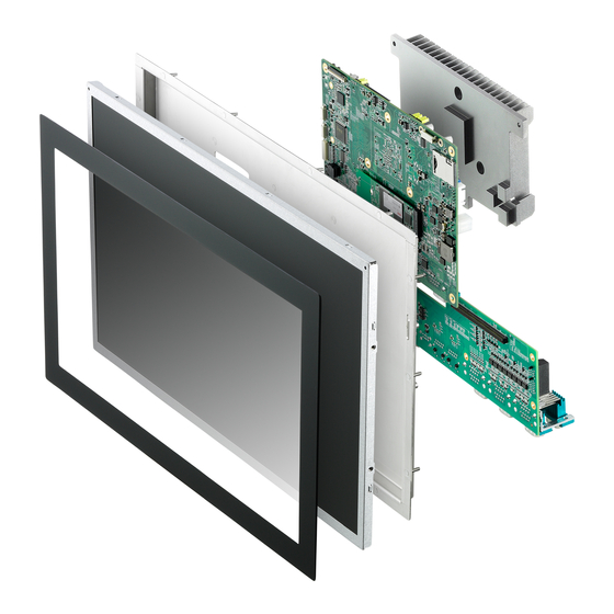
14nm technology, to be paired with the Apollo Lake Platform. is an embedded open frame panel computer meeting diverse form factors for vertical usage. The SP-AL provides a wide range of dis- play, touch, and I/O options to bring products to market quickly. -
Page 18: General Specifications
Leading EDGE COMPUTING 1.2 General Specifications Intel® Atom™ E3930 1.3/1.8GHz (Turbo), 6W (2C/1866) Processors Intel® Atom™ E3950 1.6/2.0GHz (Turbo), 12W (4C/1866) AMI EFI in 16MB SPI BIOS BIOS 1x SODIMM non-ECC 1867/1600 MHz DDR3L memory up Memory to 8 GB eMMC 5.0, up to 64GB (Optional) 1x SATA 6Gb/s, SATA power connector Storage... - Page 19 SP-AL Connector 1x 4-pin power connector DC Input 12VDC, optional 9-36VDC Power Power/Reset 1x wafer for power and reset button 2x thermal sensors located on top and Thermal bottom side (1 optional) TPM 2.0 (optional) 1x wafer for 10 LED indicators (4x COM port...
-
Page 20: Display/Touch Specifications
Leading EDGE COMPUTING 1.3 Display/Touch Specifications Resolution: 1024 x 600 Viewing angle: 75/75/70/75 Luminance: 250 nits (typ) 7” Operating temperature: -20°C to +60°C Storage temperature: -30°C to +80°C Resolution: 1280 x 800 Viewing angle: 85/85/85/85 Luminance: 400 nits (typ) 10.1" Operating temperature: -20°C to +60°C Storage temperature: -30°C to +70°C Resolution: 1280 x 800... -
Page 21: Power Consumption
SP-AL 1.4 Power Consumption Standard DC input is 12V, with optional 9 to 36V, both of which are supported by the flat panel. Component Specification Related Function Adapter: 12V, 10A, total 120W Adapter: 24V, 6.67A, 9 to 36V total 160W... -
Page 22: Thermal Specification
Leading EDGE COMPUTING 1.5 Thermal Specification 1.5.1 Heat Sink Specifications Heat sink designation is based on open frame locations such as kiosk installation. For Panel PC, design concept will differ. Dimensions CPU TDP Part Material (mm) E3930 72x67x6.01 CPU heat sink AL6063 E3950 79x102x48.2 1.5.2... -
Page 23: Mechanical Drawings
SP-AL 1.6 Mechanical Drawings All dimensions shown are in millimeters (mm) unless otherwise stated. NOTE: NOTE: 1.6.1 10.1” Panel 257.60 176.20 Figure 1-1: 10.1” Panel Front View Introduction... -
Page 24: Figure 1-2: 10.1" Panel (Left) Side View
Leading EDGE COMPUTING 51.2 Figure 1-2: 10.1” Panel (Left) Side View Introduction... -
Page 25: Panel
SP-AL 1.6.2 12.1” Panel 301.72 203.80 Figure 1-3: 12.1” Panel Front View Introduction... -
Page 26: Figure 1-4: 12.1" Panel (Left) Side View
Leading EDGE COMPUTING 53.5 Figure 1-4: 12.1” Panel (Left) Side View Introduction... -
Page 27: Panel
SP-AL 1.6.3 15.6” Panel 388.83 238.14 Figure 1-5: 15.6” Panel Front View Introduction... -
Page 28: Figure 1-6: 15.6" Panel (Left) Side View
Leading EDGE COMPUTING 53.29 Figure 1-6: 15.6” Panel (Left) Side View Introduction... -
Page 29: Panel
SP-AL 1.6.4 18.5” Panel 454.40 Figure 1-7: 18.5” Panel Front View Introduction... -
Page 30: Figure 1-8: 18.5" Panel (Left) Side View
Leading EDGE COMPUTING 57.30 Figure 1-8: 18.5” Panel (Left) Side View Introduction... -
Page 31: Panel
SP-AL 1.6.5 21.5” Panel 521.24 312.71 Figure 1-9: 21.5” Panel Front View Introduction... -
Page 32: Figure 1-10: 21.5" Panel (Left) Side View
Leading EDGE COMPUTING 57.50 Figure 1-10: 21.5” Panel (Left) Side View Introduction... -
Page 33: External I/O Connectors
SP-AL 1.7 External I/O Connectors The following lists I/O connectors located on the rear panel of the SP-AL. Figure 1-11: External I/O COM port x2 USB2.0 USB3.0 DisplayPort LAN x2 Table 1-1: External I/O Legend 1.7.1 DB-9P COM Port Connector Through a D-sub 9-pin connector, COM1 or COM2 supports RS- 232 (default) and RS-422/RS-485 modes, by BIOS setting. -
Page 34: Table 1-2: Db-9P Com Port Pin Assignment
Leading EDGE COMPUTING Figure 1-12: DB-9P COM Port Signal RS-232 RS-422 RS-485 DCD# TXD422- 485- TXD422+ 485+ RXD422+ DTR# RXD422- DSR# RTS# CTS# Table 1-2: DB-9P COM Port Pin Assignment Introduction... -
Page 35: Usb Ports
SP-AL 1.7.2 USB Ports Figure 1-13: USB Ports Connector Signal USB3.0_VBUS USB 3.0 SSRX- SSRX+ SSTX- SSTX+ USB2.0_VBUS USB 2.0 Table 1-3: USB Ports Pin Assignment 1.7.3 DisplayPort Connector One DisplayPort connector supports the DP++ standard specifica- tion, and can connect to VGA, DVI, HDMI, and Display Port moni-... -
Page 36: Table 1-4: Displayport Pin Assignment
Leading EDGE COMPUTING tors via DisplayPort to VGA adapter cable, DisplayPort to DVI adapter cable, or DisplayPort to HDMI adapter cable and Display Port cable, with DP1.2 support for resolutions up to 4096 x 2160 at 60Hz. Pin Signal Pin Signal ML_Lane0_P 11 GND 12 ML_Lane3_N... -
Page 37: Dual Gigabit Ethernet Ports
SP-AL 1.7.4 Dual Gigabit Ethernet Ports Two Gigabit Ethernet ports on the front panel support the Intel i211AT (MAC/PHY) GbE controller (i210IT for extreme tempera- ture operating support), which provides: IEEE 802.3az Energy Efficient Ethernet IEEE 1588/802.1AS precision time synchronization ... -
Page 38: Internal I/O Connectors
Leading EDGE COMPUTING 1.8 Internal I/O Connectors Figure 1-14: Internal I/O (Mainboard Top Side) Introduction... -
Page 39: Figure 1-15: Internal I/O (Mainboard Underside)
SP-AL Figure 1-15: Internal I/O (Mainboard Underside) Power connector SMBUS connector Mini PCIe port CMOS jumper USB 2.0 C connector Data input keys Power & reset 2W speaker (x2) Mic in/Line out M.2 SSD C connector Introduction... -
Page 40: Power Connector
Leading EDGE COMPUTING Control keys Debug GPI/O SIM card port Table 1-6: Internal I/O Legend 1.8.1 Power Connector The 4-pin power connector connects AC/DC power supply adapter, DC to DC power module and battery, with AT and ATX power modes (AT mode start is controlled by BMC). Figure 1-16: Power Connector Signal Table 1-7: Power Connector Pin Assignments... -
Page 41: Mini Pcie Port
PCIe gen2 and USB2.0. 1.8.4 CMOS Jumper Under conditions in which the SP-AL fails to boot, clearing the BIOS content stored in CMOS and restoring the default settings may be effective. To clear CMOS (located at JP1501), short Pin 2 and Pin 3 and wait for 5 seconds. -
Page 42: Usb 2.0 Port
Leading EDGE COMPUTING Figure 1-18: CMOS Jumper Signal P_+VCC_RTC_CN_A SOC_RTC_RST-L Table 1-9: CMOS Jumper Pin Assignments 1.8.5 USB 2.0 Port Supports connection to USB devices by cable. Figure 1-19: USB 2.0 Port Introduction... -
Page 43: I2C Connector
SP-AL Signal P5V_U2_USB_3 CN_USB2_P3N CN_USB2_P3P Table 1-10: USB 2.0 Port Pin Assignments 1.8.6 C Connector The top-mounted I2C connector supports I2C clients such as IOT sensors, connected by cable. Figure 1-20: I C Connector Signal P_+5V_A P_+3V3_A Table 1-11: I... -
Page 44: Data Input Keys
Leading EDGE COMPUTING Signal I2C_DAT_IOT I2C_CLK_IOT I2C_INT_IOT Table 1-11: I C Connector Pin Assignments 1.8.7 Data Input Keys One connector supports 32 physical keys and 5 control keys, with default values of: Direction: ↑, ↓, ←, → Number: 0 to 9 Function: Enter, ESC, TAB, Backspace, Delete, Clear, PagUp, PagDn Hot keys: F1 - F10... -
Page 45: Power & Reset Connector
SP-AL Function Function Signal Signal Value Code Value Code P_+3V3_S0 EC_BTN_17 ˄ EC_BTN_1 EC_BTN_18 ˅ EC_BTN_2 Backspace EC_BTN_19 ˃ EC_BTN_3 Delete EC_BTN_20 ˂ EC_BTN_4 Space 0x39 EC_BTN_21 EC_BTN_5 Page up Page EC_BTN_22 EC_BTN_6 down EC_BTN_23 EC_BTN_7 EC_BTN_24 EC_BTN_8 EC_BTN_25 EC_BTN_9... -
Page 46: Speaker Connectors
Leading EDGE COMPUTING Figure 1-22: Power & Reset Connector Signal P_+3V3_BMC_A PWRBTN-L_R SYS_RESET-L_R SIG_PWRLED-L Table 1-13: Power & Reset Connector Pin Assignments 1.8.9 2W Speaker Connectors Supports 2 2x 2W speakers, at CN7, connecting via cable. Figure 1-23: 2W Speaker Connector Signal SPK_LEFT_P Introduction... -
Page 47: Mic In\Line Out Connectors
SP-AL Signal SPK_LEFT_N SPK_RIGHT_P SPK_RIGHT_N Table 1-14: 2W Speaker Connector Pin Assignments 1.8.10 MIC in\Line out Connectors Supports MIC in/Line out, connecting to speakers via cable. Figure 1-24: MIC in/Line out Connector Signal EX_MIC_CN HP_CN_L HP_CN_R Table 1-15: MIC in/Line out Pin Assignments 1.8.11... -
Page 48: Led Connector
Leading EDGE COMPUTING Figure 1-25: M.2 SSD Slot 1.8.12 LED Connector Supports 10 LEDs. Indicator Color Description Indicates watchdog timer status. Flashes when Watchdog (WDT) Yellow watchdog timer starts, and when timer is expired, system will auto-reboots. When blinking, indicates the SATA hard driver is active Indicates the system is in power standby Standby... -
Page 49: I2C Connector
SP-AL Function GP2_LED-L GP1_LED-L P_+3V3_A COM2_SOUT_LED_L COM2_SIN_LED_L COM1_SOUT_LED_L COM1_SIN_LED_L CN_SATALED-L P_+3V3_S0 WDT_LED P_+3V3_BMC_A Table 1-17: LED Connector Pin Assignments 1.8.13 C Connector The underside-mounted I C connector, controlled by EC, con- nects to I C client or sensors via cable. -
Page 50: Control Keys Connector
Leading EDGE COMPUTING Signal P_+5V_A P_+3V3_A I2C_DAT_IOT I2C_CLK_IOT I2C_INT_IOT Table 1-18: I C Connector Pin Assignments 1.8.14 Control Keys Connector A wafer expandable to a physical key controls LCD backlight and volume, connecting to the physical key via cable. Figure 1-28: Control Keys Connector Signal Function P_+3V3_S0... -
Page 51: Debug Connector
SP-AL Signal Function EC_BTN_35 Bri_up EC_BTN_36 Bri_Down Table 1-19: Control Keys Connector Pin Assignments 1.8.15 Debug Connector Figure 1-29: Debug Connector Pin Signal Reserved BMC_STATUS BIOS_MODE BMC debug SYS_BIOS# Connect to jumper for debugging signals POSTWDT_DI Connect to jumper for debugging... - Page 52 Leading EDGE COMPUTING Pin Signal Includes a jumper to connect OCD0B OCD0A via 1kΩ pull-up to 3.3V_BMC Includes a jumper to connect OCD0A OCD0A via 1kΩ pull-up to 3.3V_BMC DATA BMC Program RESET_IN# interface FUMD0 RXD6 TXD6 3.3V power continuously provided P_+3V3_A via COM module 3.3V power continuously provided...
-
Page 53: Gpi/O Connector
SP-AL Pin Signal SPI_BIOS_CL SPI_BIOS_M SPI_BIOS_MI SPI program SPI_BIOS_CS interface SPI_BIOS_CS SPI Power Input from flash tool to VCC_SPI_IN module. HW must add MOS FET to switch SPI power for SPI ROM Table 1-20: Debug Connector Pin Assignments 1.8.16 GPI/O Connector DC power of the GPI/O connector is 3.3V. - Page 54 Leading EDGE COMPUTING Default Input/output voltage Pin Signal PCH GPI/O value range spec VIH: 2.9V VIL: 0.15V GPIO_9 GPIO_9 Output High VOH: 2.211V VOL: 0.55V VIH : 2.9V VIL : 0.15V GPIO_21 GPIO_21 Output Low VOH : 2.211V VOL : 0.55V VIH : 2.9V VIL : 0.15V GPIO_23...
-
Page 55: Sim Card Slot
SP-AL Default Input/output voltage Pin Signal PCH GPI/O value range spec Table 1-21: GPI/O Connector Pin Assignments 1.8.17 SIM Card Slot Supports 3G/4G LTE communication. Figure 1-31: SIM Slot 1.9 SEMA The SEMA (Smart Embedded Management Agent) utility provides system control and failure protection, by counting, monitoring, and measuring hardware and software events. - Page 56 Leading EDGE COMPUTING This page intentionally left blank. Introduction...
-
Page 57: Getting Started
Retain the shipping carton and packing materials for inspection. Obtain authorization from your dealer before returning any product to ADLINK. Ensure that the fol- lowing items are included in the package. SP-AL unit Quick Start Guide ... - Page 58 Leading EDGE COMPUTING Getting Started...
-
Page 59: Installing/Changing 2.5" Sata Ssd/Hdd
SP-AL 2.3 Installing/Changing 2.5” SATA SSD/HDD Due to space limitations, installation of the 2.5” SATA SSD is only accommodated in 12.1”, 15.6”, 18.5”, and 21.5” display sizes, not in 7” and 10.1” panels. NOTE: NOTE: 1. Power Smart Panel off. -
Page 60: Installing/Changing So-Dimm
Leading EDGE COMPUTING 2.4 Installing/Changing SO-DIMM 2.4.1 E3930 CPU-equipped Models The SO-DIMM can be directly accessed. 2.4.2 E3950 CPU-equipped Models The heat sink must be removed to expose the module. 1. Remove 3 mounting screws and remove heat sink. 2. Replace/install SO-DIMM. 3. - Page 61 SP-AL Getting Started...
-
Page 62: Installing/Changing A Mini Pcie Wireless Card
Leading EDGE COMPUTING 2.5 Installing/Changing a Mini PCIe Wireless Card 2.5.1 E3930 CPU-equipped Models The card slot and fixing screws can be directly accessed. Getting Started... -
Page 63: E3950 Cpu-Equipped Models
SP-AL 2.5.2 E3950 CPU-equipped Models The heat sink must be removed to expose the card slot. 1. Remove 3 mounting screws and remove heat sink. 2. Replace/install the card. 3. Replace heat sink with 3 screws Getting Started... -
Page 64: Connecting Dc Power
IEC 60950-1:2005+A1:2009+A2: 2013 Output voltage: 9 to 36VDC Output current: 7.2 to 1.8A minimum Tma: 50°C min. The DC power input connector of the SP-AL utilizes V+, V-, and accepts input voltage as shown previously. Getting Started... -
Page 65: Driver & Application Installation
SP-AL Driver & Application Installation After installing the operating system, all related drivers must be installed for the system to function properly. This section describes the drivers needed for Windows operating systems and the procedures to install them. For other OS support, please contact ADLINK for further information. -
Page 66: Installing The Graphics Driver
Leading EDGE COMPUTING To install the chipset driver for the SP-AL 1. Close any running applications. 2. From ADLINK's website, download Windows 10 IoT Enterprise drivers for the SP-AL. 3. Execute Setup.exe and follow onscreen instructions to complete the setup. -
Page 67: Installing The Usb 3.0 Driver
4. After installation is complete, reboot the system. 3.6 Installing the SEMA Utility, WDT and DI/O Drivers The SP-AL supports ADLINK Smart Embedded Management Util- ity with features as follows. System Health for real time CPU, system temperature, total/ ... - Page 68 To install the SEMA utility, WDT and DI/O drivers: 1. Close any running applications. From ADLINK's website, download Windows 10 IoT Enterprise drivers for the SP-AL. 2. Execute Setup.exe and follow onscreen instructions to complete the setup. After installation is complete, reboot the system.
-
Page 69: A Appendix: Bios Setup
SP-AL. The BIOS setup program includes menus for configuring settings and enabling features of the SP-AL. Most users do not need to use the BIOS setup program, as the SP-AL ships with default settings that work well for most configurations. -
Page 70: Main
Leading EDGE COMPUTING A.1 Main Contains basic system information for the Smart Panel. BIOS Information Shows vendor, version, build date, MRC Version, GOP Version, and TXE FW Version for active BIOS. System Information Shows current system project name, hardware version, CPU brand string, CPU frequency, total memory, memory frequency and PCH SKU. -
Page 71: System Time/System Date
SP-AL System Time/System Date Allows adjustment of system time and date, as follows: 1. Highlight System Time or System Date using the up and down keys 2. Enter new values using the keyboard and <Tab> to move between fields The time is in 24-hour format, for example, 5:30 A.M. appears as 05:30:00, and 5:30 P.M. -
Page 72: Board Information
Leading EDGE COMPUTING A.1.1 Board Information Displays serial number, manufacturing date, last repair date, and MAC address for the installed board. Runtime Statistics Displays total runtime, current runtime, power cycles, boot cycles, and boot reason for the system. BIOS Setup... -
Page 73: Advanced
SP-AL A.2 Advanced Accesses advanced options for the Smart Panel. Setting incorrect or conflicting values in Advanced BIOS Setup may cause system malfunction. CAUTION: BIOS Setup... -
Page 74: Cpu Configuration
Leading EDGE COMPUTING A.2.1 CPU Configuration EIST Enables/disables Intel SpeedStep. Turbo Mode Enables/disables Turbo mode. Intel Virtualization Technology When enabled, VMM can utilize the additional hardware capabili- ties provided by Vanderpool Technology. C-States Enhanced C-state Enables/disables C1E, where, when enabled, CPU will switch to minimum speed when all cores enter CStates. -
Page 75: Dts
SP-AL Max Package C State Sets the Max Package C State supported by the processor, from among PC2, PC1, and C0. Max Core C State Sets the Max Core C State supported by the cores, from among Fused value, Core C10, Core C9, and Core C8, C-State Auto Demotion Configures C-State Auto Demotion. -
Page 76: Graphics Configuration
Leading EDGE COMPUTING A.2.2 Graphics Configuration Data Formation and Color Depth Selects data format and color depth, from among Auto, VESA 24 bpp, JEIDA 24 bpp, and JEIDA/vesa 18 bpp LVDS Output Mode Selects single/dual mode DE Polarity Selects active High/Active Low DE polarity Vsync Polarity Selects Active High/Active Low Vsync polarity BIOS Setup... -
Page 77: Hsync Polarity
SP-AL Hsync Polarity Selects Active High/Active Low Hsync polarity Spreading Depth Selects clock frequency center spreading depth Active LFP Config Configures active local flat panel LEP Panel Type Selects display resolution BIOS Setup... - Page 78 Leading EDGE COMPUTING Incorrect resolution selection may result in incomplete display. NOTE: NOTE: BIOS Setup...
-
Page 79: Power Management
SP-AL A.2.3 Power Management Enable ACPI Auto Configuration Enables/disables BIOS ACPI Auto Configuration. Enable Hibernation Enables/disables hibernation (OS/S4 Sleep State), incompatible with some OS. ACPI Sleep State Selects the highest ACPI sleep state the system will enter when SUSPEND is entered. -
Page 80: Mpcie Slot Wake
Leading EDGE COMPUTING mPCIe Slot Wake Enables/disables PCI Express slot wake capability. LAN Wake Enables/disables onboard LAN wake capability. RTC Wake system from S5 Enables/disables system wake on alarm event, from among Fixed Time: system wakes on the hr::min::sec specified ... - Page 81 SP-AL BIOS Setup...
-
Page 82: System Management
Leading EDGE COMPUTING A.2.4 System Management Displays BMC and SEMA version and build date. SEMA Features Refer to SEMA documentation for detailed operation Flags Displays BMC flag BIOS Setup... -
Page 83: Thermal Management
SP-AL A.2.5 Thermal Management Displays CPU and board temperatures. Critical Trip Point Temperature threshold of critical trip point. Passive Cooling Trip Point Temperature threshold of passive cooling trip point. BIOS Setup... -
Page 84: Watchdog Timer
Leading EDGE COMPUTING A.2.6 Watchdog Timer Power-Up Watchdog Enables/disables Power Up watchdog, which, when enabled, resets the system a certain amount of time after power up. Press- ing F12 during startup disables the power up watchdog. RunTime Watchdog Enables/disables RunTime watchdog, which, when enabled, resets the system a certain amount of time after power up. -
Page 85: Super Io Configuration
SP-AL A.2.7 Super IO Configuration Enables/disables serial port and sets serial port mode, from among RS232, RS422, and RS485. BIOS Setup... -
Page 86: Serial Console Redirection
Leading EDGE COMPUTING A.2.8 Serial Console Redirection Enables/disables serial port console redirection. BIOS Setup... -
Page 87: Network Stack Configuration
SP-AL A.2.9 Network Stack Configuration Enables/disables UEFI network stack. BIOS Setup... -
Page 88: Trusted Computing
Leading EDGE COMPUTING A.2.10 Trusted Computing Enables/disables BIOS support for security device, when disabled, OS will not show the security device, and TCG EFI protocol and INT1A interface will not be available. BIOS Setup... -
Page 89: Usb Configuration
SP-AL A.2.11 USB Configuration XHCI Hand-off Enables/disables XHCI hand-off, as a workaround for OS with no XHCI hand-off support, where XHCI ownership change should be claimed by XHCI driver. USB Mass Storage Driver Support Enables/disables mass storage driver support. USB transfer time-out Time-out value for control, bulk, and interrupt transfers. -
Page 90: Device Power-Up Delay
Leading EDGE COMPUTING Device power-up delay Maximum time the device will take before properly reporting itself to the Hot Controller, with ‘Auto’ using default value, for a Root port 100 ms, and for a Hub port the delay is taken from the Hub descriptor. -
Page 91: Nic Configuration
SP-AL NIC Configuration Link Speed Specifies the port speed used for the selected boot protocol. Wake On Lan Enables the server to be powered on using an in-band magic packet. Blink LEDs Identifies the physical network port by blinking the associated LED. -
Page 92: Chipset
Leading EDGE COMPUTING A.3 Chipset BIOS Setup... -
Page 93: North Bridge
SP-AL A.3.1 North Bridge Displays memory information, sets maximum value for TOLUID and enables/disables BIOS assignment and PCIe VGA work- around. BIOS Setup... -
Page 94: South Bridge
Leading EDGE COMPUTING A.3.2 South Bridge Sets IRQ mode and enables/disables SMBUs and PCI clock run. BIOS Setup... -
Page 95: Uncore Configuration
SP-AL A.3.3 Uncore Configuration Enables/disables Integrated Graphic Device and RC6 (Render Standb), sets size for GTT, aperture size, DVMT pre-allocation, DVMT total Gfx Mem and CD clock frequency. BIOS Setup... -
Page 96: South Cluster Configuration
Leading EDGE COMPUTING A.3.4 South Cluster Configuration HD-Audio Configuration HD-Audio Support Enables/disables HDA Audio Audio Output Selection Selects audio output, from speaker out or line out. LPSS Configuration Selects I2C support mode. PCI Express Configuration Enables/disables PCI Express clock gating, Port8xh Decode, Peer Memory Write and Compliance mode, and configures PCI Express Root Port. -
Page 97: Sata Drives
SP-AL SATA Drives Enables/disables Chipset SATA Controller, which supports the 2 black internal SATA ports (up to 3Gb/s supported per port), and configures SATA. SCC Configuration Enables/disables SCC eMMC support and selects eMMC max speed. USB Configuration XHCI Pre-boot Driver Enables/disables XHCI pre-boot driver support. - Page 98 Leading EDGE COMPUTING USB VBUS Turns USB VBUS on/off. USB HIC1 Support Enables/disables USB HIC1 support. USB SSIC1 Support Enables/disables USB SSIC1 support. USB Port Disable Override Enables USB disable override. XDCI Support Enables/disables XDCI support. XHCI Disable Compliance Mode Selects XHCI Disable Compliance Mode.
-
Page 99: Miscellaneous Configuration
SP-AL Miscellaneous Configuration State After G3 Specifies the state to be entered when power is re-applied after a power failure (G3 state), from S0 state, in which the system boots directly when power is applied, and S5 state, in which the system remains powered down until the power button is pressed. -
Page 100: Security
Leading EDGE COMPUTING A.4 Security If only the Administrator password is set, access is limited and password requested on Setup. If User password is set, it acts as power-on password and must be entered to boot or enter Setup. Administrator Password Sets Administrator Password. -
Page 101: Secure Boot Menu
SP-AL Secure Boot menu Secure Boot Control Can be enabled if running in User mode with enrolled Platform Key (PK) and CSM disabled. HDD Security Configuration Configures HDD security BIOS Setup... -
Page 102: Boot
Leading EDGE COMPUTING A.5 Boot Setup Prompt Timeout Sets the number of seconds before the setup activation key is launched, with 65535(0xFFFF) for indefinite wait. Bootup Num-Lock State Sets keypad Number Lock status following boot. Quiet Boot When disabled, directs BIOS to display POST messages, and when enabled, directs BIOS to display the OEM logo. -
Page 103: Fast Boot
SP-AL Fast Boot When disabled, directs BIOS to perform all POST tests, and when enabled, directs BIOS to skip certain POST tests for faster Boot, with possibly reduced effectiveness. Boot Configuration Specifies the priority of boot devices, all of which are detected dur- ing POST and displayed. -
Page 104: Save & Exit
Leading EDGE COMPUTING A.6 Save & Exit Save Changes and Exit Exits system setup after saving changes. Discard Changes and Exit Discards all changes and exits BIOS setup. Save Changes and Reset Saves all changes and reboots the system, with new settings tak- ing effect. -
Page 105: Save Changes
SP-AL Save Changes Saves changes made so far to any of the Setup options. Discard Changes Discards changes made so far to any of the Setup options. Restore Defaults Returns all BIOS options to default settings, maximizing system stability at less than maximum performance. Select if the computer encounters system configuration problems. - Page 106 Leading EDGE COMPUTING This page intentionally left blank. BIOS Setup...
- Page 107 SP-AL Important Safety Instructions For user safety, please read and follow all instructions, Warnings, Cautions, and Notes marked in this manual and on the associated device before handling/operating the device, to avoid injury or damage. S'il vous plaît prêter attention stricte à tous les avertissements et mises en garde figurant sur l'appareil , pour éviter des blessures...
- Page 108 Leading EDGE COMPUTING Never attempt to repair the device, which should only be serviced by qualified technical personnel using suitable tools A Lithium-type battery may be provided for uninterrupted backup or emergency power. Risk of explosion if battery is replaced with one of an incorrect type;...
- Page 109 SP-AL BURN HAZARD Touching this surface could result in bodily injury. To reduce risk, allow the surface to cool before touching. RISQUE DE BRÛLURES Ne touchez pas cette surface, cela pourrait entraîner des blessures. Pour éviter tout danger, laissez la surface refroidir avant de la toucher.
- Page 110 Leading EDGE COMPUTING This page intentionally left blank. Important Safety Instructions...
- Page 111 San Jose, CA 95138, USA Tel: +1-408-360-0200 Toll Free: +1-800-966-5200 (USA only) Fax: +1-408-360-0222 Email: info@adlinktech.com ADLINK Technology (China) Co., Ltd. 300 Fang Chun Rd., Zhangjiang Hi-Tech Park Pudong New Area, Shanghai, 201203 China Tel: +86-21-5132-8988 Fax: +86-21-5132-3588 Email: market@adlinktech.com...
Need help?
Do you have a question about the SP-AL and is the answer not in the manual?
Questions and answers