Table of Contents
Advertisement
Quick Links
Advertisement
Table of Contents

Subscribe to Our Youtube Channel
Related Manuals for Advantech EPC-R6410


Summary of Contents for Advantech EPC-R6410
- Page 1 User Manual EPC-R6410 ® ® NXP ARM Cortex i.MX6Dual/Quad Computer Box...
- Page 2 No part of this manual may be reproduced, copied, translated or transmitted in any form or by any means without the prior written permission of Advantech Co., Ltd. Information provided in this manual is intended to be accurate and reliable. How- ever, Advantech Co., Ltd.
- Page 3 Consult the dealer or an experienced radio/TV technician for help. Packing List Before installation, please ensure the following items have been shipped. 1 x EPC-R6410 Computer Box 2 x wall mount 1 x China rohs ...
- Page 4 The equipment has been dropped and damaged. The equipment has obvious signs of breakage. DISCLAIMER: This set of instructions is given according to IEC 704-1. Advantech disclaims all responsibility for the accuracy of any statements contained herein. Safety Precaution – Static Electricity Follow these simple precautions to protect yourself from harm and the products from damage.
-
Page 5: Table Of Contents
1.2.1 Key Features................. 2 Mechanical Specifications................. 3 Electrical Specifications ................3 Environmental Specifications ..............3 Chapter Installation........5 Introduction ....................6 EPC-R6410 IO Overview ................6 Connectors....................7 2.3.1 Power button................. 7 2.3.2 Reset button.................. 7 2.3.3 COM1/Debug ................7 Table 2.1: COM1 pin define............7 2.3.4... - Page 6 System Update ..................50 4.12 System Reset..................51 4.13 Watchdog Function ................. 53 Chapter Advantech Services......55 RISC Design-in Services ................ 56 Contact Information................. 59 Global Service Policy ................60 5.3.1 Warranty Policy................60 5.3.2 Repair Process ................61 EPC-R6410 Android User Manual...
-
Page 7: Chapter 1 General Introduction
Chapter General Introduction This chapter gives background information on the EPC-R6410. Sections include: Introduction Specifications... -
Page 8: Introduction
1.0GHz processor. It is designed for applications that require high performance and rich I/O, but low power consumption. The EPC-R6410 offers rich I/O connectivity with 6 USB 2.0, 5 COM, 8 GPIOs, and 1 CAN. The system also supports dual display of HDMI and VGA. EPC-R6410 also features wireless connectivity, including 1 M.2 E-key slot for Wi-Fi and BT module,... -
Page 9: Mechanical Specifications
Typical voltage: 3V – Normal discharge capacity: 240 mAh Environmental Specifications Operating temperature: 0~60°C (32~140°F) Operating humidity: 0% ~ 90% relative humidity, non-condensing Storage temperature: -40~85°C (-40~185°F) Storage humidity: 60°C @ 95% RH Non-condensing EPC-R6410 Android User Manual... - Page 10 EPC-R6410 Android User Manual...
-
Page 11: Chapter 2 H/W Installation
Chapter H/W Installation This chapter gives mechanical and connector information on the EPC-R6410. Sections include: Connector Information Mechanical Drawing Quick Start Guide... -
Page 12: Introduction
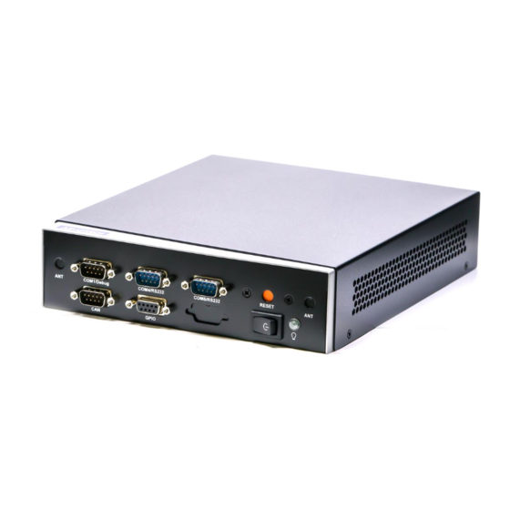
The following sections show the external connectors and pin assignments for appli- cations. EPC-R6410 IO Overview Debug port Antenna( Reserved) RS232 RS232 Reset Antenna(Reserved) GPIO Power bu on Line out RS232 RS232/422/485 Giga LAN Antenna (Reserved) Antenna (Reserved) DC-IN HDMI SD slot SIM slot EPC-R6410 Android User Manual... -
Page 13: Connectors
Here is reset button for system reset. 2.3.3 COM1/Debug COM1 of EPC-R6410 can be used as RS232 and Debug port by jumper select and default setting as debug port. You can set CN18 on board to configure the work mode. Pins are defined below Table 2.1: COM1 pin define... -
Page 14: Com4/Com5/Com2 Rs232
(1-2) COM0 is debug port (default) (2-3) COM0 is RS232 COM port 2.3.4 COM4/COM5/COM2 RS232 EPC-R6410 supports 3 x RS232 with 4wires, as COM2, COM4, COM5. Pins are defined below: Description COM2_RX COM2_TX COM2_RTS COM2_CTS COM port EPC-R6410 Android User Manual... - Page 15 Table 2.2: COM4 pin define Description Table 2.3: COM5 pin define Description EPC-R6410 Android User Manual...
-
Page 16: Can
2.3.5 EPC-R6410 supports 1xCAN; pins defined below: Table 2.4: CAN Description CAN_D+ CAN_D- 2.3.6 GPIO EPC-R6410 supports 8 x GPIO via a DB9 connector. Pins are defined below: Table 2.5: GPIO Description GPIO0 GPIO1 GPIO2 GPIO3 GPIO4 GPIO5 GPIO6 +V_GPIO... -
Page 17: Dc-In
2.3.7 DC-In EPC-R6410 support 12V DC in by DC-Jack. 2.3.8 Antenna Here are total four reserved openings for antenna to support Wi-Fi/3G/4G modules. 2.3.9 COM3 RS232/422/485 COM3 can be configure to RS232 or RS422 or RS485 by jumper. You can set CN26 and JSETCOM1 and J422T1 and J384T1 to select the work mode. - Page 18 RS232 mode (CN26 must be set RS232 at the same time) (default) 13-15 14-16) (3-4 9-11 10-12 RS422 mode 15-17 16-18) (1-2 9-11 10-12 RS485 mode (CN26 must be set RS485 at the same time) 15-17 16-18) EPC-R6410 Android User Manual...
- Page 19 J485t1 COM3 RS-485 impedance select Part Number 1653003201-01 Footprint HD_3x2P_79_D_PRX Description PIN HEADER 2X3P 2.00mm 180D(M) DIP 1140-010-06SN Setting Function (1-3,2-4) Impedance On (default) (3-5,4-6) Impedance off This pin header is designed for RS485 impedance on/off. EPC-R6410 Android User Manual...
-
Page 20: Hdmi
2.3.10 HDMI EPC-R6410 supports HDMI; pin definition below: Description Description HDMI_Z_TD2_P HDMI_Z_CLK_N HDMI_Z_TD2_N HDMI_CEC_OUT HDMI_Z_TD1_P HDMI_DDC_CLK HDMI_Z_TD1_N HDMI_DDC_DAT HDMI_Z_TD0_P +5V_HDMI HDMI_Z_TD0_N HDMI_HPD_OUT HDMI_Z_CLK_P EPC-R6410 Android User Manual... -
Page 21: Vga
2.3.11 EPC-R6410 supports VGA; pin definitions below: Description Description VGA_b_R +5V_CRT VGA_b_G VGA_b_B VGA_b_DDC_DAT VGA_b_HSYNC VGA_b_VSYNC VGA_b_DDC_CLK EPC-R6410 Android User Manual... -
Page 22: Lan
2.3.12 EPC-R6410 supports Ethernet; pin definitions below Description GBE_MDI0_P GBE_MDI0_N GBE_MDI1_P GBE_MDI1_N GBE_MDI2_P GBE_MDI2_N GBE_MDI3_P GBE_MDI3_N LAN1_ACT +3.3V LAN1_1000_LINK LAN1_100_LINK Ethernet Connector EPC-R6410 Android User Manual... -
Page 23: Usb
2.3.13 EPC-R6410 supports 6 x USB2.0 type A connectors Description +5V_USB_P56_B USB_P6L_N USB_P6L_P USBV56_GND +5V_USB_P56_B USB_P5L_N USB_P5L_P USBV56_GND Description +5V_USB_P12_B USB_P1L_N USB_P2L_P USB_12_GND +5V_USB_P12_B USB_P2L_N USB_P2L_P USB_12_GND +5V_USB_P34_B USB_P3L_N USB_P3L_P EPC-R6410 Android User Manual... -
Page 24: Audio Jack
USB_34_GND +5V_USB_P34_B USB_P4L_N USB_P4L_P USB_34_GND USB port connector 2.3.14 Audio Jack ECP-R6410 supports 1 Line out and 1 Mic in Description HPOUT_L lLINEOUT_DETECT HPOUT_R EPC-R6410 Android User Manual... -
Page 25: Quick Start Guide
Open HyperTerminal on your Windows PC, and select the settings as shown in Figure 2-7. After the bootloader is programmed on SD card, insert power adapter connector to DC jack on EPC-R6410 to power up the board. The bootloader prompt is dis- played on the terminal screen. EPC-R6410 Android User Manual... - Page 26 Figure 2.1 HyperTerminal Settings for Terminal Setup EPC-R6410 Android User Manual...
-
Page 27: Chapter 3 Software Functionality
Chapter Software Functionality This chapter details the software programs on the EPC-R6410 plat- form. -
Page 28: Test Tools
Test Tools All test tools must be verified on EPC-R6410 Evaluation kit, please prepare the required test fixtures before verifying each specified I/O. If you have any problem get- ting the test fixture, please contact your Advantech contact window for help. -
Page 29: Sd Test
01887800 30 31 32 33 34 35 36 37 38 39 41 42 43 44 45 46 |0123456789ABCDEF| Note! Please make sure parameter “seek” is equal to 25118 as indicated in the above codes. If you create the file to a wrong sector, it may damage the system. EPC-R6410 Android User Manual... -
Page 30: Gpio Test
GPIO Test EPC-R6410 GPIO default setting Android OS EPC-R6410 Default direction /sys/class/gpio/ GPIO0 gpio2 GPIO1 gpio3 GPIO2 gpio4 GPIO3 gpio 5 GPIO4 gpio6 GPIO5 gpio7 GPIO6 gpio8 GPIO7 gpio9 GPIO8 gpio10 GPIO9 gpio11 GPIO10 gpio12 GPIO11 gpio13 GPIO12 gpio14 GPIO13... -
Page 31: I2C Test
I2C Test There is one I2C bus in EPC-R6410. # ls /sys/class/i2c-dev i2c-0 i2c-1 i2c-2 # i2cdetect -l i2c-0 i2c imx-i2c I2C adapter i2c-1 i2c imx-i2c I2C adapter i2c-2 i2c imx-i2c I2C adapter Please try the command below to check if there is any device connected to i2c bus 1. -
Page 32: Lan Test
If you would like to config IP manually, please use the command below: # busybox ifconfig eth0 xxx.xxx.xxx.xxx up Here is a real case for your reference. The host (EPC-R6410) IP is 192.168.0.10; the target (a desktop computer) IP is 192.168.0.12 #busybox ifconfig eth0 down # busybox ifconfig eth0 192.168.0.10 up... -
Page 33: Uart Test
The target computer (Client) firewall need close. UART Test As you can see below, there are 5 UARTs supported by EPC-R6410. /dev/ttymxc0 is reserved for EPC-R6410 debug port, the rest of the UART ports can be applied by the user. UART1/UART2/UART3/UART4 connect to loopback. DEVICE... -
Page 34: Can Test
Prepare one Advantech PCI-1680U Can card and install the driver. Connect EPC-R6410 CAN port CAN1_D+ /CAN1_D- and GND with Advantech PCI-1680U Can card. Use the following command under EPC-R6410 to send data through to the Can card. # cansend can0 0x01 0x02 0x03... -
Page 35: Display Output Setting
Use the following command under EPC-R6410 to receive data form the oppo- site side: # candump interface = can0, family = 29, type = 3, proto = 1 3.10 Display Output Setting Please set the U-boot environment as shown below 3.10.1... -
Page 36: Dual Display Settings
LVDS (Dual Channel 21inch) and VGA clone out, please set U-boot as shown below: setenv bootargs console=ttymxc0,115200 androidboot.console=ttymxc0 vmalloc=400M init=/init video_mode=extension video=mxcfb0:dev=ldb,LDB-1080P60,if=RGB24,bpp=32 ldb=spl0 video=mxcfb1:dev=lcd,1920x1080M@60,bpp=32 video=mxcfb2:off video=mxcfb3:off fbmem=28M,28M androidboot.hardware=freescale pcie_testmode=off EPC-R6410 Android User Manual... -
Page 37: Triple Display Settings
3.10.3 Triple Display Settings LVDS (Single Channel 7inch), HDMI and VGA clone out, please set U-boot as shown below: setenv bootargs console=ttymxc0,115200 androidboot.console=ttymxc0 vmalloc=400M init=/init video=mxcfb0:dev=ldb,LDB-800X480,if=RGB666,bpp=24 video=mxcfb1:dev=hdmi,1920x1080M@60,bpp=24 fbmem=28M,28M androidboot.hardware=freescale pcie_testmode=off EPC-R6410 Android User Manual... - Page 38 EPC-R6410 Android User Manual...
-
Page 39: Android Os
Chapter Android OS This chapter introduces how to build an Android system and develop it, based on our Android system. -
Page 40: Introduction
EPC-R6410 supports Linux host only, so try- ing to develop an EPC-R6410 app on Windows/Android host PC will fail. For now the official supported host version is Ubuntu 14.04 64-bit; host PCs in any other version may have compatibility issues. -
Page 41: Set Up Build Environment
Before building an Android system, you need setup the toolchain. Android toolchain is under android/prebuilds. Please refer to 4.2.1 Setup the toolchain path to point to arm-eabi- tools in android/prebuilds/gcc/linux- x86/arm/arm-eabi-4.6/bin,the command is: root@PcName:~# export PATH=$ANDROID_DIR/android/prebuilts/gcc/linux-x86/arm/arm-eabi-4.6/bin:$PATH EPC-R6410 Android User Manual... -
Page 42: Build Instructions
Open a terminal console and change directory to BSP scripts folder Perform the following command: root@PcName:~# ./mk_android.sh <product name> where <product name> is: • EPC-R6410 for EPC-R6410 board Then you can get android all image file under image folder, include as follows u- boot_crc.bin, u-boot_crc.bin.crc, boot.img, system.img, recovery.img. 4.4.2... -
Page 43: Build Android Ota Package
Insert one SD card into your development computer Check the SD card location, like /dev/sdb root@PcName:~# cd ./ EPC-R6410AIVxxxx_yyyy-mm-dd/scripts root@PcName:~#./mksd-android.sh /dev/sdb Then insert the SD card to EPC-R6410 and power up, it should boot up with an Android environment. EPC-R6410 Android User Manual... -
Page 44: Transfer The Whole System To Onboard Emmc
Boot up from the SD card Perform the following command: root@PcName:~# cd /data/mkimage /scripts root@PcName:~# ./mkmmc?android.sh /dev/block/mmcblk0 Remove the SD card, then EPC-R6410 can boot up from the onboard eMMC. Customization 4.7.1 Config Android Kernel Open a terminal console and change directory to BSP scripts folder... -
Page 45: Put Source Code Into System
LOCAL_PACKAGE_NAME := PROJECT_NAME_HERE LOCAL_CERTIFICATE := platform include $(BUILD_PACKAGE) # Use the following include to make our test apk. include $(call all-makefiles- under,$(LOCAL_PATH)) Edit following file: ./android/device/Advantech/EPC-R6410/device.mk to insert correct project name: PRODUCT_PACKAGES += \ PROJECT_NAME_HERE\ librxtxSerial\ SerialJ EPC-R6410 Android User Manual... -
Page 46: Serial Port Test
Serial Port Test 4.8.1 Setup Serial Port Click on the Serial Port. Click Setup. EPC-R6410 Android User Manual... -
Page 47: Console Test
115200 8N1, and opening serial terminal AP (like minicom, putty or teraterm) Click Console. After typing some characters (e.g., "This is a test. 123456789ABCDEF") and press- ing Enter in serial terminal AP, an identical message will be displayed in the reception block, as shown below: EPC-R6410 Android User Manual... -
Page 48: Loopback Test
Use a serial cable to connect ttymxc1 with PC/NB's serial port that should be configured to 115200 8N1, and open a serial terminal AP (like minicom, putty or teraterm) Click Send01010101. The character "U" (b'01010101) will be displayed continuously, as shown below: EPC-R6410 Android User Manual... -
Page 49: Network Setup
Network Setup 4.9.1 Wi-Fi Click Settings. Turn Wi-Fi on. EPC-R6410 Android User Manual... - Page 50 Choose ESSID (for example, Advantech for guest Testing) Input correct password. EPC-R6410 Android User Manual...
- Page 51 Wi-Fi Authenticating/Connecting/Obtaining IP address Wi-Fi connected EPC-R6410 Android User Manual...
-
Page 52: Bluetooth
4.9.2 Bluetooth Click Settings, switch the Bluetooth switch to ON to Turn on Bluetooth: Click Settings / Bluetooth for bluetooth main interface: EPC-R6410 Android User Manual... - Page 53 Click "iMX6" to let EPC-R6410 bluetooth be visible to other Bluetooth devices Click any available devices to pair with it: After pairing successfully with another Bluetooth device, you can communicate with it. EPC-R6410 Android User Manual...
-
Page 54: Ethernet
If you can't connect to the network, please check the following settings: A. Settings/More/Mobile networks/Data enabled, then Enabled. B. Settings/More/Mobile networks/Access Point Names, then Correct. 4.9.4 Ethernet Click Settings / Ethernet configuration, then turn on Ethernet Click Ethernet configuration. EPC-R6410 Android User Manual... -
Page 55: Can Test
Choose Connection Type (DHCP or Static IP) 4.10 Can Test Click Flexcan. Edit "interface","ID"and"Data", then click "Send" to send data through the Can port. EPC-R6410 Android User Manual... -
Page 56: System Update
Refer to section 4.4.5 to build OTA package. Insert your u disk. Note! Make sure your u disk is FAT32 and has an update.zip file under the first partition, such as /dev/sdb1. Click Settings / About tablet / Addition system updates. EPC-R6410 Android User Manual... -
Page 57: System Reset
Wait for a moment; the system will reboot for updating It will take some time to update. 4.12 System Reset Factory data reset Click settings / backup & reset, then enter into main interface. Click Factory data reset. EPC-R6410 Android User Manual... - Page 58 Click Reset to erase all data on the tablet. Click Erase everything. 5. Wait for a moment; the system will reboot and erase all user data. EPC-R6410 Android User Manual...
-
Page 59: Watchdog Function
Edit init.rc(you can find it under android_source _code/ device/fsl/EPC- R6410/init.rc) ,find follow line: # [Advantech]Set watchdog timer to 30 seconds and pet it every 10 seconds to get a 20 seconds margin service watchdogd /sbin/watchdogd 10 20... - Page 60 EPC-R6410 Android User Manual...
-
Page 61: Advantech Services
Chapter Advantech Services This chapter introduces Advan- tech Design-in service, technical support and warranty policy for EPC-R6410 evaluation kit. -
Page 62: Risc Design-In Services
Easy Development Advantech offers firmware support, root file-system, BSP and other develop tools. It helps customers to easily develop their carrier board and differentiate their embed- ded products and applications. - Page 63 Advantech has been involved in the industrial computer industry for many years and found that customers usually have the following questions when implementing modu- lar designs.
- Page 64 RISC COM. Design stage When a product moves into the design stage, Advantech will supply a design guide of the carrier board for reference. The carrier board design guide provides pin defini- tions of the COM connector with limitations and recommendations for final design, so customers can have a clear guideline to follow during their carrier board develop- ment.
-
Page 65: Contact Information
RISC platforms usually have less support for ready-made drivers on the carrier board, therefore the customer has to learn from trial and error and finally get the best solution with the least effort. Advantech’s team has years of experience in customer support and HW/SW development knowledge. Conse- quently, we can support customers with professional advice and information as well as shortening development time and enabling more effective product integration. -
Page 66: Global Service Policy
(Dead-on-Arrival). The DOA Cross-Shipment excludes any shipping damage, cus- tomized and/or build-to-order products. For those products which are not DOA, the return fee to an authorized ADVANTECH repair facility will be at the customers' expense. The shipping fee for reconstructive products from ADVANTECH and back to the customers' site will be at ADVANTECH's expense. -
Page 67: Repair Process
"Problem Description". Vague entries such as "does not work" and "failure" are not acceptable. If you are uncertain about the cause of the problem, please contact ADVANTECH's Application Engineers (AE). They may be able to find a solution that does not require sending the product for repair. - Page 68 Product updates and tests upon the request of customers who are without war- ranty. If a product has been repaired by ADVANTECH, and within three months after such a repair the product requires another repair for the same problem, ADVANTECH will do this repair free of charge.
- Page 69 5.3.2.6 Shipping Back to Customer The forwarding company for RMA returns from ADVANTECH to customers is selected by ADVANTECH. Per customer requirement, other express services can be adopted, such as UPS, FedEx and etc. The customer must bear the extra costs of such alternative shipment.
- Page 70 No part of this publication may be reproduced in any form or by any means, electronic, photocopying, recording or otherwise, without prior written permis- sion of the publisher. All brand and product names are trademarks or registered trademarks of their respective companies. © Advantech Co., Ltd. 2017...
Need help?
Do you have a question about the EPC-R6410 and is the answer not in the manual?
Questions and answers