
Related Manuals for Advantech ECU-479 Series


Summary of Contents for Advantech ECU-479 Series
- Page 1 User Manual ECU-479 Series IEC-61850 Power Substation 2U Rackmount Server with ® Intel 12th Generation Processor...
- Page 2 No part of this manual may be reproduced, copied, translated, or transmitted in any form or by any means without the prior written permission of Advantech Co., Ltd. The information provided in this manual is intended to be accurate and reliable.
- Page 3 Product Warranty (2 years) Advantech warrants the original purchaser that each of its products will be free from defects in materials and workmanship for two years from the date of purchase. This warranty does not apply to any products that have been repaired or altered by persons other than repair personnel authorized by Advantech, or products that have been subject to misuse, abuse, accident, or improper installation.
- Page 4 This product has passed the CE test for environmental specifications when shielded cables are used for external wiring. We recommend the use of shielded cables. This type of cable is available from Advantech. Please contact your local supplier for ordering information.
- Page 5 The sound pressure level at the operator's position according to IEC 704-1:1982 should be no more than 70 dB (A). DISCLAIMER: This set of instructions is given according to IEC 704-1. Advantech disclaims all responsibility for the accuracy of any statements contained herein.
- Page 6 Ce produit est destiné à être alimenté par le secteur CA ou une source d'alimen- tation nominale CC 100-240 V, 3,0 A minimum, Tma 50 degrés C minimum, si besoin d'aide supplémentaire, veuillez contacter Advantech pour plus d'informa- tions. Éloignez le cordon d'alimentation des zones à fort trafic. Ne placez rien dessus le cordon d'alimentation.
- Page 7 La pression sonore niveau au poste de l'opérateur selon CEI 704-1:1982 ne doit pas être plus supérieur à 70 dB(A). AVIS DE NON-RESPONSABILITÉ: cet ensemble d'instructions est fourni conformé- ment à la norme CEI 704-1. Advantech décline toute responsabilité quant à l'exacti- tude des déclarations contenues dans ce document. ECU-479 User Manual...
- Page 8 ECU-479 User Manual viii...
-
Page 9: Table Of Contents
System Hardware ................. 3 1.2.3 I/O Interface .................. 3 1.2.4 Environment.................. 3 Function Block Diagram ................4 Figure 1.1 ECU-479 Series Product Function Block....4 Safety Precautions ..................4 Chassis Dimensions.................. 5 Figure 1.2 ECU-479 Chassis Dimensions ........5 Packing List....................5 Chapter Hardware Specifications .....7... - Page 10 2.11.1 Compatible with Intel® 13th/12th Gen Intel® Core™ CPU ..19 Table 2.9: Validated 13th/12th Gen Intel® Core™....19 2.12 Memory ....................19 2.12.1 Validated Memory............... 19 Table 2.10:Validated Memory ............ 19 2.13 TPM ......................20 2.14 Platform Feature Description ..............20 2.14.1 BIOS ...................
- Page 11 Figure 3.41Express Root Port ............ 52 Figure 3.42SATA and RST Configuration........53 Figure 3.43Security Configuration ..........54 Figure 3.44HD Audio Configuration..........55 3.2.4 Security ..................56 Figure 3.45Security..............56 3.2.5 Boot..................... 57 Figure 3.46Boot ................57 3.2.6 Save & Exit ................. 58 Figure 3.47Save &...
- Page 12 ECU-479 User Manual...
-
Page 13: Chapter 1 Overview
Chapter Overview This chapter provides an overview of the ECU-479 Series specifica- tions. Sections include: Introduction Hardware Specifications Safety Precautions Function Block Diagram Chassis Dimensions Packing List... -
Page 14: Introduction
To fulfill the per- formance requirements of modern distributed software applications which require fast processing, Advantech offers ECU-479 which is targeted at advanced server-level data concentrators and protocol converters in scenarios like substation automation, energy management, secondary communication and control, etc. -
Page 15: Hardware Specifications
Hardware Specifications 1.2.1 General Certifications: CE, FCC Class A, IEC61850-3, IEEE 1613 Dimensions (W x D x H): 483 x 478 x 88 mm Enclosure: SECC & Aluminum Mounting: 2U 19” Rackmount Power Requirements: – –... -
Page 16: Function Block Diagram
Caution! Always ground yourself to remove any static electric charge before touching the ECU-479 series. Modern electronic devices are very sensi- tive to static electric charges. Use a grounding wrist strap at all times. -
Page 17: Chassis Dimensions
Débranchez toutes les sources d'alimentation Chassis Dimensions 482.60 465.10 Figure 1.2 ECU-479 Chassis Dimensions Packing List The package of the ECU-479 Series contains the following items: The main ECU-479 unit Accessory box (screws, jumpers, 1 x Startup Manual) 1 x warranty card ... - Page 18 ECU-479 User Manual...
-
Page 19: Chapter 2 Hardware Specifications
Chapter Hardware Specifications Sections include: Overview Front Elements (LED, FAN, SATA Slots) Power Input Ethernet Interface (On-Board) Display Interface USB Expansion Functions Storage (SATA, M.2) Processors Memory TPM Platform Features Description ... -
Page 20: Overview
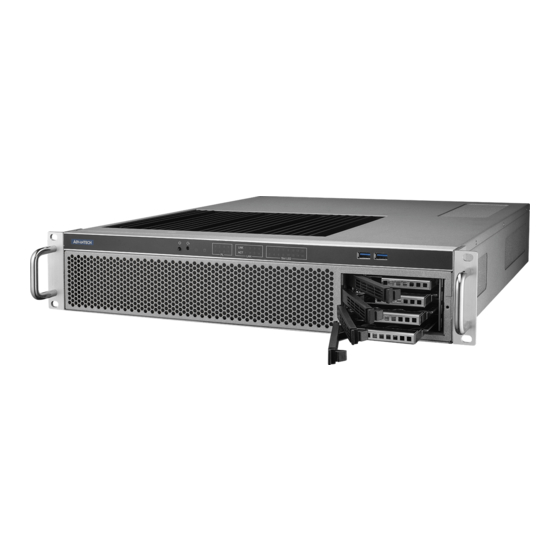
Overview 2.1.1 ECU-479 LED and Interface Figure 2.1 ECU-479 Front Panel Figure 2.2 ECU-479 Rear Panel Front Elements 2.2.1 LED Indicators The LEDs on the front panel can be divided into 4 groups. 2.2.1.1 System Status Indicators SATA Table 2.1: Definition of System Status Indicators Status Description Green... - Page 21 2.2.1.3 Programmable LED The ECU-479 Series products provide 8 programmable LED indicators which are convenient for users to control the programmable LED state (green, off) using API programming. They can be used to indicate and edit the machine’s operating status.
- Page 22 2.2.1.4 Slot LED The Slot LED is different according to the corresponding expansion card. Here, we take the LED definition of UNOP-1514RE/PE as an example to show how it is defined. Other LEDs are defined according to the description of the relevant expan- sion card and manual.
-
Page 23: Disk Bay
2.2.2 Disk Bay ECU-479 supports four swappable 2.5” SSDs at the front. Follow these steps below to install an SSD: Remove the baffle on the right of the front panel, and pull out the disk tray. Figure 2.3 Removing the SATA Baffle ECU-479 User Manual... - Page 24 Fix the SATA disk onto the tray and push it back into the disk bay. Then attach the baffle in front of the SATA bay. Figure 2.4 Fixing the SATA Disk onto the Disk Tray ECU-479 User Manual...
-
Page 25: Jumpers And Connectors
Jumpers and Connectors The tables below list the function of each of the jumpers and connectors. Later sec- tions in this chapter give instructions on setting jumpers that are used to configure your system for your application Table 2.5: Jumpers Label Function JCMOS1... -
Page 26: Board Layout: Jumper And Connector Locations
JUSB_2 DIMMB1 JFP1+JFP2 JFP3 JWDT1+JOBS1 USB4,5 Figure 2.5 Jumper and Connector Locations Power Input The ECU-479 Series products support redundant power input for both A/C and D/C. Table 2.7: Power Input Item AC/DC Voltage Range Power Rating Installation 100-240 V... -
Page 27: Ethernet Interface
Ethernet Interface The ECU-479 Series products are equipped with Intel® 4 x Giga LAN. LAN1 port is shared with the iBMC function. LAN2 port is shared with the IAMT function. 2.6.1 MAC Address You can identify MAC addresses according to the labels placed on Ethernet connec- tors as shown below. -
Page 28: Usb Ports
ECU-479 supports 1 standard domain I/O expansion. Customers can choose differ- ent proprietary PCI/PCIe cards from the following Table 2.7.1.2 according to their needs. Through the interface card, the ECU-479 Series can also use standard PCI cards, PCIe cards, mini-PCI cards, as well as PCI-104 cards. 2.9.1.2... -
Page 29: Pcie Expansion Cards
2.9.2 PCIe Expansion Cards 2.9.2.1 PCIe Expansion Card Illustration ECU-479 supports 4 low-profile PCIe cards. The size limitation is shown below: Figure 2.9 PCIe Card Dimension Limitation Figure 2.10 PCIe Card Position on the Main Board ECU-479 User Manual... -
Page 30: Storage (Sata, M.2)
Part Number Description Quad Port Copper Gigabit Ethernet PCI Express Server Adapter PCIE-1130PS-00A1E ® with Intel I350 (Advantech Form Factor) Quad Port Fiber Gigabit Ethernet PCI Express Server Adapter with PCIE-2130NP-00A1E ® Intel I350 Quad Port Fiber 10GbE Ethernet PCI Express Server Adapter with PCIE-2230NP-00A1E ®... -
Page 31: Processors
2.10.2 M.2 Storage The M.2 2280 connector supports both SATA and PCIe SSD devices for higher read/ write speeds. M2_2280_1 Figure 2.11 M.2 Connector Position on the Main Board 2.11 Processors 2.11.1 Compatible with Intel® 13th/12th Gen Intel® Core™ CPU ECU-479 is equipped with one CPU socket to support 13th/12th Gen Intel®... - Page 32 ECC memory modules with a maximum total capacity of 64 GB (maximum 32 GB for each SODIMM). 2.12.1 Validated Memory Advantech has tested a list of RAM for your reference, and these are verified as com- patible with ECU-479 under our test. Table 2.10: Validated Memory Brand...
- Page 33 2.14 Platform Feature Description 2.14.1 BIOS With the AMI BIOS Setup program, you can modify BIOS settings and control the special features of your computer. The Setup program uses a number of menus for making changes and turning special features on or off. This chapter describes the basic navigation of the ECU-479 Setup screens.
- Page 34 To get the driver and test case for Windows and Linux operating systems, you can visit the official Advantech website on the ECU-479 product page to download the driver with the test sample.
- Page 35 Chapter BIOS Operation...
- Page 36 Introduction With the AMI BIOS Setup Utility, you can modify BIOS settings and control the spe- cific features of your computer. The Setup Utility uses a number of menus for making changes and turning the specific features on or off. This chapter describes the basic navigation of the ECU-479 setup screens.
- Page 37 Entering BIOS Setup Press <DEL> at bootup to enter AMI BIOS Setup Utility, the Main Menu will appear on the screen. Use arrow keys to select among the items and press <Enter> to accept or enter the sub-menu. 3.2.1 Main Menu When users first enter the BIOS Setup Utility, they enter the Main setup screen.
- Page 38 3.2.2 Advanced BIOS Features Setup Select the Advanced tab from the ECU-479 setup screen to enter the Advanced BIOS setup screen. You can select any of the items in the left frame of the screen, such as CPU configuration, to go to the sub menu for that item. You can display an Advanced BIOS Setup option by highlighting it using the keys.
- Page 39 3.2.2.1 Platform Misc Configuration Figure 3.4 Platform Misc Configuration Native PCIE Enable "Enable or Disable" PCI Express native support. 3.2.2.2 CPU Configuration Figure 3.5 CPU Configuration ECU-479 User Manual...
- Page 40 Figure 3.6 Performance-core Information Performance-core Information Performance-core (P-core) information of current CPU used is displayed here. Hardware Prefetcher Hardware Prefetcher is a technique that fetches instructions and/or data from memory into the CPU cache memory well before the CPU needs it to improve the load-to-use latency.
- Page 41 3.2.2.3 Power & Performance Figure 3.7 Power & Performance Figure 3.8 CPU - Power Management Control Boot Performance Select the performance state that the BIOS will set before OS handoff. Intel® Speedstep™ Allows more than two frequency ranges to be supported. ECU-479 User Manual...
- Page 42 Turbo Mode "Enable or Disable" processor turbo mode. C states Intel® C states setting for power saving. Suggest enable for ErP. 3.2.2.4 PCH-FW Configuration Figure 3.9 PCH-FW Configuration Boot Performance PCH-FW Version PCH-FW page shows Intel® ME FW information. ECU-479 User Manual...
- Page 43 AMT Configuration Figure 3.10 AMT Configuration ASF Configuration Figure 3.11 ASF Configuration – PET Progress "Enable or Disable" PET events Progress to receive PET events.ASF Config- uration ECU-479 User Manual...
- Page 44 – WatchDog “Enable or Disable” Watchdog Timer. – ASF Sensors Table "Enable or Disable" to add ASF Sensor Table into ASF ACPI Table. Secure Erase Configuration Figure 3.12 Secure Erase Configuration – Secure Erase mode Change Secure Erase module behavior as “Simulated or Real”. –...
- Page 45 Firmware Update Configuration Figure 3.13 Firmware Update Configuration – ME FW Image Re-flash "Enable or Disable" ME firmware image re-flash function. PTT Configuration Figure 3.14 PTT Configuration ECU-479 User Manual...
- Page 46 PTT (Intel Platform Trust Technology) is a firmware TPM. 3.2.2.5 Trusted Computing Figure 3.15 TPM Settings Security Device Support “Enable or Disable” TPM Support. You can purchase an Advantech-designed dTPM 2.0 module to enable TPM function. P/N: PCA-TPMSPI-00A1. ECU-479 User Manual...
- Page 47 3.2.2.6 ACPI Settings Figure 3.16 ACPI Settings Enable ACPI Auto Configuration "Enable or Disable" ACPI auto configuration. Enable Hibernation "Enable or Disable" Hibernation (OS/S4 Sleep State). This option may not be applied in some OS. ACPI Sleep State ...
- Page 48 3.2.2.7 SMART Settings Figure 3.17 SMART Settings SMART Self Test "Enable or Disable" SMART Self Test on all HDDs during POST. 3.2.2.8 NCT6126D Super IO Configuration Figure 3.18 NCT6126D Super IO Configuration ECU-479 User Manual...
- Page 49 Serial Port 1,2 Configuration Figure 3.19 Serial Port 1 Configuration – Serial Port "Enable or Disable" serial port . – Change Settings Select an optimal setting for serial port 3. – Device Mode Default for this Device Mode is "RS-232". ECU-479 User Manual...
- Page 50 3.2.2.9 Hardware Monitor Figure 3.20 Hardware Monitor Case Open Warning "Enable or Disable" the Chassis Intrusion monitoring function. When it is enabled and the case is opened, the speaker beeps. CPU Warning Temperature Use this item to set the CPU warning temperature. When the system reaches the warning temperature, the speaker will beep.
- Page 51 3.2.2.10 S5 RTC Wake Settings Figure 3.21 S5 RTC Wake Settings Wake system with Fixed Time "Enable or Disable" System wake on alarm event. The system will wake on the hr:min:sec as specified. 3.2.2.11 iBMC Configuration Figure 3.22 iBMC Configuration ECU-479 User Manual...
- Page 52 iBMC “Enable or Disable” iBMC controller’s hardware communication. The default set- ting is “Enabled”. iBMC controller/function can be disabled if the item is selected as “Disabled”. 3.2.2.12 Serial Port Console Redirection Figure 3.23 Serial Port Console Redirection Figure 3.24 Legacy Console Redirection Settings ECU-479 User Manual...
- Page 53 COM1 – Console Redirection Settings Console Redirection “Enable or Disable”. Legacy Console Redirection – Legacy Console Redirection Settings Select a COM port to display redirection of Legacy OS and Legacy OPROM Messages. Serial Port for Out-of-Band Management/ Windows Emergency Manage- ...
- Page 54 3.2.2.14 USB Configuration Figure 3.26 USB Information Legacy USB Support This supports USB device under legacy OS such as DOS. When choosing "AUTO", the system will automatically detect if any USB device is plugged into the computer and enable USB legacy mode when a USB device is plugged in and disable USB legacy mode when no USB device is plugged in.
- Page 55 3.2.2.15 Network Stack Configuration Figure 3.27 Network Stack Configuration Network Stack "Enable or Disable" UEFI Network Stack. 3.2.2.16 CSM Configuration Figure 3.28 CSM Configuration ECU-479 User Manual...
- Page 56 Figure 3.29 CSM Configuration (CSM Support "Enabled") Compatibility Support Module Configuration – CSM Support "Enable or Disable" CSM Support. The default setting is "Disabled". If your graphics card does not support UEFI mode, make sure to select "Enabled" to allow non-UEFI boot mode before installing the graphics card to turn on the computer.
- Page 57 3.2.2.17 NVMe Configuration Figure 3.30 NVMe Configuration NVMe Configuration Supports NVMe M.2 storage device. 3.2.2.18 Driver Health Figure 3.31 Driver Health ECU-479 User Manual...
- Page 58 3.2.3 Chipset Figure 3.32 Chipset This page provides information on the ECU-479 chipset. 3.2.3.1 System Agent (SA) Configuration Figure 3.33 System Agent (SA) Configuration ECU-479 User Manual...
- Page 59 VT-d "Enable or Disable" VT-d function. Above 4GB MMIO BIOS assignment "Enable or Disable" above 4GB MemoryMappedIO BIOS assignment. 3.2.3.2 Memory Configuration Figure 3.34 Memory Configuration Maximum Memory Frequency Maximum memory frequency selections in MHz. ECU-479 User Manual...
- Page 60 3.2.3.3 Graphics Configuration Figure 3.35 Graphics Configuration Primary Display Set Primary Display to "Auto", "IGFX", "PEG", "PCI", or "SG". Internal Graphics Set Internal Graphics to "Auto", "Disable" or "Enable". "Auto" will disable inter- nal graphics when a GPU card is installed. If GPU and internal graphics outputs are required at the same time, set this item to "Enable".
- Page 61 3.2.3.4 VMD Setup Menu Figure 3.36 Graphics Configuration Primary Display Set Primary Display to "Auto", "IGFX", "PEG", "PCI", or "SG". Internal Graphics Set Internal Graphics to "Auto", "Disable" or "Enable". "Auto" will disable inter- nal graphics when a GPU card is installed. If GPU and internal graphics outputs are required at the same time, set this item to "Enable".
- Page 62 3.2.3.5 PCI Express Configuration Figure 3.37 PCI Express Configuration Figure 3.38 PCI Express Root Port (PCIe1) PCI Express Root Port (PCIe1) – PCI Express Root Port (PCIe1) "Enable or Disable” PCI Express root port. ECU-479 User Manual...
- Page 63 – PCIe Speed Select "Auto, Gen1, Gen2, Gen 3, Gen 4" for PCIe Speed. 3.2.3.6 PCH-IO Configuration Figure 3.39 PCH-IO Configuration LAN1~4 Controller "Enable or Disable" LAN1~4 controller. LAN1~4 Option-ROM "Enable or Disable" LAN1~4 boot option for legacy network devices. PCIE Wake ...
- Page 64 3.2.3.7 PCI Express Configuration Figure 3.40 PCI Express Configuration Figure 3.41 Express Root Port PCI Express Root Port 1 "Enable or Disable" PCI Express Root Port. PCIe Speed Select "Auto, Gen1, Gen2, Gen 3" for PCIe Speed. ECU-479 User Manual...
- Page 65 Detect Non-compliance Device If enable, it will take more time at POST time. 3.2.3.8 SATA and RST Configuration Figure 3.42 SATA and RST Configuration SATA Controller(s) "Enable or Disable" SATA controller. SATA Mode Selection This is fixed as 'AHCI'. SATA Controller Speed ...
- Page 66 3.2.3.9 Security Configuration Figure 3.43 Security Configuration RTC Memory Lock Enable will lock bytes 38h-3Fh in the lower/upper 128-byte bank of RTC RAM. BIOS Lock "Enable or Disable" the PCH BIOS Lock Enable feature. Needs to be enabled to ensure SMM protection of flash.
- Page 67 3.2.3.10 HD Audio Configuration Figure 3.44 HD Audio Configuration HD Audio Control detection of the HD-Audio device. Disable = HDA will be unconditionally disabled. Enable=HDA will be unconditionally enabled. ECU-479 User Manual...
-
Page 68: Security
3.2.4 Security Figure 3.45 Security Select Security Setup from the ECU-479 BIOS setup menu. All Security Setup options, such as password protection and Secure Boot, are displayed in this section. Note! If only one user password is set, the user will have Administrator rights. Setting an administrator password is strongly recommended if you have security concerns. -
Page 69: Boot
3.2.5 Boot Figure 3.46 Boot Setup Prompt Timeout Directly key in the number, or use the <+> and <-> keys to adjust the number of seconds to wait for setup activation key. Bootup NumLock State Default state for the NumLock key during power on. Quiet Boot ... -
Page 70: Save & Exit
3.2.6 Save & Exit Figure 3.47 Save & Exit Save Changes and Exit When you complete system configuration, select this option to save your changes, exit BIOS setup and reboot the computer so the new system configuration parame- ters can take effect. Select Exit Saving Changes from the Exit menu and press <Enter>. -
Page 71: Appendix A I/O Pin Assignments
Appendix I/O Pin Assignments... -
Page 72: Lan1~Lan4
LAN1~LAN4 Pin1 Pin8 Table A.1: LAN Port (LAN1~LAN4) Signal Signal USB1~USB5 Pin 9 Pin 1 Table A.2: USB 3.2 Port (USB1~USB5) Signal Signal STDA_SSRX+ Shield GND_DRAIN STDA_SSTX- STDA_SSTX+ STDA_SSRX- ECU-470 User Manual... -
Page 73: Displayport Connector
DisplayPort Connector Table A.3: DisplayPort Connector (DP1~4) Signal Signal TMDS D2+ TMDS CLK- TMDS D2- TMDS D1+ TMDS D1- TMDS D0+ VCC (+5V) TMDS D0- Hot plug detect TMDS CLK+ COM1,2 Table A.4: RS-232 DB-9 Connector (COM1,2) RS-232 RS-485/422 Full Duplex RS-485 Half Duplex Data- Data+... -
Page 74: Spi_Tpm1
SPI_TPM1 Table A.5: Serial Peripheral Interface(SPI) Connector (SPI_TPM1) Signal Signal MISO PRSNT# N.C. IRQ# MOSI RESET# +3.3V POWER JFP1~JFP3 A.6.1 Power LED (JFP3) Table A.6: Power LED (JFP3) Function POWER_LED+ ECU-470 User Manual... -
Page 75: External Speaker Connector (Jfp2)
A.6.2 External Speaker Connector (JFP2) 1 4 7 10 Table A.7: External Speaker Connector (JFP2) Function EXTENAL_SPK_P1 EXTENAL_SPK_2 INTENAL_SPK_P3 INTENAL_SPK_P4 A.6.3 HDD LED Connector (JFP2) Table A.8: HDD LED Connector (JFP2) Signal HDD_LED+ HDD_LED- A.6.4 SMBus Connector (JFP2) 8 11 Table A.9: SMBus Connector (JFP2) Signal SMB_SNMP_SDAT... -
Page 76: Reset Connector (Jfp1)
A.6.6 Reset Connector (JFP1) 9 12 Table A.11: Reset Connector (JFP1) Signal SYSTEM RESET# CMOS clear (JCMOS1) and Intel® ME update (JME1) The ECU-479 motherboard contains a jumper that can erase CMOS data and reset the system BIOS information. Normally this jumper should be set with pins 1-2 closed. -
Page 77: Atx/At Mode Selection (Pson1)
Table A.13: WD timer output & OBS alarm (JWDT1+JOBS1) Function Jumper Setting Watchdog timer disable (2-4) 2-4, 8-10 closed OBS beep (8-10) *Watchdog timer reset (4-6) 4-6, 8-10 closed OBS beep (8-10) * default setting ATX/AT mode selection (PSON1) Table A.14: ATX/AT mode selection (PSON1) Function Jumper Setting AT mode... -
Page 78: Pcie Smbus Connection Setting Of Clock (Smb1, Smb3) And Data
A.11 PCIe SMBus connection setting of clock (SMB1, SMB3) and data (SMB2, SMB4) for PCIE1 ~ PCIE4 slots Some PCIe add-on cards or devices may have SMBus address conflicts with DIMMB2 slot at slave address of 0xA6. In the case, users may disable the SMBus connection of clock (SMB1, SMB3) and data (SMB2, SMB4), while VPD (Vital Prod- uct Data) will not be accessed. - Page 79 ECU-479 User Manual...
- Page 80 No part of this publication may be reproduced in any form or by any means, such as electronically, by photocopying, recording, or otherwise, without prior written permission from the publisher. All brand and product names are trademarks or registered trademarks of their respective companies. © Advantech Co., Ltd. 2023...
Need help?
Do you have a question about the ECU-479 Series and is the answer not in the manual?
Questions and answers