Table of Contents
Advertisement
Quick Links
Advertisement
Table of Contents

Related Manuals for Advantech ECU-150 Series


Summary of Contents for Advantech ECU-150 Series
- Page 1 User Manual ECU-150 Series...
- Page 2 No part of this manual may be reproduced, copied, translated, or transmitted in any form or by any means without the prior written permission of Advantech Co., Ltd. The information provided in this manual is intended to be accurate and reliable.
- Page 3 Product Warranty (2 years) Advantech warrants the original purchaser that each of its products will be free from defects in materials and workmanship for two years from the date of purchase. This warranty does not apply to any products that have been repaired or altered by persons other than repair personnel authorized by Advantech, or products that have been subject to misuse, abuse, accident, or improper installation.
- Page 4 In this event, users are required to correct the interference at their own expense. Technical Support and Assistance Visit the Advantech website at www.advantech.com/support to obtain the latest product information. Contact your distributor, sales representative, or Advantech's customer service center for technical support if you need additional assistance.
- Page 5 The sound pressure level at the operator's position according to IEC 704-1:1982 is no more than 70 dB (A). DISCLAIMER: This set of instructions is given according to IEC 704-1. Advantech disclaims all responsibility for the accuracy of any statements contained herein.
- Page 6 Do not touch any components on the CPU card or other cards while the PC is powered on. Disconnect the power before making any configuration changes. A sudden rush of power after connecting a jumper or installing a card may damage sensitive electronic components. ECU-150 Series User Manual...
-
Page 7: Table Of Contents
Wall-mounted and DIN-Rail Installation ........15 Figure 3.7 Wall-mount Bracket Installation ........ 15 Figure 3.8 Vertical DIN-Rail Bracket Installation......16 3.3.2 Installing a Wireless module Card and Antenna (Optional) ..16 Figure 3.9 Installing a Wireless module Card and Antenna..16 ECU-150 Series User Manual... - Page 8 ECU-150 Series User Manual viii...
-
Page 9: Chapter 1 Overview
Chapter Overview... -
Page 10: Introduction
-40~70°C. It offers Mini-PCIe and M.2 slot for integrating Wi-Fi/4G/5G modules. With Linux operating system and EdgeLink SDK, ECU-150 enable system integrators to develop applications precisely for solar power, electricity and factory, which require massive data collection, cloud based application and video related monitoring solu- tions. ECU-150 Series User Manual... -
Page 11: Specifications
Protocol Support: DNP3.0 Client & Server, OPC-UA Client & Server, BACNet/IP Client & Server, Modbus RTU/TCP Master & Slave, IEC-60870-5-101 Master, IEC-60870-5-103 Master, IEC-60870-5-104 Master & Slave PLC driver support: Siemens/Mitsubishi/Omron/Allen-Bradley, Delta etc 200+PLC drivers ECU-150 Series User Manual... -
Page 12: Environment
Caution! Always ground yourself to remove any static electric charge before touching ECU-150 Series. Modern electronic devices are very sensitive to static electric charges. Use a grounding wrist strap at all times. Place all electronic components on a static-dissipative surface or in a static- shielded bag. -
Page 13: Chassis Dimensions
Chassis Dimensions: Figure 1.1 ECU-150 Chassis Dimensions Packing List The accessory package of ECU-150 contains the following items: (A) ECU-150 (B) 1 x warranty card (C) Connector (D) Din-rail ECU-150 Series User Manual... - Page 14 ECU-150 Series User Manual...
-
Page 15: Chapter 2 Hardware Functionality
Chapter Hardware Functionality... -
Page 16: Overview
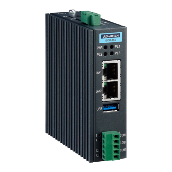
Overview The following figures show the panel configuration on ECU-150. More information of each peripheral is included in the following sections. Figure 2.1 ECU-150 Overview ECU-150 Series User Manual... -
Page 17: Led Status Indicators
The LEDs in the front panel can be divided into 4 groups: Figure 2.2 ECU-150 LED Status Indicator 2.2.1 System Status Indicators: Status Description Green Power is on Power is off Green Customers can define the Programmable LED state accord- IRIG ing to the actual need. ECU-150 Series User Manual... -
Page 18: Serial Communication Status Indicator
Blinking, Serial port 2 data being received 2.2.3 Ethernet Status Indicator Color Description Link1 Yellow Lighting, Ethernet not connected Act1 Green Blinking, Ethernet data being transmitted Link2 Yellow Lighting, Ethernet not connected Act2 Green Blinking, Ethernet data being transmitted ECU-150 Series User Manual... -
Page 19: Chapter 3 Wiring And Installation
Chapter Wiring and Installation... -
Page 20: Wiring
Power Input PWR V+ DC power input PIN PWR V- DC power input PIN 3.1.2 Communication Ports Figure 3.2 RS-232/485 Serial Ports (COM1~ COM2) Table 3.2: RS-232/485 Serial Ports (Pin Assignments) Pins RS-232 RS-485 Data+ Data- ECU-150 Series User Manual... -
Page 21: Wireless Card Installation
The installation is shown as below. Figure 3.3 USB Connector Table 3.3: USB Connector Pin Assignment Signal DATA- DATA+ Figure 3.4 LAN Connectors (LAN1~LAN2) Table 3.4: LAN Connector Pin Assignments Assignment Description Transmit+ Transmit- Receive+ Not used Receive- ECU-150 Series User Manual... -
Page 22: Sd&Sim Card Installation
The installation is shown below. Figure 3.5 SIM & SD Card Slot Jumper Setting 3.2.1 Jumper Setting The motherboard of ECU-150 has two types of jumper for user operation, as the below shown. Figure 3.6 Jumper Setting ECU-150 Series User Manual... -
Page 23: Installation
Wall-mounted and DIN-Rail Installation ECU-150 supports two types of installation: Wall-mounted and DIN-Rail Installation. For wall-mounted installation, users can fix the device on the wall with 4 screws as shown below. Figure 3.7 Wall-mount Bracket Installation ECU-150 Series User Manual... -
Page 24: Installing A Wireless Module Card And Antenna (Optional)
The detailed steps are shown as below: Figure 3.8 Vertical DIN-Rail Bracket Installation 3.3.2 Installing a Wireless module Card and Antenna (Optional) For optional wireless module card and antenna, please contact Advantech for the fol- lowing wireless solution kit. Top panel with pre-cut antenna holes. ... - Page 25 ECU-150 Series User Manual...
- Page 26 No part of this publication may be reproduced in any form or by any means, electronic, photocopying, recording or otherwise, without prior written permis- sion of the publisher. All brand and product names are trademarks or registered trademarks of their respective companies. © Advantech Co., Ltd. 2022...
Need help?
Do you have a question about the ECU-150 Series and is the answer not in the manual?
Questions and answers