
Subscribe to Our Youtube Channel
Related Manuals for Aruba 6300F Series


Summary of Contents for Aruba 6300F Series
- Page 1 Aruba 6300F/M Switch Series Installation and Getting Started Guide Published: August 2021 Edition: 5...
- Page 2 Copyright Information © Copyright 2021 Hewlett Packard Enterprise Development LP. Open Source Code This product includes code licensed under the GNU General Public License, the GNU Lesser General Public License, and/or certain other open source licenses. A complete machine-readable copy of the source code corresponding to such code is available upon request.
-
Page 3: Table Of Contents
Install transceivers (optional) Connect network cables SFP/SFP+/SFP28/SFP56 installation notes Sample network topologies Getting started with switch configuration Recommended minimal configuration Setup for initial configuration Replacing components Replacing the fan Aruba 6300F/M Switch Series Installation and Getting Started Guide | (xxxx Switch Series) - Page 4 Straight-through twisted-pair cable for 10 Mbps or 100 Mbps network connections Crossover twisted-pair cable for 10 Mbps or 100 Mbps network connection Straight-through twisted-pair cable for 1000 Mbps network connections Support and Other Resources Accessing Aruba Support Accessing Updates Aruba Support Portal My Networking...
-
Page 5: About This Document
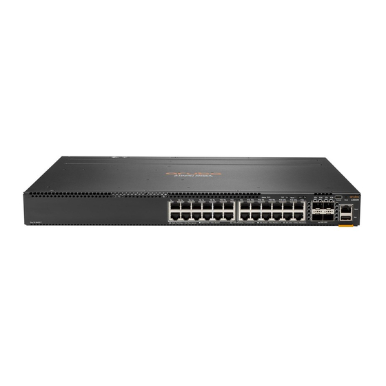
JL668A Aruba 6300F 24G 4SFP56 Swch Related publications Start Here: Installation, Safety, and Regulatory Information for the Aruba 6300F/M Switches and Accessories Start Here: Installation, Safety, and Regulatory Information for the Aruba Modular Power Supplies Start Here: Installation, Safety, and Regulatory Information for the Aruba DC Modular Power Supplies... -
Page 6: Introducing The Switches
Power supplies and power connectors Fan tray and replaceable power supplies (modular switches) Switch features Front of the switches Figure 1 Front of all the 6300 Switches Aruba 6300F/M Switch Series Installation and Getting Started Guide | (xxxx Switch Series) - Page 7 Table 1: Front of all the 6300 switches: Label and description Label Description JL658A Aruba 6300M 24G 24SFP+ 4SFP56 JL659A Aruba 6300M 48SR5 CL6 PoE 4SFP56 JL660A Aruba 6300M 24SR5 CL6 PoE 4SFP56 JL661A Aruba 6300M 48G CL4 PoE 4SFP56 JL662A Aruba 6300M 24G CL4 PoE 4SFP56...
- Page 8 Label Description JL663A Aruba 6300M 48G 4SFP56 and JL762A Aruba 6300M 48G Pwr2Prt 2F 1PS Bdl JL664A Aruba 6300M 24G 4SFP56 JL665A Aruba 6300F 48G CL4 PoE 4SFP56 JL666A Aruba 6300F 24G CL4 PoE 4SFP56 JL667A Aruba 6300F 48G 4SFP56...
-
Page 9: Network Ports
JL667 JL668 JL762 For supported transceivers, see the latest version of the Transceiver Guide on the Aruba Support Portal. Management ports Console port There is a single serial console port on the switch, using a USB Type-C connector. This port is used to connect a console to the switch. -
Page 10: Switch And Port Leds On Front Of The Switches
Slow Flash - Amber One or more ports experiencing PoE failure. PoE mode not selected. On - Amber One or more ports experiencing PoE failure. PoE mode selected. Aruba 6300F/M Switch Series Installation and Getting Started Guide | (xxxx Switch Series) - Page 11 Switch LEDs Function State Meaning Spd LED Indicates Port LEDs are Speed mode not selected showing speed information On - Green Speed mode selected Not Implemented No fault defined Stk LED Indicates Port LEDs are Stacking mode not selected showing stacking mode information On - Green Stacking mode selected...
-
Page 12: Led Mode Select Button And Indicator Leds
A networked out-of-band connection through the management port allows you to manage data network switches from a physically and logically separate management network. For more information, see the Fundamentals Guide for your switch, found on the Aruba Support Portal. Aruba 6300F/M Switch Series Installation and Getting Started Guide | (xxxx Switch Series) -
Page 13: Back Of The Switches
Back of the switches Figure 1 Back of the 6300M Switch Table 7: Back of the 6300 Switch: Label and Description Label Description Fan tray 1 & 2 Power supply slot 1 & 2 Fan requirements Switches Fan Tray 1 Fan Tray 2 JL658A Required... -
Page 14: Power Supplies
This power supply does not provide any PoE power and is keyed so that it will not fit into the power supply slots of Aruba PoE switches. JL760A is for use only in the JL762A switch. This is the only power supply available for the JL762A switch. -
Page 15: Power Connector
Aruba switches. Aruba 6300M 1050W 36-72VDC PSU (JL758A): A 1050 watt power supply used for 6300M PoE switches. Offers up to 740 watts of PoE power, and is keyed so that it will not fit into the power supply slots of non-PoE Aruba switches. -
Page 16: Switch Features
IEEE 802.3af/at JL661A Aruba 6300M 24G Class 4 PoE and 4-port SFP56 Switch JL662A Up to 30W Aruba 6300F 48G Class 4 PoE and 4-port SFP56 Switch JL665A Aruba 6300F/M Switch Series Installation and Getting Started Guide | (xxxx Switch Series) - Page 17 Bluetooth dongle and ArubaOS-CX Mobile App: A convenient way to manage or configure your switch using your mobile device. Aruba AirWave: A powerful and easy-to-use network operations system that manages wired and wireless infrastructures. For more information, visit https://www.arubanetworks.com/products/networking/management/airwave.
- Page 18 Aruba Central: Network management software cloud platform. It offers IT organizations a simple, secure, and cost-effective way to manage and monitor Aruba switches and Aruba instant wireless APs. Support for the Spanning Tree Protocol to eliminate network loops.
-
Page 19: Installing The Switch
Aruba 6300M PoE Switches (with AC power supplies) North America 8121-0973 Australia 8121-0857 North America high line 8121-0941 Brazil 8121-1265 South Africa/India 8121-1483 Europe/South Korea 8120-5336 Israel 8121-1009 China 8121-1034 Aruba 6300F/M Switch Series Installation and Getting Started Guide | (xxxx Switch Series) -
Page 20: Installation Procedures For 6300 Switches
Aruba 6300M PoE Switches (with AC power supplies) United Kingdom/Hong 8120-5334 Argentina 8121-1481 Kong/Singapore/Malaysia Switzerland 8120-5339 Chile 8120-8389 Danish 8120-5340 Thailand/Philippines 8121-0671 Japan high line 8120-5338 (JL086A, Taiwan 15A 8121-1511 (JL086A, JL087A) JL087A) Japan low line 8120-5342 (JL086A) Taiwan 10A... -
Page 21: Installation Precautions And Guidelines
40A for PoE switches when using DC power. When powered by a DC power supply, the installation shall provide a readily accessible two-pole disconnect device in the fixed installation. Aruba 6300F/M Switch Series Installation and Getting Started Guide | (xxxx Switch Series) -
Page 22: Prepare The Installation Site
If your installation requires a different power cord than the one supplied with the switch and power supply, be sure that the cord is adequately sized for the current switch requirements. In addition, be sure to use a power cord displaying the mark of the safety agency that defines the regulations for power cords in your country/region. -
Page 23: Install A Power Supply Or A Second Power Supply For Modular Switches
Figure 2 Air flow Direction of the JL762A Switch Install a power supply or a second power supply for modular switches 1. Remove the power supply blank. Aruba 6300F/M Switch Series Installation and Getting Started Guide | (xxxx Switch Series) - Page 24 2. Insert the power supply. 3. Place the unit inside the rack, making sure the PSU is properly and fully inserted into the switch with the latch locked into place. AC power supply 1. Use the supplied AC cable for the power supply and the 6300M switch being installed. 2.
- Page 25 NOTE: Do not tie the DC cables to the power supply fan handle as it is not designed to take the weight of the cables. Ensure that the DC cable does not obstruct or block the air flow of the power supply fan. Aruba 6300F/M Switch Series Installation and Getting Started Guide | (xxxx Switch Series)
- Page 26 3. Remove the transparent protective cover from the DC input connector of the power supply and set it aside. 4. Install the Ground, +DC, and -DC wires, making sure there is a three-inch gap (1 in below illustration) below the unit for the DC cable. Fasten the Green wire to the Screw Terminal marked with the power supply.
-
Page 27: Verify The Switch Boots Correctly
1. Connect the power cord supplied with the switch to the power connector on the back of the switch. Then plug the power cord into a properly grounded electrical outlet. Aruba 6300F/M Switch Series Installation and Getting Started Guide | (xxxx Switch Series) -
Page 28: Disconnect Power From The Switch
Disconnect the power cord from all of the switch power supplies and from the power sources. Mount the switch After the switch passes self-test, it is ready to be mounted in a stable location. Supported mounting options for the Aruba 6300M switches include: Two-post rack mount Tabletop or desktop Four-post rack mount (Requires the optional J9583A HPE X410 Universal Rack Mounting Kit.) -
Page 29: Mounting The Switch In A Two-Post Rack
To mount the switch in a two-post rack: 1. Attach the rack mount brackets to the switch by using a #1 Phillips (cross-head) screwdriver and the supplied eight 8-mm M4 screws. Aruba 6300F/M Switch Series Installation and Getting Started Guide | (xxxx Switch Series) -
Page 30: Mounting The Switch In A Four-Post Rack
2. Use the four number 12-24 screws to secure the brackets to the rack. Mounting the switch in a four-post rack The four-post rack mount for the switches requires the optional J9583A HPE X410 Universal Rack Mounting Kit. To use this kit to mount a switch, see the installation instructions provided with the kit. Connect the switch to a power source For AC power supplies: Plug the included power cord into the power connector on the switch and into a nearby AC power source. -
Page 31: Connect Network Cables
Connect network cables from network devices or your patch panels to the fixed RJ-45 ports and to any installed transceivers. Connect network cables to the RJ-45 data ports and to any optional transceivers installed on the switch front panel. Aruba 6300F/M Switch Series Installation and Getting Started Guide | (xxxx Switch Series) -
Page 32: Sfp/Sfp+/Sfp28/Sfp56 Installation Notes
Use only an approved Laser Class 1 SFP/SFP+/SFP28/SFP56 transceiver. To ensure proper operation of your switch, use only the HPE Aruba SFP/SFP+/SFP28/SFP56 transceivers supported by your switch. Use only supported Aruba SFP/SFP+/SFP28/SFP56 transceivers Non-Aruba SFP/SFP+/SFP28/SFP56 transceivers are not supported. -
Page 33: Sample Network Topologies
The end node devices are connected to the switch by straight-through or crossover twisted-pair cables. Either cable type can be used because of the IEEE Auto MDI/MDI-X features on the switch. Figure 2 Example as a Segment Switch Aruba 6300F/M Switch Series Installation and Getting Started Guide | (xxxx Switch Series) - Page 34 The switch also works well as a segment switch. That is, with its high performance, it can be used for interconnecting network segments. Simply connect the network hubs that form those segments to the switch or you can also connect other switches. In the preceding illustration, two fast Ethernet hubs with PCs, printers, and local servers attached, are both connected to a switch.
- Page 35 Depending on your bandwidth needs, the links between switches can run at 1G/10G/25G/50G, and use copper or fiber cabling with the appropriate SFP/SFP+/SFP28/SFP56 transceivers. Links can also be aggregated for additional bandwidth and redundancy. Aruba 6300F/M Switch Series Installation and Getting Started Guide | (xxxx Switch Series)
-
Page 36: Getting Started With Switch Configuration
Fundamentals Guide for your switch. Setup for initial configuration For initial configuration information, see the Fundamentals Guide for your switch. Aruba 6300F/M Switch Series Installation and Getting Started Guide | (xxxx Switch Series) -
Page 37: Replacing Components
JL762A (Aruba 6300M 48G Pwr2Prt 2F 1PS Bdl) has power-to-port (back-to-front) airflow and requires two JL761A (Aruba 6300M Power-to-Port Fan Tray). Other 6300M fan trays are not supported in the JL762A switch. All other 6300 switches have port-to-power (front-to-back) airflow; JL761A fan trays are not supported in any other 6300M switch other than the JL762A. -
Page 38: Replacing The Power Supply
Supply) LED will flash simultaneously with the switch Fault LED indicating a power supply has failed. JL762A (Aruba 6300M 48G Pwr2Prt 2F 1PS Bdl) has power-to-port (back-to-front) airflow and requires JL760A (Aruba X371 12VDC 250W 100-240VAC Power-to-Port Power Supply). Other 6300M power supplies are not supported in the JL762A switch. - Page 39 Figure 1 Replacing a Failed Power Supply Table 10: Replacing Failed Power Supply: Label and Description Label Description Lock mechanism Handle Aruba 6300F/M Switch Series Installation and Getting Started Guide | (xxxx Switch Series)
- Page 40 3. Insert the new power supply. Slide it in all the way in until the locking mechanism locks. DC power supply 1. Switch off the DC source and remove the DC cable from the DC source. 2. Remove the transparent protective cover from the DC input connector on the DC power supply. Unfasten the DC cable from the DC power supply.
-
Page 41: Troubleshooting
Nonstandard Cables: Nonstandard and incorrectly wired cables may cause network collisions and other network problems, and can seriously impair network performance. A category 5 or greater cable tester is a recommended tool for every network installation. Aruba 6300F/M Switch Series Installation and Getting Started Guide | (xxxx Switch Series) -
Page 42: Diagnosing With The Leds
Check the Port Configuration: A port on your switch may not be operating as expected because it is administratively disabled in the configuration. It may also be placed into a “blocking” state by a protocol operating on the port (dynamic VLANs), or LACP (dynamic trunking). For example, the normal operation of the spanning tree, GVRP, LACP, and other features may put the port in a blocking state. - Page 43 Slow flash - Amber Fan fault UID LED User-configurable LED User define the locator LED : OFF On/Flash (30 min) - User define the blue locator LED: On/Flash Aruba 6300F/M Switch Series Installation and Getting Started Guide | (xxxx Switch Series)
- Page 44 Switch LEDs Function State/Mode Meaning PSU Status Status of power supply On Green Normal Indicator LED No power, PSU has invalid AC or DC input or invalid DC output Slow Flash - Green Power supply has faulted or warning Diagnostic Tips Problem Solution The switch is not plugged into...
- Page 45 For 1000Base-T connections, verify that the network cabling complies with the IEEE 802.3ab standard. Install the cable according to the ANSI/TIA/EIA-568-A-5 specifications. Ensure that Aruba 6300F/M Switch Series Installation and Getting Started Guide | (xxxx Switch Series)
- Page 46 Problem Solution cable testing complies with the stated limitations for Attenuation, Near-End Crosstalk, Far-End Crosstalk, Equal-Level Far-End Crosstalk (ELFEXT), Multiple Disturber ELFEXT, and Return Loss. The cable verification process must include all patch cables from any end devices, including the switch, to any patch panels in the cabling path.
-
Page 47: Proactive Networking
If you believe the switch is not operating correctly, you can reset the switch to test its circuitry and operating code. To reset a switch, try any of the following: Aruba 6300F/M Switch Series Installation and Getting Started Guide | (xxxx Switch Series) -
Page 48: Checking The Switch Leds
Unplug and plug in the power cord (power cycling). Press the Reset button on the front of the switch. Reboot the switch via the management console’s command. boot system Power cycling the switch and pressing the Reset button both cause the switch to perform its power-on self test, which almost always will resolve any temporary operational problems. -
Page 49: Restoring The Factory Default Configuration
Downloading new switch software Software updates can be downloaded to the switch through several methods. For more information, see Support and Other Resources. Aruba 6300F/M Switch Series Installation and Getting Started Guide | (xxxx Switch Series) -
Page 50: Specifications
SFP56 Power-to-Port 2 Fan Trays 1 PSU (5.7 kg) Bundle (JL762A) Table 13: Removable Parts Item Weight JL086A Power supply 1.83 lb (0.83 kg) JL087A Power supply 1.94 lb (0.88 kg) Aruba 6300F/M Switch Series Installation and Getting Started Guide | (xxxx Switch Series) -
Page 51: Electrical
10000 feet (3 km) Max 10000 feet (3 km) Max altitude Max non-operating 15000 feet (4.6 km) Max 15000 feet (4.6 km) Max altitude Electrical Aruba 6300M PoE Switches (JL659A, JL660A, JL661A, JL662A) Power supply JL670A JL670A AC voltage 110V-120V 200V-240V Maximum current... -
Page 52: Acoustics
50-60 Hz Maximum Power 200W Max 200W Max Acoustics Product* Acoustics JL658A Aruba 6300M 24SFP+ /4SFP56 Swch Sound Power (LWAd) 4.9 Bel Sound Pressure (LpAm) (Bystander) 31.0 dB Aruba 6300F/M Switch Series Installation and Getting Started Guide | (xxxx Switch Series) -
Page 53: Safety
Product* Acoustics JL659A Aruba 6300M 48SR5 CL6 PoE 4SFP56 Swch Sound Power (LWAd) 4.8 Bel Sound Pressure (LpAm) (Bystander) 30.6 dB JL660A Aruba 6300M 24SR5 CL6 PoE 4SFP56 Swch Sound Power (LWAd) 5.2 Bel Sound Pressure (LpAm) (Bystander) 34.2 dB JL661A Aruba 6300M 48G CL4 PoE 4SFP56 Swch Sound Power (LWAd) 4.7 Bel... -
Page 54: Connectivity Standards
Laser Klasse 1 1000-LX IEEE 802.3z 1000BASE-LX EN/IEC Class 1 Laser 60825 Product Laser Klasse 1 1000-LH (not an IEEE standard) EN/IEC Class 1 Laser 60825 Product Aruba 6300F/M Switch Series Installation and Getting Started Guide | (xxxx Switch Series) - Page 55 Laser Safety Information EN/IEC Compatible with these SFP ("mini- Technology Standard SFP+Lasers IEEE standards GBIC") Lasers Compliance Laser Klasse 1 10-Gig (not an IEEE standard) Direct Attach 10-Gig SR IEEE 802.3ae 10GBASE-SR EN/IEC Class 1 Laser 60825 Product Laser Klasse 10-Gig LRM IEEE 802.3aq 10GBASE-LRM EN/IEC...
-
Page 56: Cabling And Technology Information
This section includes switch connector information and network cable information for cables used with the Aruba switches. Incorrectly wired cabling is a common cause of problems for LAN communications. Aruba recommends that you work with a qualified LAN cable installer for assistance with your cabling requirements. - Page 57 Twinaxial copper Direct attach cables One-piece devices consisting of a cable with SFP+ connectors permanently attached to each end, complying with SFF 8431 SFP+ specifications. Multimode fiber 62.5/125 μm or 50/125 μm (core/cladding) diameter, low metal content, graded index fiber-optic cables, complying with the ITU-T G.651 and ISO/IEC 793-2 Type A1b or A1a standards respectively.
-
Page 58: Technology Distance Specifications
Packard Enterprise recommends using Category 6A patch cables. As an alternative, use cable management options to tie down (dress) the Category 6 patch cables so they cannot move. For Conducted and Radiated Immunity in accordance with EN55024, the Aruba switches are limited to Performance Criteria A with shielded cables (CAT6/6A). -
Page 59: Mode Conditioning Patch Cord
Supported Cable Multimode Fibermodal Band- Supported Technology Type width Distances 1000-SX multimode fiber 160 MHz*km 2 - 220 meters 200 MHz*km 2 - 275 meters 400 MHz*km 2 - 500 meters 500 MHz*km 2 - 550 meters 1000-LX multimode fiber 400 MHz*km 2 - 550 meters single mode fiber... -
Page 60: Installing The Patch Cord
Most important, the core diameter of the multimode patch cord must match the core diameter of the multimode cable infrastructure (either 50 or 62.5 microns). Twisted-pair cable/connector pin-outs Auto-MDIX Feature: Aruba 6300F/M Switch Series Installation and Getting Started Guide | (xxxx Switch Series) -
Page 61: Straight-Through Twisted-Pair Cable For 10 Mbps Or 100 Mbps Network Connections
Straight-through twisted-pair cable for 10 Mbps or 100 Mbps network connections Because of the Aruba Auto-MDIX operation of the 10/100 ports on the switch, for all network connections, to PCs, servers or other end nodes, or to hubs or other switches, you can use straight-through cables. -
Page 62: Crossover Twisted-Pair Cable For 10 Mbps Or 100 Mbps Network Connection
If any of these ports are given a fixed configuration, for example 100 Mbps/Full Duplex, the ports operate as MDI-X ports, and crossover cables must be then used for connections to hubs or switches or other MDI-X network devices. Figure 1 Cable Diagram Aruba 6300F/M Switch Series Installation and Getting Started Guide | (xxxx Switch Series) -
Page 63: Straight-Through Twisted-Pair Cable For 1000 Mbps Network Connections
Pins 1 and 2 on connector “A” must be wired as a twisted pair to pins 1 and 2 on connector “B”. Pins 3 and 6 on connector “A” must be wired as a twisted pair to pins 3 and 6 on connector “B”. Pins 4, 5, 7, and 8 are not used in this application, although they may be wired in the cable. - Page 64 Pins 7 and 8 on connector “A” must be wired as a twisted pair to pins 7 and 8 on connector “B”. For 1000Base-T operation, all four pairs of wires are used for both transmit and receive. Aruba 6300F/M Switch Series Installation and Getting Started Guide | (xxxx Switch Series)
-
Page 65: Support And Other Resources
Software licensing https://lms.arubanetworks.com/ End-of-Life information https://www.arubanetworks.com/support-services/end-of-life/ Aruba software and documentation https://asp.arubanetworks.com/downloads Accessing Updates You can access updates from the Aruba Support Portal or the HPE My Networking Website. Aruba 6300F/M Switch Series Installation and Getting Started Guide | (xxxx Switch Series) -
Page 66: Aruba Support Portal
Aruba Support Portal https://asp.arubanetworks.com/downloads If you are unable to find your product in the Aruba Support Portal, you may need to search My Networking, where older networking products can be found: My Networking https://www.hpe.com/networking/support To view and update your entitlements, and to link your contracts and warranties with your profile, go to the Hewlett Packard Enterprise Support Center More Information on Access to Support Materials page: https://support.hpe.com/portal/site/hpsc/aae/home/...
Need help?
Do you have a question about the 6300F Series and is the answer not in the manual?
Questions and answers