
Subscribe to Our Youtube Channel
Related Manuals for Aruba 8400 Series


Summary of Contents for Aruba 8400 Series
- Page 1 Aruba 8400 Switch Series Installation and Getting Started Guide Part Number: 5200-3356 Published: September 2017 Edition: 1...
- Page 2 © Copyright , Hewlett Packard Enterprise Development LP Notices The information contained herein is subject to change without notice. The only warranties for Hewlett Packard Enterprise products and services are set forth in the express warranty statements accompanying such products and services.
-
Page 3: Table Of Contents
Humidity............................Cleanliness............................16 EMI..............................17 Grounding............................. Power............................Cooling............................Space............................Recommended screwdrivers for switch installation................. Shipping a rack-mounted Aruba 8400 Series switch................Chapter 4 Introducing the Aruba 8400 switch series........21 Overview of the Aruba 8400 switch......................Front of the switch............................22 Front chassis LEDs........................ - Page 4 Mounting the chassis in a rack.........................47 Shipping a rack-mounted Aruba 8400 switch chassis..............47 Using a two-post rack mount......................48 Installing the included JL374A Aruba X462 two-post rack mount kit........48 Preparing the chassis for two-post rack mounting............. Manually mounting the chassis in a two-post rack.............
- Page 5 Management module LED behavior....................105 Line module LED behavior......................108 Fabric module LED behavior.......................109 Fan module LED behavior......................110 Rear panel LED behavior......................Aruba Networking tools.......................... Chapter 11 Websites..................113 Chapter 12 Support and other resources...........114 Accessing Hewlett Packard Enterprise Support..................114 Accessing updates..........................Customer self repair..........................115 Remote support............................115...
-
Page 6: Chapter 1 About This Document
Aruba X731 Fan Tray Aruba X731 Fan Tray JL370A Aruba 8400 Fan for X731 Fan Tray Aruba 8400 Fan for X731 Fan Tray JL371A Aruba 8400 1 Fan Tray and 6 Aruba 8400 1 Fan Tray and 6 Fans Bundle... -
Page 7: Related Publications
ArubaOS-CX Diagnostics and Supportability Guide • ArubaOS-CX Introduction to the WebUI Guide For the latest version of this guide or any other Aruba 8400 Switch Series guide, visit http://www.hpe.com/ support/manuals. Switch prompts in examples The switch prompts used in this document are examples and might not match your particular switch or environment. - Page 8 Typically, the switch prompt begins with the host name of the switch. ◦ In addition, when in configuration command contexts, the switch prompt might contain the specific interface name or VLAN ID instead of placeholders such as n or if. Aruba 8400 Switch Series Installation and Getting Started Guide...
-
Page 9: Chapter 2 Installation Precautions And Guidelines
Installation precautions and guidelines Using a mechanical lift to raise, lower, and move the Aruba 8400 chassis is the recommended best practice. If a mechanical lift is used, ensure that the configured weight does not exceed the maximum load capacity of the lift. - Page 10 Mounting a chassis with the front even (flush) with the front of a two-post rack is not supported and can result in a hazardous weight distribution in the rack. See Preparing the chassis for two- post rack mounting on page 49. Aruba 8400 Switch Series Installation and Getting Started Guide...
-
Page 11: Chapter 2 Installation Precautions And Guidelines
Store uninstalled modules in antistatic bags. • Do not ship the Aruba 8400 Series switch mounted in a rack without first checking for rack requirements and restrictions. Otherwise, damage to the switch or components may occur. Damage resulting from using unsupported methods or equipment to ship a rack-mounted chassis may void the switch warranty. - Page 12 • The Aruba 8400 Switch Series chassis and accessories do not include any user-serviceable parts. For service, please contact your authorized Aruba representative. Aruba 8400 Switch Series Installation and Getting Started Guide...
-
Page 13: Chapter 3 Site Preparation
Chapter 3 Site preparation Safety recommendations Before installing an Aruba 8400 Switch, and to avoid possible bodily injury and equipment damage, carefully read these publications before installation: • Safety, Compliance, and Warranty Information (shipped with the switch) • The Aruba 8400 Switch Series Initial Hardware Setup and Safety/Regulatory Guide (shipped with the switch) •... -
Page 14: Preventing Electrostatic Discharge Damage
Remove all power supplies, line modules, two fan trays, and all external cables, including the power cords, before moving the chassis. • Use a minimum of four people to manually move the chassis. Aruba recommends moving the chassis using a mechanical lift, if available. •... -
Page 15: Laser Safety
• Use a portable field service kit with a folding static-dissipating work mat. If you do not have any of the suggested equipment for proper grounding, have an Aruba authorized reseller install the part. For more information on static electricity or assistance with product installation, contact an Aruba authorized reseller. -
Page 16: Humidity
0°C to 40°C (32°F to 104°F) Storage temperature –40°C to +70°C (–40°F to +158°F) For more environmental information, see the latest version of the Aruba 8400 Switch Series Initial Hardware Setup and Safety/Regulatory Guide at http://www.hpe.com/support/manuals. Humidity Maintain the humidity in your equipment room in the acceptable range, as described below. -
Page 17: Emi
Reliably ground the switch to protect it from hazards such as lightning shocks, interferences, and ESD discharges. The switch is grounded through the safety wire in the power cords. Aruba recommends an independent grounding connection for the chassis if there is any doubt about the reliability of the grounding through the power mains. -
Page 18: Power
3. Verify that the power system at the installation site meets the requirements of the power supplies, including the input method and rated input voltage. (For power supply unit information, see the latest version of the Aruba 8400 Switch Series Power Supply Installation and Safety/Regulatory Guide at http://www.hpe.com/support/ manuals.) -
Page 19: Space
( 1 1 . 8 in 3 0 c m ( 1 1 . 8 in 3 0 c m Space For easy installation and maintenance, make sure the rack has enough space to accommodate the switch. For dimensions, see Product dimensions on page 117. Recommended screwdrivers for switch installation Recommended screwdrivers for switch installation •... -
Page 20: Shipping A Rack-Mounted Aruba 8400 Series Switch
Shipping a rack-mounted Aruba 8400 Series switch Do not ship an Aruba 8400 Series switch in a rack without first checking for rack requirements and restrictions. See Shipping a rack-mounted Aruba 8400 switch chassis on page 47. Aruba 8400 Switch Series Installation and Getting Started Guide... -
Page 21: Chapter 4 Introducing The Aruba 8400 Switch Series
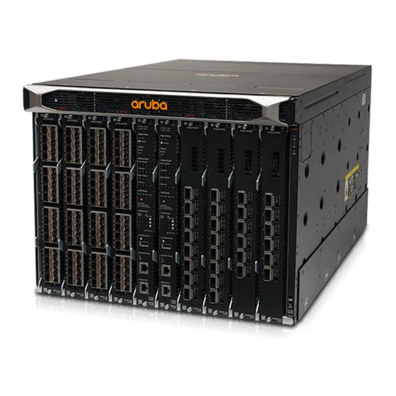
Introducing the Aruba 8400 switch series The Aruba 8400 switch is a campus aggregation and core L2/L3 Ethernet switch. It offers a flexible and innovative approach to deal with the new application, security, and scalability demands of the mobile-cloud and Internet of Things (IoT). -
Page 22: Front Of The Switch
See Appendix A, Specifications on page 117 for more information. Switch configurations The Aruba 8400 switch is available for order as a base bundle with an option to add management modules, fabric modules, and line modules. The following table lists the options available:... -
Page 23: Front Chassis Leds
The following figure indicates the location of the slots and modules on the switch. Figure 1: Aruba 8400: front of the switch Aruba 8400X Aruba 8400X Aruba 8400X Aruba 8400X Aruba 8400 32P SFP+ Adv 32P SFP+ Adv 8P QSFP+ Adv... -
Page 24: Power Supply Unit (Psu) Slots
Chassis health LED Unit identification (UID) Power supply unit (PSU) slots The Aruba 8400 has four power supply unit slots that support the Aruba X382 54DC 2700W AC power supply unit (PSU). Figure 3: Aruba X382 54DC 2700W AC Power Supply (JL372A) - Page 25 6P QSFP28 Adv 8P QSFP+ Adv 32P SFP+ Adv 32P SFP+ Adv JL 363A JL 363A JL 365A JL 366A JL 368A JL 368A JL 366A JL 365A JL 363A JL 363A PSU bezel Chapter 4 Introducing the Aruba 8400 switch series...
-
Page 26: Management Module (Mm) Slots
Management module (MM) slots The Aruba 8400 switch has two management module (MM) slots. These slots are numbered as "5" and "6". Management modules support control plane activities and in-memory running of the Time Series Database. -
Page 27: Space
LED is off after the switch is successfully booted. Indicates the status of the chassis temperature. If the Chassis temperature status (Temp) temperature is at or below the specified rating, then the LED glows steady green, Table Continued Chapter 4 Introducing the Aruba 8400 switch series... - Page 28 With a USB device installed, this LED displays the following after power-on and self-test: • Steady green: USB installed, initialized, and mounted, but no data transfer. • Flicker green: Data transfer in progress USB Micro-B console port Table Continued Aruba 8400 Switch Series Installation and Getting Started Guide...
- Page 29 4. Chassis control functions: The MM can access and control all local peripherals through the PCIe or low-speed control bus. Management module LEDs Each management module has the following LEDs to indicate the status of the MM: Chapter 4 Introducing the Aruba 8400 switch series...
-
Page 30: Line Module (Lm) Slots
3x fan status LEDs (indicate status of the six fans in each fan tray). See http://www.hpe.com/support/networking for more information. Line module (LM) slots The Aruba 8400 switch has eight line module (LM) slots. Figure 7: Line module slots Aruba 8400X... - Page 31 Part# Description JL363A Aruba 8400X 32-port 10GbE SFP/SFP+ with MACsec Advanced Module JL365A Aruba 8400X 8-port 40GbE QSFP+ Advanced Module JL366A Aruba 8400X 6-port 40GbE/100GbE QSFP28 Advanced Module Line module specifications LM variant/Attribute JL363A JL365A JL366A Maximum Bandwidth 320G 320G...
-
Page 32: Rear Of The Switch
The rear of the switch includes: • Four AC power receptacles • Three fan trays with six fan modules each • Three fabric module slots • Rear LED display • Grounding lug Aruba 8400 Switch Series Installation and Getting Started Guide... -
Page 33: Fan Tray And Fan Modules
Rear LED display panel Fan tray and fan modules The Aruba 8400 switch has three fan trays housing six fan modules each. A total of 18 fan modules are housed in the chassis. Chapter 4 Introducing the Aruba 8400 switch series... -
Page 34: Space
Fan tray slot 3 (Shown with fan tray and fan modules installed) • Each fan tray houses six fan modules. • Fan trays are hot swappable. Fan module Figure 11: Fan module Aruba 8400 Switch Series Installation and Getting Started Guide... -
Page 35: Fabric Module (Fm) Slot
Fabric module (FM) slot The Aruba 8400 switch fabric modules and fan trays share the three slots in the rear of the switch. The fabric modules operate on an active mode and data traffic is load balanced between them. They are designed for nonstop serviceability. -
Page 36: Applicable Products
See Applicable products on page 6 for more information. Transceivers See the latest version of the Aruba transceivers guide at http://www.hpe.com/support/manuals Switch software features For information on the Aruba 8400 Switch Series software features, visit http://www.hpe.com/support/manuals Aruba 8400 Switch Series Installation and Getting Started Guide... -
Page 37: Chapter 5 Unpacking, Lifting, And Moving The Chassis
Unpacking the switch components Prerequisites Identify the components received with your Aruba 8400 Switch Series chassis. Some components may ship separate from the pallet on which you received your 8400 Series chassis. Procedure 1. Open the top of the carton. - Page 38 Management module slot cover Front panel bezel Fan tray with six fan modules installed Fabric module Cable manager Line module Management module Two-post rack mount kit Lifting handles (4) ESD wrist strap Aruba 8400 Switch Series Installation and Getting Started Guide...
-
Page 39: Power Cord Information
Attaching an ESD wrist strap Aruba provides an ESD wrist strap with the switch. To minimize ESD damage to electronic components, wear the ESD wrist strap and make sure it is reliably grounded when handling, installing, or removing switch components. -
Page 40: Removing Installed Components From The Chassis
A fully populated Aruba 8400 switch weighs up to 118 kg (260 lbs). If you are manually moving the switch, or if the configured weight exceeds the lift capacity, then use the steps in this section to reduce the weight of the switch for safe manual moves. -
Page 41: Remove Any Installed Line Modules
Fan tray slot 3 (Shown with fan tray and fan modules installed.) Procedure Handle your Aruba 8400 switch fan trays and fan modules with care. Rough or careless handling can damage these components and result in unplanned down time. 1. Select a fan tray to remove. -
Page 42: Move The Chassis To The Mounting Location
Insert the lifting handle hooks into the sockets on the bottom edge of the chassis. Use the guide labels provided for each handle position to orient the handle for attachment. Aruba 8400 Switch Series Installation and Getting Started Guide... -
Page 43: Space
Initial handle position label Locked handle position label b. Slide the handle toward the chassis front until the handle latch engages and the front edge of the handle lines up with the "Lock" label. 4. Using four people, carefully lift the chassis and move it to the mounting location. The rear handles bear more of the chassis weight than the front handles. -
Page 44: Using A Mechanical Lift To Move The Chassis
Using a mechanical lift to move the chassis Prerequisites A fully populated Aruba 8400 switch weighs up to 118 kg (260 lbs). Ensure that the combined weight of the chassis with all components installed does not exceed the maximum load capacity of your mechanical lift. -
Page 45: Chapter 6 Mounting The Chassis
Never place equipment on top of the Aruba 8400 chassis. • Never place the Aruba 8400 chassis on a surface that cannot support the weight of a fully populated chassis, which is 118 kg (260 lbs). Chapter 6 Mounting the chassis... -
Page 46: Manually Positioning The Chassis On A Non-Rack Mount Surface
5. Slide the chassis onto the mounting surface until the front lifting handles are 2.5 cm (1in) from the edge of the mounting surface. 6. Remove the front lifting handles from the chassis. Aruba 8400 Switch Series Installation and Getting Started Guide... -
Page 47: Using A Mechanical Lift To Position The Chassis On A Non Rack Mount Surface
Product dimensions on page 117. Shipping a rack-mounted Aruba 8400 switch chassis Aruba supports shipping of rack-mounted Aruba 8400 switches where the rack or cabinet is: • A Hewlett Packard Enterprise four-post rack product compatible with the JL373A 4-post rack rail kit. -
Page 48: Using A Two-Post Rack Mount
• Hewlett Packard Standard Series racks Shipping an Aruba 8400 switch chassis in a two-post rack is not supported and may result in damage to the switch or components. The Aruba warranty does not apply to products damaged or rendered defective as a result of using non supported shipping methods. -
Page 49: Preparing The Chassis For Two-Post Rack Mounting
Procedure 1. Attach the two large mounting brackets to the rear of the posts, with the flanges facing inward. 2. Attach the two small brackets to the front of the posts with the flanges facing inward. 3. Use the flathead screws to secure the ends of the cross bar to the outside surface of the large brackets. (The cross bar keeps the large mounting brackets at the proper width for the chassis.) Preparing the chassis for two-post rack mounting Prerequisites... -
Page 50: Manually Mounting The Chassis In A Two-Post Rack
Manually mounting the chassis in a two-post rack Prerequisites • The JL374A Aruba X462 two-post Rack Rail Kit is installed on your two-post rack. • The rack ears included in the JL374A kit are mounted on the switch. (See Preparing the chassis for two- post rack mounting on page 49.) -
Page 51: Space
Procedure 1. With four people lifting on the included four lifting handles, raise the switch to the level of the rack mount bracket. 2. Slide the switch into the rack until the rack bracket supports the rear of the chassis. 3. -
Page 52: Using A Mechanical Lift To Mount The Chassis In A 2-Post Rack
Using a mechanical lift to mount the chassis in a 2-post rack A fully populated Aruba 8400 chassis weighs up to 118 kg (260 lbs). Ensure that the combined weight of the chassis with all components installed does not exceed the maximum load capacity of your mechanical lift. -
Page 53: Installing The Optional Jl373A Aruba X464 4-Post Rack Rail Kit
Installing the optional JL373A Aruba X464 4-post Rack Rail Kit Adjustable slide rail (left side) Adjustable slide rail (right side) Rear shipping brackets Shipping support plates Rack mount ears Flathead and 10-32 Screws Cage nuts Prerequisites • Ensure that the four-post rack or cabinet you plan to use is rated to support the weight of all devices you plan to install in the rack or cabinet. -
Page 54: Space
Mount devices installed in a rack or cabinet as low as possible. Mount the heaviest devices at the bottom of the rack and lighter devices higher up. 2. Secure both rails to the front and back posts with the included 10-32 screws. Aruba 8400 Switch Series Installation and Getting Started Guide... -
Page 55: Space
Rail secured to front post Rail secured to rear post 3. Insert four included cage nuts into the appropriate positions on both of the front posts. The cage nuts must be spaced to receive the screws that attach the chassis rack ears to the front posts after the chassis has been mounted in the rack. -
Page 56: Space
Rack rails installed in the four-post rack you are using to mount the chassis. (See Installing rack rails and rack ears on page 54.) Procedure 1. Use the included flat-head screws to attach the shipping support plates to each side of the rear of the chassis. Aruba 8400 Switch Series Installation and Getting Started Guide... -
Page 57: Space
2. Insert four included cage nuts in the appropriate positions on both rear posts. The cage nuts must be spaced to receive the screws that attach the rear shipping brackets to the rear posts. Use an unattached rear shipping bracket as a guide for placing the cage nuts. Unattached rear shipping bracket used as a guide for cage nut placement. -
Page 58: Manually Mounting The Chassis In A Four-Post Rack
The four lift handles shipped with the switch chassis are installed on the chassis. (See Manually moving the chassis on page 42.) • The equipment rack is prepared to receive the chassis. See Installing the optional JL373A Aruba X464 4- post Rack Rail Kit on page 53. •... -
Page 59: Space
4. Continue sliding the chassis onto the rails until they fully support the chassis weight. 5. Remove the two front lifting handles. 6. Slide the chassis into the rack until the rack ears contact the rack posts. 7. Use the screws provided in the accessory kit for the rack ears to secure the chassis to the rack. Before attempting to configure or use the switch, be sure to secure it to the rack using the screws and rack mounting ears provided. -
Page 60: Using A Mechanical Lift To Mount The Chassis In A Four-Post Rack
56.) A fully populated Aruba 8400 chassis weighs up to 118 kg (260 lbs). Ensure that the combined weight of the chassis with all components installed does not exceed the maximum load capacity of your mechanical lift. -
Page 61: Grounding The Chassis
The switch is grounded through the safety wire in the power cords. If there is any doubt about the reliability of the grounding through the power mains, Aruba recommends an independent grounding connection for the chassis. Note the location of the grounding lug. - Page 62 1. Remove the grounding lug and two screws from the rear of the switch. 2. Crimp the grounding lug to a properly grounded 6 AWG stranded grounding cable. 3. Securely reattach the grounding lug to the switch with the two screws. Aruba 8400 Switch Series Installation and Getting Started Guide...
-
Page 63: Chapter 7 Installing Components
Hold management modules, line modules, and fabric modules by their edges. Do not touch any electronic components or printed circuitry. • Store uninstalled modules in antistatic bags. Handle your Aruba 8400 Switch components with care. Rough or careless handling can damage the components and result in unplanned down time. Chapter 7 Installing components... -
Page 64: Installing A New Power Supply Unit In An Empty Slot
Power supply slot 2 and slot cover Power supply slot 3 and slot cover Power supply slot 4 and slot cover 2. Remove the slot cover from a power supply slot and store it for future use. Aruba 8400 Switch Series Installation and Getting Started Guide... - Page 65 3. Slide the power supply unit half way into the open power supply slot. 4. Grasp the power supply handle and slide the unit into the slot until it clicks into place. The front of the power supply unit must be firmly seated, with the front of the unit flush with the front of the chassis. 5.
- Page 66 105 to verify power supply operation. The 8400 Series chassis and PSUs do not include a power on/off switch. PSUs are powered on by connecting the AC power cord to the chassis and to an AC power source.
-
Page 67: Install Management Modules In Slots 5 And 6
Skip this task if your management module(s) are already installed. Procedure Handle your Aruba 8400 switch management modules with care. Rough or careless handling can damage the modules and result in unplanned down time. 1. Put on an ESD wrist strap and properly ground it on the switch. See Attaching an ESD wrist strap on page 2. -
Page 68: Install Up To Eight Line Modules
Install up to eight line modules Procedure Handle your Aruba 8400 switch line modules with care. Rough or careless handling can damage the modules and result in unplanned down time. 1. Put on an ESD wrist strap and properly ground it to the chassis. See Attaching an ESD wrist strap on page 2. -
Page 69: Grounding
To prevent particles from entering unused transceiver ports, keep dust plugs in any ports where a transceiver is not installed. For information on Aruba optical transceivers and cable assemblies supported on your Aruba 8400 Series Switch, see the latest version of the Aruba Transceiver Guide at http://www.hpe.com/support/manuals. -
Page 70: Installing Fabric Modules If Not Already Installed
For more information on line rate support, see Fabric module line rate support on page 118. Handle your Aruba 8400 switch fabric modules with care. Rough or careless handling can damage the modules and result in unplanned downtime. -
Page 71: Installing A Fan Tray In Any Empty Fan Tray Slot
Individual JL370A fan modules are included in the JL371A Aruba 8400 1 Fan Tray and 6 Fans Bundle shipped from the factory. To replace (or install) a JL370A fan module in a JL369A Fan Tray, see Installing or replacing a fan module on page 99. -
Page 72: Installing The Cable Manager
Fan tray slot 3 (with fan tray installed). For proper cooling and ventilation, a powered-up 8400 Series chassis must have all three fan trays installed and all fan modules in each fan tray running. Do not remove a fan tray from a powered up switch without having a fully populated replacement fan tray available. -
Page 73: Installing The Cable Manager In A Two-Post Rack
Install the switch in a two-post or four-post rack, as described in Mounting the chassis on page 45. • Install one or more Aruba 8400 switch line modules. • Install transceivers in the line modules. (See the ArubaOS-Switch Transceiver Guide at http://www.hpe.com/ support/manuals.) -
Page 74: Attaching The Touch Fasteners To The Cable Manager Blocks
A cable manager block has two posts, with two fastener positions on each post. Prerequisites • The switch is mounted in a two-post or four-post rack. • The cable manager is installed. Aruba 8400 Switch Series Installation and Getting Started Guide... -
Page 75: Attaching The Cable Manager Blocks To The Cable Manager Mount
Procedure 1. Form a loop in a fastener by threading the fastener end through the slot in the fastener. 2. Slide the fastener into a fastener position on one of the posts and tighten. 3. Curl the fastener back onto itself to prevent tangling with other fasteners. 4. -
Page 76: Space
A hole is provided in the cable manager block to allow a long Torx T-15 driver access to the release screw on the bottom of the cable manager block. The module and cable manager block can be removed without disturbing adjacent cable manager blocks. Aruba 8400 Switch Series Installation and Getting Started Guide... -
Page 77: Chapter 8 Activating The Switch
1. Plug the supplied power cords into the AC inlets on the rear panel of the chassis and tighten the retainer screws. The Aruba 8400 Series switches do not have a power switch. They are powered on when the power cord is connected to the switch and to a power source. -
Page 78: Chassis Leds Indicating Normal Operation
Chassis LEDs indicating normal operation After NOS boot-up Chassis power LED Steady green Chassis health LED Steady green Unit identification (UID) Management module LEDs, reset button, and physical ports Management module LEDs Aruba 8400 Switch Series Installation and Getting Started Guide... - Page 79 After NOS boot-up Management module health LED Steady green The switch is ready; finished booting from the Network Operating System (NOS). Mgmt state Active state (Actv) Steady green Off if not the active (Actv) management module. Standby state (Stby) Steady green Off if not the standby (Stby) management module.
- Page 80 Fabric module status (1) (2) (3) Steady green Fan tray status (1) (2) (3) Steady green Fans (fan modules 1 - 6 in indicated fan tray.) Steady green Management module reset button and physical ports Aruba 8400 Switch Series Installation and Getting Started Guide...
- Page 81 Reset Button and Ports After NOS boot-up Mgmt Reset button. Recessed button used to reset the selected management module. For operation, see Functions of the management module reset button on page 102. Auxiliary port Without a USB device installed, this LED is off after power-on and self- test.
-
Page 82: Line Module Port Leds
Flickering half-bright to full-bright green: Varying port activity level. ◦ Steady green: Port at high utilization • Spd in LED Mode options lighted: ◦ Steady green: Port linked at maximum speed ◦ Flashing green: Port linked below maximum speed Aruba 8400 Switch Series Installation and Getting Started Guide... -
Page 83: Rear Panel Leds
Rear panel LEDs After NOS boot-up Power supply status (1) (2) (3) Steady green for each installed PSU Unit identification (UID) Chassis power LED Steady green Chassis health LED Steady green Chassis temperature status Steady green: Temperature at or below rating (Temp) Fabric modules Steady green per fabric module... -
Page 84: Where To Go From Here
Connect an RJ-45 to DB9 console cable to the RJ-45 console port and to a computer running terminal emulation software. You can order an optional JL448A Aruba X2 C2 RJ45 to DB9 console cable by contacting your Aruba sales representative. -
Page 85: Chapter 9 Adding Or Replacing Switch Components
Aruba recommends using the CLI to shut down modules before removing them from the switch. This provides a controlled shutdown process that minimizes traffic loss and loss of function. However it also can cause a longer delay in getting the replacement module operational. -
Page 86: Using Controlled Shut Down To Add Or Replace Line Modules
1. Put on a snugly fitting ESD wrist strap and attach it to the ESD connector on the front of the switch. (See Attaching an ESD wrist strap on page 39.) 2. Use this command to deactivate the slot: switch(config)# module <SLOT-ID> admin-state down Aruba 8400 Switch Series Installation and Getting Started Guide... -
Page 87: Replacing A Line Module With Another Of A Different Type
The existing slot configuration remains. 3. Remove the module from the slot and place it in an anti-static bag. 4. Install the new module. 5. Use this command to re-activate the slot. switch(config)# module <SLOT-ID> admin-state up The module then comes up using the existing slot configuration. 6. -
Page 88: Using Controlled Shutdown To Add Or Replace Fabric Modules
Using controlled shutdown to add or replace fabric modules For proper cooling and ventilation, a powered-up 8400 Series chassis must have all three fan trays installed and all fan modules in each fan tray running. Do not remove a fan tray from a powered up switch without having a fully populated replacement fan tray available. -
Page 89: Space
Procedure Removing or replacing the standby management module: 1. Put on an ESD wrist strap and connect it to the ESD connection point on the front of the chassis. (See Attaching an ESD wrist strap on page 39.) 2. Identify the standby Management module. The Stby LED and the corresponding Mgmt Modules slot number (5 or 6) show a solid green. -
Page 90: Removing Or Replacing An Active Management Module
3. Using the CLI, execute the redundancy-switchover command to convert the Active management module to Standby, and the Standby management module to Active. Switch(config)# redundancy-switchover Switch(config)# For more information on module commands, see the ArubaOS-CX Command Reference Guide at http:// www.hpe.com/support/manuals. Aruba 8400 Switch Series Installation and Getting Started Guide... -
Page 91: Removing Or Replacing A Fabric Module
After using the redundancy-switchover command, check the Active, Standby, and Mgmt LEDs on both modules to ensure that the Active/Standby conversion took place. If the Standby management module was not available when the command was executed, the conversion fails. 4. Loosen the screws securing the module you converted to Standby in step 3. 5. - Page 92 Remove only one fan tray at a time. Removing more than one fan tray at a time shuts down the switch. For proper cooling and ventilation, a powered-up 8400 Series chassis must have all three fan trays installed and all fan modules in each fan tray running. When installing or removing a fabric module in a running switch, replace the fan tray within 5 minutes of removing it.
-
Page 93: Removing A Fabric Module
Removing a fabric module Prerequisites • Identify the switch member number and fan tray slot number for the slot containing the fabric module to be removed. • Remove the fan tray from the slot containing the fabric module to remove. See Removing a fan tray before installing or replacing a fabric module on page 91. -
Page 94: Installing The Replacement Fabric Module
2. Grasp the two fabric module handles between your thumb and index finger and gently squeeze the tab release triggers. 3. Swing the hinged handles outward. 4. Slide the module into the slot until it stops. 5. Rotate the hinged handles inward until they latch into place. Aruba 8400 Switch Series Installation and Getting Started Guide... -
Page 95: Space
6. Insert the fan tray into the slot. 7. Tighten the four screws securing the fan tray in the slot. 8. Access the global configuration context in the switch CLI (switch(config)#) 9. Execute the fabric <SLOT-NUM> admin-state up command to activate the Fabric module. Then use the show run command to verify that the fabric module is activated. -
Page 96: Removing Or Replacing A Line Module
6. If you do not plan to install another line module in the empty slot, then secure a line module slot cover over the slot opening. 7. To install another line module in the empty slot: , Aruba 8400 Switch Series Installation and Getting Started Guide... -
Page 97: Replacing A Fan Tray
Six JL370A fan modules are included in the JL371A Aruba 8400 1 Fan Tray and 6 Fans Bundle shipped from the factory. To replace (or install) an individual JL370A fan module in a JL369A Fan Tray, see Installing or replacing a fan module on page 99. -
Page 98: Removing The Fan Tray
2. Loosen the four retaining screws securing the fan tray to the chassis. 3. Using the two vertical fan tray handles, grasp and slide the fan tray out of the fan tray slot. Aruba 8400 Switch Series Installation and Getting Started Guide... -
Page 99: Installing The Replacement Fan Tray
You can install or replace a fan module while the switch is either running or powered down. Prerequisites Have a JL370A fan module (Aruba 8400 Fan for X731 Fan Tray) ready to install in a fan tray. Procedure 1. If you are installing a fan module in an empty slot, skip to step 3. -
Page 100: Space
Depress the tab on the top of the module. c. Slide the fan module firmly into the slot and release the tab. d. Check the fan module LED to ensure the module is operating properly. Aruba 8400 Switch Series Installation and Getting Started Guide... -
Page 101: Chapter 10 Troubleshooting
• Store uninstalled modules in antistatic bags. Handle your Aruba 8400 Switch components with care. Rough or careless handling can damage the components and result in unplanned down time. Basic troubleshooting tips The following situations cause most problems. Check for these items first when starting your troubleshooting:... -
Page 102: Functions Of The Management Module Reset Button
Use a new, correctly wired cable. For pinouts and correctly wired cable, compare your cable to the cable information in the latest version of the Aruba Transceiver Guide at http://www.hpe.com/support/manuals. A category 5 cable tester is a recommended tool for every 1000Base-T network installation. -
Page 103: Diagnosing With Leds
Module Soft reset: Press Reset button for less Hard reset: Press Reset button for five than five seconds seconds or more Module "A" • Resets management module "A" after a • Immediately resets management Active 5-10 second delay for orderly shutdown. module "A". -
Page 104: Chassis Led Behavior
Slow Flash Green Booting Slow Flash Orange Fault condition somewhere in the system Chassis UID (unique identifier) LED LED state Meaning Not activated On Blue Location aid Slow Flash Blue Location aid Aruba 8400 Switch Series Installation and Getting Started Guide... -
Page 105: Power Supply Led Behavior
Power supply LED behavior Power supply LEDs Power LED Fault LED Power supply condition state state On Green Normal operation No AC power to power supply Flashing AC power is present, but the power supply is not supplying power to the Green chassis On Green... - Page 106 Fault condition Fast Flash Orange Hardware (ASIC) mismatch Table 9: Management Modules: 5-6 LED state Meaning Not present or module is shut down and ready for removal On Green Operating normally Aruba 8400 Switch Series Installation and Getting Started Guide...
- Page 107 Status Rear LEDs Table 10: Fabric Modules: 1-3 LED state Meaning Powered down, ready for removal On Green Normal operation Slow Flash Green Booting or initializing Slow Flash Orange Fault condition Fast Flash Orange Hardware (ASIC) mismatch Table 11: Fan Trays: 1-3 LED state Meaning On Green...
-
Page 108: Line Module Led Behavior
Fault condition Fast Flash Orange Hardware (ASIC) mismatch Line module port LEDs when LED mode is Link/Activity LED behavior for port LEDs is set by LED Mode button on management module. Aruba 8400 Switch Series Installation and Getting Started Guide... -
Page 109: Fabric Module Led Behavior
LED State Meaning Port is disabled, not connected or not receiving a link indication from the connected device Half-Bright Green Port is enabled and receiving a link indication from the connected device Switching between Half-Bright and Port is actively transferring data Full-Bright Green On Green Port is at high utilization... -
Page 110: Fan Module Led Behavior
Slow Flash Green Booting Slow Flash Orange Fault condition somewhere in the system Chassis Unique Identifier (UID) LED LED state Meaning Not activated On Blue Location aid Slow Flash Blue Location aid Aruba 8400 Switch Series Installation and Getting Started Guide... -
Page 111: Aruba Networking Tools
Operating normally Slow Flash Orange Fan is in a fault condition or is not present Aruba Networking tools • A graphical web browser interface you can use to manage your switch from a PC running a supported web browser. For more information, see the ArubaOS-CX Fundamentals Guide at http://www.hpe.com/support/ manuals. -
Page 112: Space
To apply IMC or other network management tools to your Aruba 8400 switch, first enable SNMP, which is disabled in the default configuration. To enable SNMP, see the latest version of the ArubaOS-CX Fundamentals Guide at http://www.hpe.com/support/manuals. Aruba 8400 Switch Series Installation and Getting Started Guide... -
Page 113: Chapter 11 Websites
Chapter 11 Websites Networking Websites Hewlett Packard Enterprise Networking Information Library www.hpe.com/networking/resourcefinder Hewlett Packard Enterprise Networking Software www.hpe.com/networking/software Hewlett Packard Enterprise Networking website www.hpe.com/info/networking Hewlett Packard Enterprise My Networking website www.hpe.com/networking/support Hewlett Packard Enterprise My Networking Portal www.hpe.com/networking/mynetworking Hewlett Packard Enterprise Networking Warranty www.hpe.com/networking/warranty General websites Hewlett Packard Enterprise Information Library... -
Page 114: Chapter 12 Support And Other Resources
To view and update your entitlements, and to link your contracts and warranties with your profile, go to the Hewlett Packard Enterprise Support Center More Information on Access to Support Materials page: www.hpe.com/support/AccessToSupportMaterials Aruba 8400 Switch Series Installation and Getting Started Guide... -
Page 115: Customer Self Repair
Access to some updates might require product entitlement when accessed through the Hewlett Packard Enterprise Support Center. You must have an HPE Passport set up with relevant entitlements. Customer self repair Hewlett Packard Enterprise customer self repair (CSR) programs allow you to repair your product. If a CSR part needs to be replaced, it will be shipped directly to you so that you can install it at your convenience. -
Page 116: Regulatory Information
For online help content, include the product name, product version, help edition, and publication date located on the legal notices page. Aruba 8400 Switch Series Installation and Getting Started Guide... -
Page 117: Specifications
Appendix A Specifications Specifications Product weights Use the values in the following table to determine the weight of the switch with any mix of installed components. Chassis or Weight Loading factors component Fully loaded chassis Up to 118 kg (260 lbs) Empty chassis 36.5 kg (80.5 lbs) without blank slot covers 40.1 kg (88.4 lbs) with all blank slot covers... -
Page 118: Fabric Module Line Rate Support
8x40GbE line modules (only; one or redundancy . more in any mix) JL366A 6x40GbE line modules at Supported at approximately 75-80% of line rate on all ports. 100GbE (one or more) Table Continued Aruba 8400 Switch Series Installation and Getting Started Guide... -
Page 119: System Power Consumption
600W Fans Bundle The Aruba 8400 switch is designed to operate with three fully populated fan trays (18 fan modules) installed, regardless of the component loading on the switch. Assumes three fully populated fan trays. Total power consumption for all three fully populated fan trays is 600W. - Page 120 • At low-line, two PSUs (which can source up to 2565W). • At high line, one PSU (which can source up to 2700W). More power supplies are required for redundancy. Aruba 8400 Switch Series Installation and Getting Started Guide...
-
Page 121: Ordering Additional Accessory Parts
5066-3090 DB9 to RJ45 1.5m console cable DB9 to RJ45 1.5 meter console cable See also Applicable products on page 6. To order additional Aruba 8400 Switch Series parts, contact your authorized Aruba dealer. Appendix B Ordering additional accessory parts...
Need help?
Do you have a question about the 8400 Series and is the answer not in the manual?
Questions and answers