Table of Contents
Advertisement
Advertisement
Table of Contents

Subscribe to Our Youtube Channel
Related Manuals for Aruba Instant On 1430


Summary of Contents for Aruba Instant On 1430
- Page 1 Aruba Instant On 1430 Installation and Getting Started Guide...
- Page 2 Copyright Information © Copyright 2022 Hewlett Packard Enterprise Development LP. Open Source Code This product includes code licensed under the GNU General Public License, the GNU Lesser General Public License, and/or certain other open source licenses. A complete machine-readable copy of the source code corresponding to such code is available upon request.
-
Page 3: Table Of Contents
Contents Contents Contents About this Document Applicable Products Related Publications Overview Switch Hardware Features Switch Features Site Preparation and Switch Installation Precautions Safety Recommendations Installation Precautions and Guidelines Prepare the Installation Site Installation Overview Included Parts Installation Procedure Troubleshooting Troubleshooting Overview Basic Troubleshooting Tips Specifications Environmental Specifications... -
Page 4: About This Document
(R8R48A) Aruba Instant On 1430 24G Switch (R8R49A) Aruba Instant On 1430 26G 2SFP Switch (R8R50A) All other Aruba Instant On 1430 switches operate with internal power supplies. Related Publications Aruba Instant On 1430 Switch Series Quick Setup Guide and Safety/Regulatory Information To access the above publications, visit https://community.arubainstanton.com/. -
Page 5: Overview
Overview Overview The Aruba Instant On 1430 Switch series are designed to meet the needs of small business network environments - simple to setup and manage, secure and reliable. These switches are intended for indoor use only. The switches comply with the safety standard IEC 60950-1, 2nd Edition and IEC 62368-1 2nd Edition. - Page 6 Figure 3 R8R45A Figure 4 R8R45A rear Item Description 1GbE RJ45 ports Link/Status LED per port Global Status LED 8 x 1GbE RJ45 Ports Figure 5 R8R46A front Overview |...
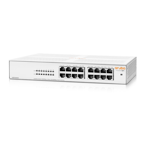
- Page 7 Figure 6 R8R46A rear Item Description 1GbE RJ45 ports Link/Status LED per port Global Status LED PoE Max LED PoE Status LED per port 8 x 1GbE RJ45 & PoE ports Figure 7 R8R47A Item Description PoE & 1GbE RJ45 ports Link/Status LED per port PoE Status LED per port 16 x 1GbE RJ45 &...
- Page 8 Figure 8 R8R48A Item Description 1GbE RJ45 ports Link/Status LED per port 16 x 1GbE RJ45 ports Global Status LED Figure 9 R8R49A Item Description 1GbE RJ45 ports Link/Status LED per port 24 x 1GbE RJ45 ports Global Status LED Overview |...
- Page 9 Figure 10 R8R50A Item Description 1GbE RJ45 ports Link/Status LED per port 26 x 1GbE RJ45 ports 2 x 1GbE SFP ports with Link/Status LED per port Global Status LED Network Ports Auto-sensing 10/100/1000BASE-T ports: These ports have the “Auto-MDIX” feature, which means that you can use either straight-through or crossover twisted-pair cables to connect any network devices to the switch.
- Page 10 124W Switch (R8R48A) Ethernet Alliance PoE Certified Certified Aruba PoE power sourcing equipment (PSE) has been verified for IEEE 802.3™ PoE interoperability by passing the Ethernet Alliance (Gen 1 or Gen 2) PoE Certified program test plan, minimizing interoperability issues between PoE products.
- Page 11 Switches powered on when connected to an active AC power source Aruba Instant On 1430 16G Switch (R8R47A) Aruba Instant On 1430 24G 16G Class4 PoE 124W Switch (R8R48A) Aruba Instant On 1430 24G Switch (R8R49A) Aruba Instant On 1430 26G 2SFP Switch (R8R50A) These switches automatically adjust to any voltage between 100-127 and 200-240 volts and either 50 or 60 Hz.
-
Page 12: Switch Features
Aruba Instant On 1430 5G Switch (R8R44A) Aruba Instant On 1430 8G Switch (R8R45A) Aruba Instant On 1430 8G Class4 PoE 64W Switch (R8R46A) The external AC/DC power adapter supplies 12 volts DC to the R8R44A and R8R45A switches and automatically adjusts to any AC voltage between 100-240 volts and either 50 or 60 Hz. -
Page 13: Site Preparation And Switch Installation Precautions
Note, however, that the preferred position for the fanless Aruba Instant On 1430 switches is at the base of the rack or cabinet (for optimal cooling) or below as many of the other products as can be accommodated. - Page 14 Only Aruba-approved power cords may be used with Aruba devices. To access power cord information for your switch, see Included Parts. Lost or damaged power cords must be replaced only with Aruba- approved power cords. If your installation requires a different power cord than the one supplied with the switch and/or power supply, be sure that the cord is adequately sized for the current requirements of the switch.
-
Page 15: Prepare The Installation Site
Prepare the Installation Site Make sure the physical environment into which you will be installing the switch is properly prepared, including having the correct network cabling ready to connect to the switch and having an appropriate location for the switch. Verify that copper and fiber cabling meets the requirements of the Cabling and Technology Information Specifications. -
Page 16: Installation Overview
Aruba Instant On 1430 Start Here: Installation, Safety, and Regulatory Information Aruba Instant On 1430 Quick Card Additional safety and regulatory information For the latest version of documentation for your switch model, visit the Aruba Instant On Support site at https://community.arubainstanton.com/. Software License, Warranty, and Support information Power cord and/or AC/DC power adapter, depending on the switch model. -
Page 17: Installation Procedure
R8R47A and R8R48A Kit number 5300-1807 4 rubber feet 2 wall/table mounting screws rack screws 1 tie strap 5555 R8R49A Kit number 5300-1808 4 rubber feet 2 wall/table mounting screws rack screws 1 tie strap R8R50A Kit number 5300-1809 4 rubber feet 2 wall/table mounting screws rack screws 1 tie strap... - Page 18 Use only Aruba transceivers in 1430 switches. Using any other transceivers is done at your own risk and may void support and warranty. 1. Prepare the Installation Site If you have not already done so, carefully read Site Preparation and Switch Installation Precautions.
- Page 19 Rack or Cabinet Mounting All switches, except the Aruba Instant On 1430 5G Switch (R8R44A) and Aruba Instant On 1430 8G Switch (R8R45A), can be mounted in a rack. The switches are designed to be mounted in any EIA-standard 19-inch Telco rack or communication equipment cabinet.
- Page 20 For safe operation, please read Installation Precautions and Guidelines before mounting the switch. For rack mounting, do not physically stack equipment on top of another. Ensure an air gap of at least 3 inches. The screws supplied with the switch are the correct threading for standard EIA/TIA open 19-inch racks. If you are installing the switch in an equipment cabinet such as a server cabinet, use the clips and screws that came with the cabinet in place of the screws that are supplied with the switch.
- Page 21 the bracket holes, then insert and tighten the four 12-24 screws holding the brackets to the rack. Wall Mounting You can mount all switches on a wall with either the front or rear panel facing up. For safe operation, please read Installation Precautions and Guidelines before mounting the switch.
- Page 22 Installation and Getting Started | Installation and Getting Started Guide...
- Page 23 To mount the 5- and 8-port switches, follow these steps: 1. In the required location, mark the position for the mounting screws. Refer to the diagrams below for the ports-down mounting hole locations of R8R44A, R8R45A, and R8R46A. Figure 11 R8R44A Figure 12 R8R45A Figure 13 R8R46A Installation Overview |...
- Page 24 2. Use a #1 Phillips (cross-head) screwdriver and attach the mounting brackets to the switch with the included 8-mm M4 screws. Wall anchors are included in the accessory kit for use with plastered brick or concrete walls. A third 20-mm M4 tap screw can be placed against one surface of the switch to secure it. Under-Table Mounting All switches can be mounted beneath a table.
- Page 25 Nothing should be placed on top of the switch, nor should additional units be stacked above. Adequate spacing on all sides needs to be maintained for ventilation. 4. Connect the Switch to a Power Source Procedure 1. Connect the power cord supplied with the switch to the power connector on the back of the switch, and then into a properly grounded electrical outlet, as shown in the Verify the Switch Passes Self Test section.
- Page 26 Remove the protective plastic cover and retain it for later use. Hold the SFP by its sides and gently insert it into any of the slots on the switch until the SFP clicks into place. The Aruba SFPs are Class 1 laser devices. Avoid direct eye exposure to the beam coming from the transmit port.
- Page 27 Use only an approved Laser Class 1 SFP transceiver. To ensure proper operation of your switch, use only the Aruba SFP transceivers supported by your switch. Use only supported Aruba SFP transceivers. Non-Aruba SFP transceivers are not supported. Use of supported Aruba products ensures that your network maintains optimal performance and reliability.
- Page 28 SFP Connections to Devices with Fixed Speed When connecting a device to your switch port that contains an SFP transceiver, the speed and duplex settings of the switch port and the connected device must match. If the settings do not match, the device may not link properly—you may not get a link. For some older network devices, the default speed/duplex settings may be predefined.
-
Page 29: Troubleshooting
Chapter 5 Troubleshooting Troubleshooting Troubleshooting Overview This section describes how to troubleshoot the switch. For more information, see Aruba Instant On 1430 5G/8G/16G/24G/26G Switch Series Management and Configuration Guide. This chapter describes the following: basic troubleshooting tips – Basic Troubleshooting Tips diagnosing with the LEDs –... - Page 30 If the power source and power cord are OK and this condition persists, the switch power supply may have failed. Call your Aruba authorized network reseller, or use the electronic support services from Aruba to get assistance. ➋ The network port for Try power cycling the switch.
- Page 31 1. Check in the table for the LED pattern you see on your switch. 2. Refer to the corresponding diagnostic tip. LED Pattern Indicating Problems Diagnostic Tips (see table below) PoE Max Port Link Port PoE ➊ On solid (orange) ➋ Slow flash (orange) Slow flash (green) ➌...
-
Page 32: Specifications
Aruba Instant On 1430 8G Switch (R8R45A) 5.35 x 6.16 x 1.46 in 1.27 lbs (0.57 kg) 5.74 x 6.95 x 1.46 in Aruba Instant On 1430 8G Class4 PoE 64W Switch 1.71 lbs (0.77 kg) (R8R46A) Aruba Instant On 1430 16G Switch (R8R47A) 10.00 x 10.79 x 1.73 in... -
Page 33: Standards
Aruba Instant On 1430 5G Switch (R8R44A) Power/Pressure: 0 dB (no fan) Power/Pressure: 0 dB (no fan) Aruba Instant On 1430 8G Switch (R8R45A) Aruba Instant On 1430 8G Class4 PoE 64W Switch Power/Pressure: 0 dB (no fan) (R8R46A) Aruba Instant On 1430 16G Switch (R8R47A) - Page 34 Cable Type OperationMode Description Multimode fiber 62.5/125 μm or 50/125 μm (core/cladding) diameter, low metal content, graded index fiber-optic cables, complying with theITU-T G.651 and ISO/IEC 793-2 Type A1b or A1a standards respectively.* Single mode 9/125 μm (core/cladding) diameter, low metal content fiber-optic fiber cables, complying with the ITU-T G.652 and ISO/IEC 793-2 Type B1 standards.
-
Page 35: Support Information
Chapter 7 Support Information Support Information Main Instant On site https://www.arubainstanton.com/ Support https://support.arubainstanton.com/ Instant On social forums and knowledge base https://community.arubainstanton.com/ Security bulletins https://www.arubanetworks.com/support-services/security-bulletins/ End-user license agreement https://www.arubainstanton.com/eula/ Support contact numbers https://www.arubainstanton.com/contact-support/ Installation and Getting Started | Installation and Getting Started Guide...
Need help?
Do you have a question about the Instant On 1430 and is the answer not in the manual?
Questions and answers