
Related Manuals for Aruba CX 10000 Series


Summary of Contents for Aruba CX 10000 Series
- Page 1 Aruba CX 10000 Distributed Services Switch Installation and Getting Started Guide Published: December 2021 Edition: 1...
- Page 2 Copyright Information © Copyright 2022 Hewlett Packard Enterprise Development LP. Open Source Code This product includes code licensed under the GNU General Public License, the GNU Lesser General Public License, and/or certain other open source licenses. A complete machine-readable copy of the source code corresponding to such code is available upon request.
-
Page 3: Table Of Contents
Four-Post Rack Mount Option Install Transceivers Connect the Switch to a Power Source Setup for Initial Configuration Connect Network Cables Using RJ-45 Out-of-band Management Port Connecting Cables to Transceivers Aruba CX 10000 Distributed Services Switch | Installation and Getting Started Guide... - Page 4 Power Consumption Environmental Specifications Acoustics Safety and Regulatory Information Connectivity Standards Cabling and Technology Information Cabling Specifications Technology Distance Specifications Support and Other Resources Accessing Aruba Support Accessing Updates Aruba Support Portal My Networking Warranty Information Regulatory Information Documentation Feedback Contents...
-
Page 5: About This Document
Applicable products Aruba CX 10000-48Y6C Distributed Services Front-to-Back 6 Fans 2 Power Supplies Bundle (R8P13A) Aruba CX 10000-48Y6C Distributed Services Back-to-Front 6 Fans 2 Power Supplies Bundle (R8P14A) Aruba CX 10000-48Y6C Port to Power (FB) AC Power Supply Unit (R8R51A) -
Page 6: Introducing The Switches
Switch features Overview The Aruba CX 10000 Distributed Services Switch is a new category of switches, ideally suited for enterprise data centers. The Aruba CX 10000 combines best-of-breed Aruba data center L2/L3 switching with the industry's first hardware-accelerated programmable processor (Pensando DSM), delivering stateful software-defined services inline with orders of magnitude scale and performance improvements over traditional data center switches. -
Page 7: Network Ports
Console port Aruba 10000 switches include an RJ-45 serial console port on the front of the switch. This port is used to connect a console to the switch by using an RJ-45 serial cable (not supplied). A DB9-to-RJ-45 console cable can be ordered from HPE: JL448A, Aruba X2C2 RJ45 to DB9 Console Cable. -
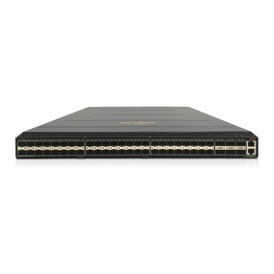
Page 8: Chassis And Port Leds On The Front Of The Switch
The USB-A port is used for file management, downloading switch software or use of Aruba accessories. This port uses a USB Type-A connector. Chassis and port LEDs on the front of the switch Figure 2 Chassis and Port LEDs for the Aruba Aruba CX 10000-48Y6C Distributed Services switch... - Page 9 Switch LEDs Function LED State Meaning Behavior Normal No valid link Solid Green Valid link indication Fault No fault FLASH Amber (Blinks Fault synchronously with Global Status LED.) Displays Link Startup No valid link (AOS-CX and Out-Of-Band- information for the SVOS.) Management OOBM port.
-
Page 10: Switch Product Label
Global Status LED.) Switch product label The switch product label is an Aruba Orange-colored tab on the bottom right side of the switch front panel. Pull the tab out to view the product label information. The product label information includes the part number, model number, serial number, and MAC address. -
Page 11: Back Of The Switch
Health and UID (locator) LEDs Power supplies The Aruba 10000 switch does not have a power switch; it is powered on when at least one installed power supply is connected to an active AC power source. The power supplies automatically adjust to any voltage between 100-127 and 200-240 volts and either 50 or 60 Hz. -
Page 12: Power Supply Information
Release Latch Pull Handle The Aruba 10000 switch is shipped with two hot-swappable, field-replaceable, AC power supplies. Each power supply has a country-specific power cord for connection to an AC power outlet. The switch can operate with one active power supply. -
Page 13: Load Sharing
Redundancy With power redundancy, the Aruba 10000 switch can continue normal operation even when one power supply fails or is powered off. When two power supplies are installed, if one becomes unavailable (fails, is powered off or removed) the remaining power supply provides full power for the device. - Page 14 Red release latch indicates Port-to-Power airflow. Blue release latch indicates Power-to-Port airflow. Fan tray Color code Aruba CX 10000-48Y6C Port to Power(FB) Fan (R8R53A) Aruba CX 10000-48Y6C Power to Port(BF) Fan Blue (R8R54A) Aruba CX 10000 Distributed Services Switch | Installation and Getting Started Guide...
-
Page 15: Fan Tray Status Led
If multiple Fan trays have failed, the switch will power off and reboot in 5 minutes to reassess cooling capabilities. The Aruba 10000 switch is not compatible with fan trays from other Aruba hardware platforms. Fan tray status LED Fan tray LED... - Page 16 Support for many advanced features to enhance network performance: For a description, see the OS-CX guides for your switch. Ability to update the switch software. To download product updates, go to the Aruba Support Portal. Aruba CX 10000 Distributed Services Switch | Installation and Getting Started Guide...
-
Page 17: Installing The Switch
USB Bluetooth adapter: Enables you to configure your switch from a mobile device. Requires the Aruba CX Mobile App. For information about using the Aruba CX mobile app to configure the switch, see the Fundamentals Guide for your switch and software release. -
Page 18: Parts Not Included
Parts not included If you have not already done so, order an Aruba rack mount kit for use with your 10000 switch. Rack mounting your Aruba 10000 switch is supported using these rack mount kits: Aruba CX 10000 1U 4 post Rack Mount Kit (R8R56A) A DB9-to-RJ-45 console cable can be ordered from HPE: JL448A, Aruba X2C2 RJ45 to DB9 Console Cable. -
Page 19: Grounding The Switch
This equipment is intended to be grounded to comply with emission and immunity requirements. Ensure that the switch functional ground lug is connected to earth ground during normal use. Aruba CX 10000 Distributed Services Switch | Installation and Getting Started Guide... - Page 20 To make sure that the equipment is reliably connectd to earth ground, follow the grounding procedure instructions and use a UL-listed ring terminal lug suitable for 10-to-8 AWG wire. Use at least a 10 AWG (5.26 mm2) conductor to connect to the external grounding screw. To ground the switch: 1.
-
Page 21: Prepare The Installation Site
In the back of the switch, leave a minimum of 6 inches (15.24 cm) of space for the power cord. Cooling air flow in Aruba 10000 switches is Port-to-Power or Power-to-Port, depending on which power supply and fan tray options are installed. To reverse the cooling air flow direction in an 10000 switch, you must replace the existing power supplies and fan trays with power supplies and fan trays having the opposite air flow direction. -
Page 22: Install Fan Trays
Figure 7 Installing a power supply Install fan trays Skip this step if all six fan tray slots are already populated with fan trays. Use the following steps to install a fan tray in any empty fan tray slot. Ensure that a replacement fan has the same airflow as other fan trays installed in the switch (Port-to-Power or Power-to-Port). -
Page 23: Power-On The Switch And Check Leds
Power-on the switch and check LEDs Prerequisites The Aruba 10000 switch does not contain a power on/off switch. It is turned on by connecting the AC power cord to the switch and an AC power source. Check LEDs for proper switch operation. For further detail see... -
Page 24: Two-Post Rack Mount Option
Two-post Rack Mount Option The switch is designed to be mounted in any EIA-standard 19-inch telco rack or communication equipment cabinet using the Aruba X412 1U Universal 2-Post Rack Mount Kit (R8R55A; sold separately). For safe operation, please review the mounting precautions in... - Page 25 2. Hold the switch with attached brackets up to the rack and move it vertically until rack holes line up with the bracket holes, then insert and tighten the four number 12-24 screws, attaching the brackets to the rack. Aruba CX 10000 Distributed Services Switch | Installation and Getting Started Guide...
-
Page 26: Four-Post Rack Mount Option
Figure 11 Mounting the switch in a two-post rack (Center-of-Gravity position) Four-Post Rack Mount Option The Aruba 10000 switch can be mounted in four-post racks and cabinets by using the Aruba CX 10000 1U 4 post Rack Mount Kit (R8R56A); sold separately. - Page 27 3. Insert the rack mount and chassis into the rack, making sure to align the rail mount tips to the mechanical B2F and F2F ears. 4. Attach the included 10-32 Torx head screws and tighten them using the T20 to 13 in-lbs wrench. Aruba CX 10000 Distributed Services Switch | Installation and Getting Started Guide...
- Page 28 Figure 14 Mounting the switch in a four-post rack (front-to-back) Figure 15 Mounting the switch in a four-post rack (back-to-front) 5. Secure the rack mount to the rack ears on each side using three M3 T20 Panhead screws and tighten them with the T20 to 13 in-lbs wrench.
-
Page 29: Install Transceivers
Hold the transceiver by its sides and gently insert it into the switch until it clicks into place. When a transceiver is inserted, the switch authenticates it. This can take 1-3 seconds, with the worst case being 5 seconds. Aruba CX 10000 Distributed Services Switch | Installation and Getting Started Guide... - Page 30 The Aruba transceivers are Class 1 laser devices. Avoid direct eye exposure to the beam coming from the transmit port. The transceivers operate only at full duplex. Half duplex operation is not supported. Use of supported genuine Aruba transceivers is always recommended. Non-Aruba SFP28/QSFP+/QSFP28 transceivers are not supported.
-
Page 31: Connect The Switch To A Power Source
Using the Aruba CX mobile app: The Aruba CX mobile app can connect to the switch through the USB Bluetooth adapter. For information about using the Aruba CX mobile app to configure the switch, see the Fundamentals Guide for your switch and software release. -
Page 32: Using Rj-45 Out-Of-Band Management Port
Connect the network cables from the network devices or your patch panels to the RJ-45 out-of-band management port on the switch or to any transceivers you have installed in the switch. See Prepare the installation site for further detail. Using RJ-45 Out-of-band Management Port If you plan to manage the switch from a dedicated management network, connect an RJ-45 network cable from the management network to the Mgmt port. -
Page 33: Initial Configuration With An Out-Of-Band Serial Connection
For more detailed information, refer to the switch software manuals for your switch. Console Cable Pinout The Aruba X2C2 RJ45 to DB9 Console Cable (JL448A) has an RJ-45 plug on one end and a DB-9 female connector on the other end. RJ-45 to DB-9 pinouts... - Page 34 DB-9 (Signal reference from RJ-45 (Signal reference from chassis) > Reserved Reserved Reserved Reserved Initial Configuration with an Out-of-Band Serial Connection...
-
Page 35: Replacing Components
1. Remove the AC power cable from the power supply’s connector. 2. Grasping the handle of the failed power supply, use the Release Latch to release the locking mechanism. Aruba CX 10000 Distributed Services Switch | Installation and Getting Started Guide... -
Page 36: Replacing A Fan Tray
The Fan LED will FLASH amber, indicating a fan tray has failed. The Aruba 10000 switch is not compatible with fan trays from other Aruba hardware platforms. After removing a fan tray, wait at least five seconds before inserting a replacement fan tray in the same slot. - Page 37 4. Insert the new fan tray fully into the slot so that its face plate is flush with the back face of the switch and the latch clicks. If the switch is connected to an AC power source, the fan tray should immediately start running. Figure 19 Replacing a fan tray Aruba CX 10000 Distributed Services Switch | Installation and Getting Started Guide...
- Page 38 Label Description Fan tray release latch Fan tray handle Replacing Components...
-
Page 39: Troubleshooting
By default, ports do not run selftest at boot. To enable port selftest on boot, save the no fastboot configuration to the switch. See AOS-CX software documentation for further detail. Diagnosing with the LEDs LED Patterns for General Switch Troubleshooting Aruba CX 10000 Distributed Services Switch | Installation and Getting Started Guide... -
Page 40: Diagnostic Tips
If the power source and power cord are OK and this condition persists, the switch power supply may have failed. Call your Aruba authorized network reseller, or use the electronic support services from Aruba to get assistance. Try power cycling the PSU or removing and re-inserting the PSU. - Page 41 For example, if the switch port is configured as “Full-duplex”, the port on the attached device also MUST be configured as “Full-duplex”. If the configurations don’t match, the Aruba CX 10000 Distributed Services Switch | Installation and Getting Started Guide...
-
Page 42: Hardware Diagnostic Tests
Problem Solution results could be a very unreliable connection, or no link at all. Run an internal selftest on the port. For example, to run a selftest on port 1/1/12: diagnostics diagnostics loopback 1/1/12 If the command reports fail, contact Support. There may be a hardware fault. -
Page 43: Checking Console Messages
Remplacer uniquement avec une batterie du même type ou d'un type équivalent recommandé par le constructeur.Mettre au rebut les batteries usagées conformément aux instructions du fabricant. Aruba CX 10000 Distributed Services Switch | Installation and Getting Started Guide... - Page 44 The only indicator of battery failure is the failure of the switch internal clock to keep the correct time across a reboot or power cycle. If a battery failure occurs, contact your authorized Aruba representative for assistance. Batteries are not customer-serviceable and battery failures should be referred only to service personnel authorized by Aruba.
-
Page 45: Physical
(R8P14A) Supply Power Cords Aruba includes the power cord intended for use with your Aruba switch and power supply. Different countries/regions may require different power cords. For a list of the power cords that apply to your switch, Included parts. -
Page 46: Power Consumption
Only Aruba-approved power cords may be used with Aruba devices. To access power cord information for your switch, see Included parts. Lost or damaged power cords must be replaced only with Aruba-approved power cords. If your installation requires a different power cord than the one supplied with the switch and/or power supply, be sure that the cord is adequately sized for the current requirements of the switch. -
Page 47: Acoustics
1:2014 & 2018 Safety-Worldwide IEC 60950-1:2005+A1:2009+A2:2013; IEC 62368-1:2014 & 2018 North American CSA/CUS 62368-1:2014 Lasers EN60825-1:2014 / IEC 60825-1: 2014 Class 1 Class 1 Laser Products / Laser Klasse 1 Aruba CX 10000 Distributed Services Switch | Installation and Getting Started Guide... -
Page 48: Connectivity Standards
EN 55024:2010+A2016/CISPR24:2015 EN 55032:2015/CISPR32 Class A EN55035:2017/CISPR35 EN 61000-3-2:2019, Class A EN 61000-3-3:2013 FCC CFR 47 Part 15:2010 Class A ICES-003 Class A VCCI Class A CNS 13438 Class A RoHS EN 63000:2018 When selecting a fiber SFP or QSFP device, make sure the device has the same (or better) operating temperature range as the switch. - Page 49 EN/IEC 60825 Class 1 Laser Product Laser Klasse 1 100-Gig LR4 IEEE 802.3ba 100GBASE-LR4 EN/IEC 60825 Class 1 Laser Product Laser Klasse 1 100-Gig DAC IEEE 802.3bj 100GBASE-CR4 Aruba CX 10000 Distributed Services Switch | Installation and Getting Started Guide...
- Page 50 Compatible with these EN/IEC standard com- Technology Lasers IEEE standards pliance 40-Gig DAC IEEE 802.3ba 40GBASE-CR4 25-Gig SR IEEE 802.3by 25GBASE-SR EN/IEC 60825 Class 1 Laser Product Laser Klasse 1 25-Gig eSR (not an IEEE standard) EN/IEC 60825 Class 1 Laser Product Laser Klasse 1 25-Gig LR...
-
Page 51: Cabling And Technology Information
This chapter includes switch connector information and network cable information for cables that should be used with Aruba CX 10000 Distributed Services switches. Incorrectly wired cabling is a common cause of problems for LAN communications. Aruba recommends that you work with a qualified LAN cable installer for assistance with your cabling requirements. -
Page 52: Technology Distance Specifications
For 10GBASE-T, Category 6 patch cables are sensitive to movement once link has been established, and could cause link to drop if moved. Therefore, Aruba recommends using Category 6A patch cables, or using cable management options to tie down (dress) the Category 6 patch cables so they cannot move. - Page 53 1500 MHz*km 2 - 100 meters 3500 MHz*km 2 - 150 meters 40GBASE-eSR4 multimode fiber 1500 MHz*km 2 - 330 meters 3500 MHz*km 2 - 550 meters Aruba CX 10000 Distributed Services Switch | Installation and Getting Started Guide...
- Page 54 Supported cable Multimode fibermodal Technology Supported distances type bandwidth 40GBASE-LR4 single mode fiber 2 - 10,000 meters 40GBASE-ER4 single mode fiber 2 - 40,000 meters 40GBASE-BiDi multimode fiber 1500 MHz*km 2 - 100 meters 3500 MHz*km 2 - 150 meters 100GBASE-CR4 twinaxial copper (various lengths offered)
-
Page 55: Support And Other Resources
End-of-Life information https://www.arubanetworks.com/support-services/end-of-life/ Aruba software and documentation https://asp.arubanetworks.com/downloads Accessing Updates You can access updates from the Aruba Support Portal or the HPE My Networking Website. Aruba Support Portal Aruba CX 10000 Distributed Services Switch | Installation and Getting Started Guide... -
Page 56: My Networking
If you are unable to find your product in the Aruba Support Portal, you may need to search My Networking, where older networking products can be found: My Networking https://www.hpe.com/networking/support To view and update your entitlements, and to link your contracts and warranties with your profile, go to the Hewlett Packard Enterprise Support Center More Information on Access to Support Materials page: https://support.hpe.com/portal/site/hpsc/aae/home/...
Need help?
Do you have a question about the CX 10000 Series and is the answer not in the manual?
Questions and answers