Table of Contents
Advertisement
Advertisement
Table of Contents

Related Manuals for Aruba S1500 Series


Summary of Contents for Aruba S1500 Series
- Page 1 Aruba S1500 Series Mobility Access Switch...
- Page 2 Legal Notice The use of Aruba Networks, Inc. switching platforms and software, by all individuals or corporations, to terminate other vendors’ VPN client devices constitutes complete acceptance of liability by that individual or corporation for this action and indemnifies, in full, Aruba Networks, Inc.
-
Page 3: Table Of Contents
Connecting and Disconnecting the AC Power Cord ...........30 Connecting the AC Power Cord..............31 Installing an SFP....................31 Removing an SFP ..................31 Connecting an LC Fiber Optic Cable ............32 Disconnecting an LC Fiber Optic Cable............32 Specifications, Safety, and Compliance..........33 Aruba S1500 Series Mobility Access Switch | Installation Guide... - Page 4 Safety and Regulatory Compliance ..............33 Electromagnetic Interference ................34 Battery Statements ..................35 Proper Disposal of Aruba Equipment ..............35 Waste of Electrical and Electronic Equipment ..........35 European Union RoHS ..................36 China RoHS ....................36 Aruba S1500 Series Mobility Access Switch | Installation Guide...
-
Page 5: Preface
Preface This document describes the hardware features of the Aruba S1500 Series Mobility Access Switch. This document provides a detailed overview of the physical and performance characteristics of each Mobility Access Switch model and explains how to install the Mobility Access Switch and its accessories. -
Page 6: Contacting Support
Wireless Security Incident http://www.arubanetworks.com/support-services/security-bulletins/ Response Team (WSIRT) Support Email Addresses Americas and APAC support@arubanetworks.com EMEA emea_support@arubanetworks.com WSIRT Email wsirt@arubanetworks.com Please email details of any security problem found in an Aruba product. | Preface Aruba S1500 Series Mobility Access Switch | Installation Guide... -
Page 7: S1500 Mobility Access Switch
The S1500 is a multiport Ethernet Mobility Access Switch that offers Layer 2 switching and limited Layer 3 features, and the capability to act as a wired access point. The S1500 series includes three models with different port configurations. Table 2 Aruba S1500 Mobility Access Switch Models... -
Page 8: S1500 Components
12P Quantity 24P or 48P Quantity Aruba Document Pointer (Printed) Small form-factor pluggable (SFP) transceivers are available for use with the Aruba S1500 series and are sold separately. Contact your Aruba sales representative for details and assistance. S1500 Components This section introduces the component and its location in the S1500 series. - Page 9 POWER, STATUS, and STACK LEDs Used for basic monitoring of the S1500 Mobility Access Switch Mode status LEDs LEDs for mode status MODE button Used for toggling the mode status LEDs Uplink ports 4 x 1000BASE-X ports for SFP Aruba S1500 Series Mobility Access Switch | Installation Guide S1500 Mobility Access Switch |...
-
Page 10: Access Ports (Ethernet Ports)
Function Mode Indicator Status LINK/ACT Displays Green (Solid) Link has been established Link status Green (Blinking) Link has been established and activity on link No link | S1500 Mobility Access Switch Aruba S1500 Series Mobility Access Switch | Installation Guide... -
Page 11: Power, Status, And Stack Leds
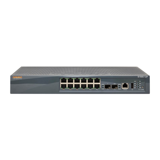
7. In the S1500-24P or S1500-48P model, the POWER, STATUS, and STACK LEDs are aligned vertically, as shown in Figure Figure 7 S1500-12P LEDs and Ports Aruba S1500 Series Mobility Access Switch | Installation Guide S1500 Mobility Access Switch |... -
Page 12: Mode Status Leds And Mode Button
S1500-24P or S1500-48P models, as shown in Figure 8. Push the MODE button to toggle between the modes for the port status. | S1500 Mobility Access Switch Aruba S1500 Series Mobility Access Switch | Installation Guide... -
Page 13: Uplink Ports
1000BASE-X uplink ports, as shown in Figure 7 Figure 8. It is recommended to use Aruba supported SFP transceivers in these ports. Each uplink port has two LEDs. These LEDs are used to monitor the status and activity on each port. -
Page 14: Console Port
CLI, the SHUTDOWN LED turns red when the system halt completely halts. If the temperature of the S1500 exceeds the temperature threshold, the SHUTDOWN LED turns On. | S1500 Mobility Access Switch Aruba S1500 Series Mobility Access Switch | Installation Guide... -
Page 15: Security Slot
The S1500 series support PoE (802.3af) and PoE+ (802.3at) to provide power to connected devices. PoE/ PoE+ is enabled by default to provide plug and play capability for PoE capable devices. The S1500 series has three PoE management modes: Dynamic mode: This is the default mode. -
Page 16: Sfp Modules
Aruba tests and supports Aruba approved optics within their Mobility Access Switch devices. Non-approved third party optics are not tested or supported; therefore, Aruba does not guarantee proper functionality of non-approved third party optics when used in an Aruba system. For a complete list of Aruba approved optics, contact your Aruba sales representative. -
Page 17: Installation
Installation of the device should be performed by a trained installation professional. CAUTION This chapter describes how to install the Aruba S1500 Mobility Access Switch using the mounting options available. The S1500 accessory kit includes the equipment required to install the Mobility Access Switch in a standard, two-point 19-inch telco rack. -
Page 18: Selecting A Location
The following tools and equipment are required for installing an S1500 Mobility Access Switch: Mount Bracket (x2) (included in the kit): Do not use for table or shelf installation | Installation Aruba S1500 Series Mobility Access Switch | Installation Guide... -
Page 19: Installation Steps
2. Secure the bracket to the Mobility Access Switch using the eight screws for rack mount bracket (four per bracket) and a suitable screwdriver. Figure 10 Rack Mount Brackets (S1500-12P) Figure 11 Rack Mount Brackets (S1500-24P or S1500-48P) Aruba S1500 Series Mobility Access Switch | Installation Guide Installation |... - Page 20 Figure 12 for the S1500-12P model Figure 13 for the S1500-24P or S1500-48P model). Figure 12 Rack Mount Installation- Standard (S1500-12P) Figure 13 Rack Mount Installation- Standard (S1500-24P or S1500-48P) | Installation Aruba S1500 Series Mobility Access Switch | Installation Guide...
-
Page 21: Rack Mount Installation- Mid
Screws for rack mount bracket (x8): S1500-12P— M3 x 6.5 mm Phillips Flat Head Screws S1500-24P or S1500-48P— M4 x 8 mm Phillips Flat Head Screws Aruba S1500 Series Mobility Access Switch | Installation Guide Installation |... -
Page 22: Installation Steps
3. Mount the Mobility Access Switch within your organization’s rack system using the four screws for system rack mount (two per bracket) and suitable screwdriver (see Figure 17 for the S1500-12P model Figure 18 for the S1500-24P or S1500-48P model). | Installation Aruba S1500 Series Mobility Access Switch | Installation Guide... - Page 23 Leave a minimum of 10 cm (4 inches) of space on the left and right side of the unit for proper air flow and ventilation. Leave additional space in the front and the back of the unit to access network cables, LED status indicators, and power cord. Aruba S1500 Series Mobility Access Switch | Installation Guide Installation |...
-
Page 24: Wall Mount Installation
For the S1500-24P or S1500-48P model, an optional accessory kit (purchased separately) is available that allows mounting the S1500 Mobility Access Switch on a wall. For more information about the S1500 Mobility Access Switch Wall Mounting Kit, contact your Aruba sales representative. Required Tools and Equipment... - Page 25 4. Align the mounting bracket holes with the holes you created in the wall (see Figure 21 for the S1500-12P model and Figure 22 for the S1500-24P or S1500-48P model). Aruba S1500 Series Mobility Access Switch | Installation Guide Installation |...
- Page 26 Figure 21 Wall Mounting (S1500-12P) | Installation Aruba S1500 Series Mobility Access Switch | Installation Guide...
-
Page 27: Magnet Mount Installation (Only For The S1500-12P Model)
This is an optional accessory kit (purchased separately) that allows mounting the S1500-12P Mobility Access Switch on a ferrous surface. For more information about the S1500-12P Mobility Access Switch Magnet Mounting Kit, contact your Aruba sales representative. Required Tools and Equipment Magnet Bars (x2): 100 mm x 15 mm x 4 mm ... -
Page 28: Installation Steps
S1500-12P Mobility Access Switch. c. Secure the magnets to the chassis using the four screws for magnet mount (two per magnet) and a suitable screwdriver (see Figure 23). | Installation Aruba S1500 Series Mobility Access Switch | Installation Guide... -
Page 29: Required Tools And Equipment
Required Tools and Equipment Rubber Feet (included in this kit) Installation Steps Ensure that the magnet bars is not installed on the bottom of the S1500-12P Mobility Access Switch. Aruba S1500 Series Mobility Access Switch | Installation Guide Installation |... -
Page 30: Connecting And Disconnecting The Ac Power Cord
Mobility Access Switch is not equipped with an On/Off switch. The device will turn On when the AC power cord has been connected to the power supply module and an AC power outlet. | Installation Aruba S1500 Series Mobility Access Switch | Installation Guide... -
Page 31: Connecting The Ac Power Cord
To remove an SFP module from the S1500 Mobility Access Switch: 1. Open and release the latch on the SFP module. 2. Pull and remove the module from the port. Aruba S1500 Series Mobility Access Switch | Installation Guide Installation |... -
Page 32: Connecting An Lc Fiber Optic Cable
3. Slide the cable into place until a connection is made and an audible click is heard. Disconnecting an LC Fiber Optic Cable Depress to release the latch on the cable and simultaneously pull the cable out of the SFP-SX or SFP-LX module. | Installation Aruba S1500 Series Mobility Access Switch | Installation Guide... -
Page 33: Specifications, Safety, And Compliance
The Aruba S1500 Mobility Access Switch must be installed by a professional installer. The professional installer is responsible for ensuring that grounding is available and it meets applicable local and national electrical codes. CAUTION... -
Page 34: Electromagnetic Interference
Cet appareil numérique respecte les limites de bruits radioélectriques applicables aux appareils numériques de Classe A prescrites dans la norme sur le matériel brouilleur: “Appareils Numériques,” NMB-003 édictée par le ministère des Communications. | Specifications, Safety, and Compliance Aruba S1500 Series Mobility Access Switch | Installation Guide... -
Page 35: Battery Statements
Proper Disposal of Aruba Equipment Waste of Electrical and Electronic Equipment Aruba products at end of life are subject to separate collection and treatment in the EU Member States, Norway, and Switzerland and therefore are marked with the symbol shown at the left (crossed-out wheelie bin). The treatment applied at end of life of these... -
Page 36: European Union Rohs
RoHS Directive are Lead (including Solder used in printed circuit assemblies), Cadmium, Mercury, Hexavalent Chromium, and Bromine. Some Aruba products are subject to the exemptions listed in RoHS Directive Annex 7 (Lead in solder used in printed circuit assemblies).
Need help?
Do you have a question about the S1500 Series and is the answer not in the manual?
Questions and answers