
Related Manuals for Aruba 2930M


Summary of Contents for Aruba 2930M
- Page 1 Aruba 2930M Switches Installation and Getting Started Guide Part Number: 5200-5214a Published: November 2018 Edition: 2...
- Page 2 © Copyright 2017 Hewlett Packard Enterprise Development L.P. Notices The information contained herein is subject to change without notice. The only warranties for Hewlett Packard Enterprise products and services are set forth in the express warranty statements accompanying such products and services.
-
Page 3: Table Of Contents
Contents Chapter 1 About this document..............6 Applicable products............................6 Related publications...........................6 Terminology..............................7 Chapter 2 Introducing the 2930M switches........... Front of the switches..........................9 Network ports..........................Management ports........................Console Ports........................13 Auxiliary (Aux) port......................Switch and port LEDs on front of the switches................14 LED mode select button and indicator LEDs................ - Page 4 Testing switch-to-device network communications............... Testing end-to-end network communications................80 Restoring the factory default configuration....................Downloading new switch software......................Chapter 7 Specifications................Switch specifications..........................81 Physical............................81 Electrical............................82 Environmental..........................Acoustics............................84 Safety............................Connectivity standards........................85 Stacking module specifications........................86 Physical............................86 Environmental..........................Uplink port specifications......................... Physical............................87 Aruba 2930M Switches...
- Page 5 Environmental..........................Chapter 8 Cabling and technology information.......... Cabling specifications..........................Technology distance specifications......................90 Mode conditioning patch cord........................Installing the patch cord........................... Twisted-pair cable/connector pin-outs..................... Straight-through twisted-pair cable for 10 Mbps or 100 Mbps network connections.....93 Cable diagram........................assignments......................... Crossover twisted-pair cable for 10 Mbps or 100 Mbps network connection........94 Cable diagram........................
-
Page 6: Chapter 1 About This Document
Related publications • Aruba 2930M Switches Installation and Getting Started Guide • Aruba 2930M and 3810M Switch Power Supply Quick Setup Guide and Safety/Regulatory Information • HPE ArubaOS-Switch software manuals • HPE ArubaOS-Switch Power Over Ethernet (PoE/PoE+) Planning and Implementation Guide •... -
Page 7: Terminology
Terminology In instances where the text refers collectively to both PoE+ and PoE Class 6 in the 2930M switch family, PoE is used to refer to both. Chapter 1 About this document... -
Page 8: Chapter 2 Introducing The 2930M Switches
When 2930M stacking modules are installed in the switches, any combination of up to ten 2930M switches can be stacked together through high-speed backplane cables to form a single extended virtual switch. See Stacking information and topologies and the HPE ArubaOS-Switch Advanced Traffic Management Guide for your switch OS version for more stacking information. -
Page 9: Front Of The Switches
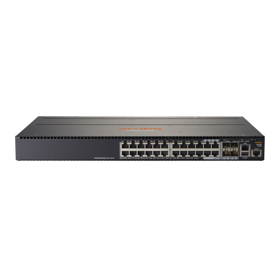
• Switch features Front of the switches Figure 1: Front of all the 2930M switches Table 1: Front of all the 2930M switches: Label and description Label Description Aruba 2930M 24G 1-slot switch (JL319A) Aruba 2930M 24G PoE+ 1-slot switch (JL320A) - Page 10 Description Aruba 2930M 40G 8SR PoE+ 1-slot Switch (JL323A) Aruba 2930M 40G 8 HPE Smart Rate PoE Class 6 1-slot Switch (R0M67A) Aruba 2930M 24SR PoE+ 1-slot Switch (JL324A) Aruba 2930M 24 HPE Smart Rate PoE Class 6 1-slot Switch (R0M68A)
-
Page 11: Network Ports
Aruba 2930M 48G PoE+ 1-slot switch (JL322A): Aruba 2930M 40G 8SR PoE+ 1-slot switch (JL323A): Aruba 2930M 40G 8 HPE Smart Rate PoE Class 6 1-slot switch (R0M67A) Aruba 2930M 24SR PoE+ 1-slot switch (JL324A): Aruba 2930M 24 HPE Smart Rate PoE Class 6 1-slot switch (R0M68A) - Page 12 RJ-45 (twisted-pair) 1000-SX Fiber (multimode) 1000-LX Fiber (multimode or single mode) 1000-LH Fiber (single mode) 1000-BX Fiber (single mode) 10 Gbps 10-Gig Direct Copper Attach (twinaxial) Applicable 10-Gig SR Fiber (multimode) 10-Gig LRM Fiber (multimode) Table Continued Aruba 2930M Switches...
-
Page 13: Management Ports
An auxiliary port for processing a USB command file or downloading switch software code. This port uses a USB Type A connector, but does not comply with all USB protocols and standards. NOTE: FAT32 USB format is required. Chapter 2 Introducing the 2930M switches... -
Page 14: Switch And Port Leds On Front Of The Switches
Table 5: Switch and port LEDs: Labels and description Label Description Port LEDs LED Mode button Speed mode selected LED PoE mode selected LED (only on Aruba 2930M models that support PoE operation) Usr mode selected LED Reset button Clear button Usr LED back status LED... -
Page 15: Out-Of-Band Management (Oobm
Slow Flash Orange The port has failed its self- test. Flashes simultaneously with the Global Status LED flashing orange. The port is disabled, not connected, or not receiving link. Table Continued Chapter 2 Introducing the 2930M switches... - Page 16 User Mode Selected When stacking is On Green User Mode is selected. enabled, the Port LEDs User mode not selected. are displaying stack information and status. When stacking is disabled, this mode is reserved for future use. Table Continued Aruba 2930M Switches...
- Page 17 LED mode is roughly proportional to has been selected. the percentage of full bandwidth utilization of the port. Half-Bright Green port Link indication remains on as Activity flickers from half-bright to full-bright. Table Continued Chapter 2 Introducing the 2930M switches...
- Page 18 Mode currently active only the stack and is in stacked configurations. operational. Used to display the Slow Flash Green* Indicates the Member # of number of members in a the chassis. stack and their status. Table Continued Aruba 2930M Switches...
- Page 19 On Green Green Member 2 Fast Flash Slow Flash On Orange On Green Green Green Member 3 Going through normal boot up sequencing Member 5 Fast Flash On Green On Orange Slow Flash Green Green Chapter 2 Introducing the 2930M switches...
-
Page 20: Led Mode Select Button And Indicator Leds
NOTE: Stacking Notes • For 2930M switches that are in a stack, the LED Mode select button on every switch in the stack controls the LED mode for all the switches in the stack. Using the LED Mode select button on one switch in the stack changes the LED mode for the entire stack. - Page 21 5 - 15 seconds) seconds has expired to indicate passwords have cleared. Turn off UID LED Press Clear button and release Clears the UID LED. within 5 seconds (in btw 0.5 - 5 seconds) Table Continued Chapter 2 Introducing the 2930M switches...
-
Page 22: Out-Of-Band Management (Oobm) Port
You can also disable these buttons by using the front-panel-security command. See the 2930M Management and Configuration Guide for a description of that command. Out-of-band management (OOBM) port This RJ-45 port is used to connect a dedicated management network to the switch. -
Page 23: Power Supplies
For more power supply information, see (Optional) Installing a second power supply. Power connector The 2930M switches do not have a power switch. They will power on when either one or both power supplies are connected to an active AC power source. -
Page 24: Leds On The Back Of The Switches
If a user installs a second power supply and did not turn on the power (PSU module status = OFF), the back LED will blink orange. Figure 5: LEDs on the back of switches Table 10: Back of the 2930M switches LED labels and description Label Description... -
Page 25: 2930M Stacking Module
No Module 2930M stacking module The 2930M 2-port stacking module (JL325A) is a component you can add to an 2930M switch to provide high- speed stacking connections to other 2930M switches. See Stacking information and topologies and the HPE Chapter 2 Introducing the 2930M switches... -
Page 26: Stacking Module Leds
Aruba 2920/2930M 1.0m Stacking Cable (J9735A) ◦ Aruba 2920/2930M 1.0m Stacking Cable (J9735A) • LEDs, described below. Stacking module LEDs The following LEDs are located on the 2930M stacking module itself and are only viewable from the rear of the switch. Aruba 2930M Switches... - Page 27 Port Failed POST or cable fault. Module Status LED on the stacking module and Global Status and Back LED on front of unit should also be synchronized and flashing orange. No cable plugged in Chapter 2 Introducing the 2930M switches...
-
Page 28: 2930M Uplink Modules
2930M uplink modules Figure 7: Front of 2930M uplink modules Table 14: 2930M uplink modules: Label and description Label Description Aruba 3810M/2930M 1-port QSFP+ 40GbE Module (JL078A) Aruba 3810M/2930M 4 HPE Smart Rate 1G/2.5G/5G/10G PoE+ Module (JL081A) Aruba 3810M/2930M 4-port 100M/1G/10G SFP+ MACsec Module... - Page 29 QSFP+ device not installed: QSFP+ device not installed: All four LEDs on green indicates port All four LEDs slow-blink green to indicate configured for 40GbE mode. that port is configured for 4x10GbE mode. Table Continued Chapter 2 Introducing the 2930M switches...
-
Page 30: Switch Features
2-Pair Power Noncompliant Dual Sig up to class 4 with optional 4-pair power through test mode. Includes 2-Pair Power legacy 802.3 af/at with prestandard detect enabled. For instructions on using the switch PoE features, see the 2930M Management and Configuration Guide for your switch OS version at http://www.hpe.com/networking/ResourceFinder. (For more PoE information, see the HPE Power over Ethernet (PoE) Planning and Implementation Guide, available at the same URL.) - Page 31 Web browser interface: An easy-to-use built-in graphical interface that can be accessed from common web browsers. ◦ Aruba AirWave: A powerful and easy-to-use network operations system that manages wired and wireless infrastructures. For more information, visit https://www.hpe.com/networking/imc and select the link to Aruba AirWave.
- Page 32 If the port is not connected (link partner is not detected), then RJ-45 ports will operate at reduced power. • Switch Hibernation mode to allow the switch to power down for a period each day to save energy. • IEEE 1588 end-to-end transparent mode support. Aruba 2930M Switches...
-
Page 33: Chapter 3 Installing The Switch
Installing the switch This chapter shows how to install the switch. The 2930M switches come with an accessory kit that includes the brackets for mounting the switch in a standard 19-inch telco rack or in an equipment cabinet. Also included are rubber feet that can be attached so the switch can be securely positioned on a horizontal surface. -
Page 34: Installation Precautions And Guidelines
Aruba 2930M PoE Switches Israel 8121-1009 China 8121-1034 United Kingdom/Hong Kong/ 8120-5334 Argentina 8121-1481 Singapore/Malaysia Switzerland 8120-5339 Chile 8120-8389 Danish 8120-5340 Thailand/Philippines 8121-0671 Japan high line 8120-5338 (JL086A, Taiwan 15A 8121-1511 (JL086A, JL087A) JL087A) Japan low line 8120-5342 (JL086A) Taiwan 10A... -
Page 35: Installation Procedures
CAUTION: • If your installation requires a different power cord than the one supplied with the switch and power supply, be sure that the cord is adequately sized for the current switch requirements. In addition, be sure to use a power cord displaying the mark of the safety agency that defines the regulations for power cords in your country/region. -
Page 36: Prepare The Installation Site
• Manage the switch through a Telnet session. To connect a PC to the console port on the switch, use an Aruba X2C2 RJ45 to DB9 Console Cable (JL448A, sold separately). Connect the switch to a power source. Plug the switch into a nearby main power source. -
Page 37: Install A Power Supply And An (Optional) Second Power Supply
Three types of power supplies can be installed: • Aruba 250W Power Supply (JL085A, Aruba X371 250W 100-240VAC to 12VDC PS) is used with the non- PoE switches and is keyed so that it cannot be used in the PoE switches. -
Page 38: Optional) Install The Stacking Module
NOTE: The 2930M switch stacking module is not hot-swappable. The switch must be powered off before replacing the module. If a 2930M switch is powered on for the first time without a stacking module installed, stacking is disabled in the switch running configuration. If you later install the stacking module, it will not be enabled until you either cycle the power to the switch or use the boot command to restart the switch. -
Page 39: Verify That The Switch Boots Correctly
4. Verify that the switch boots correctly NOTE: If a 2930M switch is powered on for the first time without a stacking module installed, stacking will be disabled and that will be saved in the switch running configuration. Subsequently, after a stacking module has been installed, stacking must be enabled through the console (CLI) command stacking enable. -
Page 40: General Led Behavior
(Optional) stacking module LED behavior To verify that the module is installed correctly, observe the back and Global Status LEDs on front of the switch, and the Module Status LED on the module. Figure 11: Location of module status LEDs Aruba 2930M Switches... -
Page 41: Disconnect Power From The Switch
Disconnect the power cord from all of the switch power supplies and from the power sources. 6. (Optional) Install the uplink port module NOTE: The 2930M uplink port module can be hot-swapped with another uplink port module of the same SKU (Stock Keeping Unit). However, it cannot be hot-swapped with another uplink port module having a different SKU. - Page 42 2. Remove the new uplink port module from its packaging, being careful not to touch any of the circuitries on the board. 3. Insert the uplink port module fully into the slot as shown following. The face plate of the module will be flush with the front face of the switch. Aruba 2930M Switches...
-
Page 43: Mount The Switch
40 for the module LED behavior that indicates correct installation. 7. Mount the switch After the switch passes self-test, it is ready to be mounted in a stable location. Supported mounting options for the Aruba 2930M switches include: • Two-post rack mount •... -
Page 44: Mounting A Switch On A Tabletop Or Desktop
Mounting a switch on a tabletop or desktop Prerequisites • Locate the four self-adhesive pads included in the switch accessory kit. • Select a secure horizontal surface where the network cables and switch power cord will not create a tripping hazard. Aruba 2930M Switches... -
Page 45: Mounting The Switch In A Four-Post Rack
The four-post rack mount for the 2930M switches requires the optional J9583A HPE X410 Universal Rack Mounting Kit. To use this kit to mount a 2930M switch, see the installation instructions provided with the kit. You can also download the installation instructions: 1. -
Page 46: Optional) Connect A Management Console
• Out of band: Connect an Aruba X2C2 RJ45 to DB9 Console Cable (sold separately: JL448A) to the switch’s RJ-45 Console Port and a workstation with terminal emulation software. There is also the option of using a USB cable (not supplied) to connect the Micro USB Console Port on the switch to a PC. - Page 47 Procedure 1. (Optional) Connect an RJ-45 to DB9 console cable to the Console port and to a VT-100 terminal (running suitable terminal emulation software). You can also connect a micro-USB console cable (not included) to a VT-100 terminal or to a PC (running suitable terminal emulation software). If cables are connected to both the Console port and the micro-USB port, input is accepted only from the Micro USB connector.
-
Page 48: Connect The Switch To A Power Source
(not the tab) . Figure 14: Installing a stacking cable 2. Connect the other end of the cable to a stacking module in another 2930M switch. For more connectivity information, see Stacking information and topologies. -
Page 49: 11. (Optional) Install Transceivers
NOTE: When switch power is on and one end of the stacking cable is inserted, the link and module status LEDs on the module and the back LED on the front of the switch flash orange until the other end is connected to another switch stacking module. The LEDs turn solid green when the cable is fully seated at both ends and a link is established. -
Page 50: Sfp/Sfp+/Qsfp+ Installation Notes
Non-Aruba SFP/SFP+/QSFP+ transceivers are not supported. Use of supported Aruba products ensures that your network maintains optimal performance and reliability. If you require additional transceivers, contact an Aruba sales representative or an authorized reseller. The following resources can help you to find transceiver support information for your switch model:... -
Page 51: Stacking Information And Topologies
QSFP+ ports are properly configured. At a minimum, make sure the configurations match. Stacking information and topologies When 2930M stacking modules (JL325A) are installed in the switches, any combination of up to ten 2930M switches can be stacked together via high-speed backplane cables to form a single extended virtual switch. -
Page 52: Chain Topologies
Figure 15: Typical ring topology Figure 16: Broken ring failure scenario Mesh topologies Mesh topologies are not supported for the 2930M. Sample network topologies This section shows a few sample network topologies in which the switch is implemented. For more topology information, visit the product website at http://www.hpe.com/networking/support. - Page 53 connected to the switch by straight-through or crossover twisted-pair cables. Either cable type can be used because of the IEEE Auto MDI/MDI-X features on the switch. Figure 17: Example as a desktop switch implementing PoE This illustration is an example of the switch being configured to supply PoE power to end devices such as IP telephones and wireless access points (WAPs).
- Page 54 If the connection is 10 Mbps only, then category 3 or 4 cable can also be used. In all cases, the device ports must be configured to auto negotiate the link characteristics for this feature to work. Aruba 2930M Switches...
- Page 55 Figure 20: Example of connecting to a backbone switch For example, you can use an Aruba 5406R zl switch to interconnect each of your smaller work group switches to form a larger network. All devices in this network can communicate with each other and also with the campus backbone.
- Page 56 SFP/SFP+ transceivers. Links can also be aggregated for additional bandwidth and redundancy. Aruba 2930M Switches...
-
Page 57: Chapter 4 Getting Started With Switch Configuration
For more information on using the switch console, see the Basic Operation Guide and the Management and Configuration Guide for your switch model at https://www.hpe.com/networking/ResourceFinder. For information on the HPE IMC (Intelligent Management Center), contact your HPE/Aruba representative. Recommended minimal configuration In the factory default configuration, the switch has no IP (Internet Protocol) address and subnet mask, and no passwords. -
Page 58: Minimal Configuration Through The Console Port Connection
2. Set up a console connection through the console port by following the procedure described in Setting up a console connection on page 59. The 2930M command-line prompt displays on the console screen, typically with the switch model number (for example, Aruba 2930M). -
Page 59: Setting Up A Console Connection
7. Tab to the Subnet Mask field and enter the subnet mask for your network. 8. Press Enter, then S (for Save). The following fields are displayed in the setup screen. For more information on these fields, see the Management and Configuration Guide for your switch model. -
Page 60: Configuring The Management Console
1. Reconfigure the switch and save the new settings. 2. Exit from the console session. 3. Reconfigure the terminal and save the new settings. 4. Begin a new console session. Aruba 2930M Switches... -
Page 61: Stacking Configuration
The following types of networked connections are supported on a 2930M Switch: Out-of-band networked connection through the dedicated management port: To manage a 2930M switch through Telnet from a remote PC or UNIX workstation, connect an RJ-45 network cable to the management port . -
Page 62: Starting A Telnet Session
Starting a web browser session The Aruba 2930M switches can be managed through a graphical interface. You can access a 2930M switch from any PC or workstation on the network. Do so by running your web browser and entering the switch IP address as the URL. - Page 63 The following illustration shows a typical web browser interface screen. Figure 22: Web browser interface screen For more information on using the web browser interface, see the Management and Configuration Guide for your switch model at https://www.hpe.com/networking/ResourceFinder. An extensive help system is also available for the web browser interface. To access the help system, the subnet on which the switch is installed must either have access to the Internet, or IMC or AirWave must be installed on a network management station that is on the subnet.
-
Page 64: Chapter 5 Replacing Components
Replacing the power supply If a 2930M switch is configured with redundant power supplies, the switch will not suffer any loss of traffic or performance if one power supply fails. Replace the failed component as soon as possible. The PS (Power Supply) LED will flash simultaneously with the switch Fault LED indicating a power supply has failed. -
Page 65: Replacing The Stacking Module
3. Insert the new power supply. Slide it in all the way in until the locking mechanism locks. Replacing the stacking module The 2930M stacking module is not hot-swappable. The switch must be powered off before replacing the module. To replace a stacking module: Procedure 1. -
Page 66: Replacing The Uplink Port Module
The switch does not support hot-swapping an uplink port module for another uplink port module having a different SKU. To replace a 2930M uplink port module with another uplink port module having a different SKU, deactivate the module. Use the appropriate choice from the following two options: •... -
Page 67: Module
Procedure 1. Remove the new uplink port module from its packaging, being careful to not touch any of the circuitries on the board. 2. Disconnect the cables and any installed transceivers from the failed module. You do not need to disconnect the cables from the switches at the other ends of the cables. -
Page 68: Chapter 6 Troubleshooting
100Base-TX and 1000Base-T network installation. • Check the port configuration: A port on your switch may not be operating as expected because it is administratively disabled in the configuration. It may also be placed into a “blocking” state by a protocol Aruba 2930M Switches... -
Page 69: Diagnosing With The Leds
operating on the port (dynamic VLANs), or LACP (dynamic trunking). For example, the normal operation of the spanning tree, GVRP, LACP, and other features may put the port in a blocking state. Use the switch console to determine the port’s configuration and verify that there is not an improper or undesired configuration of any of the switch features that may be affecting the port. -
Page 70: Module
Then reconnect the power to the switch and check the LEDs again. If the error indication reoccurs, one or more of the fans has failed. Call your Hewlett Packard Enterprise authorized network reseller. Table Continued Aruba 2930M Switches... - Page 71 Problem Solution Try power cycling the switch. If the fault indication The network port for which the LED is blinking has reoccurs, the switch port may have failed. Call your experienced a self-test or initialization failure. Hewlett Packard Enterprise authorized network reseller.
- Page 72 10/100 or 10/100/1000 ports, if the port is configured to “Auto” (auto negotiate), either straight-through or crossover cables can be used. This allowance is because of the switch’s “Aruba Auto-MDIX” feature and the Auto MDI/MDI-X feature of the 10/100/1000-T port. NOTE: If the switch port...
- Page 73 Problem Solution The cable verification process must include all patch cables from any end devices, including the switch, to any patch panels in the cabling path. • Verify that the port has not been disabled through a switch configuration change. You can use the console interface, or, if you have configured an IP address on the switch, use the web browser interface, IMC, or AirWave...
-
Page 74: Module
Solid Green Solid Green Solid Green Slow Flash Slow Flash Solid Green Slow Flash Slow Flash Orange Orange Orange Green - Member Fast flash Green - Commander Slow Flash Orange - Member in other fragment Table Continued Aruba 2930M Switches... - Page 75 Global Status Chassis status Mode/status Port LED Back side of chassis diag Back LED Stacking Stacking port module Slow Flash Slow Flash Solid Green Slow Flash Slow Flash Slow Flash Orange Orange Orange Orange Green - Member Fast flash Green - Commander Solid Green - Member with...
- Page 76 If necessary to resolve the problem, contact your ◦ The stacking module or switch at the other Hewlett Packard Enterprise authorized network end of the stacking link has failed. reseller. ◦ The stacking cable is faulty. Table Continued Aruba 2930M Switches...
-
Page 77: Module
2. For the switches in the other stack, erase their the same stack. This arrangement is not allowed by stacking configuration by issuing the following the stack operation rules. config-level CLI command to each switch: Aruba Switch(config)# stacking factory- reset. This action erases the complete startup configuration for each switch, including the stacking configuration. -
Page 78: Proactive Networking
A full-featured easy-to-use console interface that you can access by connecting a standard terminal or PC running a terminal emulator to the switch console port using an Aruba X2C2 RJ45 to DB9 Console Cable (JL448A) (sold separately). The console command-line interface is also accessible through a Telnet or SSH connection. -
Page 79: Hardware Diagnostic Tests
For more information on using these software tools to diagnose and manage your switch, see the “Troubleshooting” chapter in the Management and Configuration Guide for your switch at https://www.hpe.com/ networking/ResourceFinder. Hardware diagnostic tests Testing the switch by resetting it If you believe the switch is not operating correctly, you can reset the switch to test its circuitry and operating code. To reset a switch, try any of the following: •... -
Page 80: Testing End-To-End Network Communications
4. The switch will then complete its boot process and begin operating with its configuration restored to the factory default settings. Downloading new switch software Software updates can be downloaded to the switch through several methods. For more information, see Accessing updates on page 98. Aruba 2930M Switches... -
Page 81: Chapter 7 Specifications
Switch (JL323A) lbs) Aruba 2930M 24SR PoE+ 1-slot 4.50 kg (9.92 Switch (JL324A) lbs) Aruba 2930M 40G 8 HPE Smart Rate 4.49 kg (9.90 PoE Class 6 1-slot Switch (R0M67A) lbs) Aruba 2930M 24 HPE Smart Rate 4.52 kg (9.96... -
Page 82: Electrical
Electrical Electrical Aruba 2930M PoE Switches (JL320A, Aruba 2930M Non-PoE Switches (JL319A, JL322A, JL323A, JL324A, R0M67A, R0M68A) JL321A) AC voltage: Per JL086A power supply: Per JL085A power supply: Maximum 100V-240V 100 - 240 VAC current: 8A- 3.5A 3A -1.2A Frequency... -
Page 83: Environmental
1,000 ft above 5,000 ft.) NOTE: If any of the following transceivers are installed in the switch, then the maximum operating temperature for an Aruba 2930M switch is 50°C (122°F): • J9150A HPE X132 10G SFP+ LC SR Transceiver •... -
Page 84: Acoustics
Aruba 2930M 24SR PoE+ 1-slot Switch Sound Power (LWAd) 4.8 Bel (JL324A) Sound Pressure (LpAm) (Bystander) 31.2 dB Aruba 2930M 40G 8 HPE Smart Rate PoE Sound Power (LWAd) 4.5 Bel Class 6 1-slot Switch (R0M67A) Sound Pressure (LpAm) (Bystander) 27.1 dB Aruba 2930M 24 HPE Smart Rate PoE Sound Power (LWAd) 4.9 Bel... -
Page 85: Connectivity Standards
Connectivity standards Table 24: Technology standards and safety compliance Laser safety information Technology Compatible with EN/IEC standard SFP ("mini-GBIC") SFP+Lasers these IEEE compliance Lasers standards 10-T100-TX1000- IEEE 802.3 10BASE-T T10GBASE-T IEEE 802.3u 100BASE-TX IEEE 802.3ab 1000BASE-T IEEE 802.3an 10GBASE-T 2.5G and 5G Twisted- HPE Smart Rate IEEE Pair Copper 802.3bz... -
Page 86: Stacking Module Specifications
148.59 mm (5.85 in) 92.71 mm (3.65 in) 40.39 mm (1.59 in) Environmental Stacking Module Operating temperature: 0°C to 55°C (32°F to 131°F) Relative humidity: 15% to 95% at 40°C (104°F) noncondensing Non-operating temperature: -40°C to 70°C (-40°F to 158°F) Table Continued Aruba 2930M Switches... -
Page 87: Uplink Port Specifications
Stacking Module Non-operating relative 15% to 90% at 65°C (149°F) humidity: Maximum operating altitude: 3.0 km (10,000 ft) Non-operating altitude: 4.6 km (15,000 ft) Uplink port specifications Physical Product Weight Width Depth Height JL078A 0.15 kg (0.34 lb) 74.2 mm (2.92 in) 129.3 mm (5.09 in) 27.7 mm (1.09 in) JL081A... -
Page 88: Chapter 8 Cabling And Technology Information
100-ohm 4-pair STP cable, complying with IEEE 802.3an 10GBASE-T specifications. Twinaxial copper Direct attach cables One-piece devices consisting of a cable with SFP+ connectors permanently attached to each end, complying with SFF 8431 SFP+ specifications. Table Continued Aruba 2930M Switches... - Page 89 Multimode fiber 62.5/125 μm or 50/125 μm (core/ cladding) diameter, low metal content, graded index fiber-optic cables, complying with the ITU-T G. 651 and ISO/IEC 793-2 Type A1b or A1a standards respectively. Single mode fiber 9/125 μm (core/cladding) diameter, low metal content fiber-optic cables, complying with the ITU-T G.652 and ISO/IEC 793-2 Type B1 standards.
-
Page 90: Technology Distance Specifications
Category 6A patch cables. As an alternative, use cable management options to tie down (dress) the Category 6 patch cables so they cannot move. For Conducted and Radiated Immunity in accordance with EN55024, the Aruba 2930M switches are limited to Performance Criteria A with shielded cables (CAT6/6A). -
Page 91: Mode Conditioning Patch Cord
Technology Supported cable Multimode fibermodal Supported distances type bandwidth 1000-LX multimode fiber 400 MHz*km 2 - 550 meters single mode fiber 500 MHz*km 2 - 550 meters 2 - 10,000 meters 1000-LH single mode fiber 10 - 70,000 meters 1000-BX single mode fiber 0.5 - 10,000 meters 10-Gig Direct... -
Page 92: Installing The Patch Cord
Most important, the core diameter of the multimode patch cord must match the core diameter of the multimode cable infrastructure (either 50 or 62.5 microns). Twisted-pair cable/connector pin-outs Auto-MDIX feature: Aruba 2930M Switches... -
Page 93: Straight-Through Twisted-Pair Cable For 10 Mbps Or 100 Mbps Network Connections
If you connect a 2930M switch twisted-pair port to another switch or hub, which typically have MDI-X ports, the 2930M port automatically operates as an MDI port. If you connect it to an end node, such as a server or PC, which typically have MDI ports, the 2930M switch port operates as an MDI-X port. -
Page 94: Cable Diagram
If any of these ports are given a fixed configuration, for example 100 Mbps/Full Duplex, the ports operate as MDI- X ports, and crossover cables must be then used for connections to hubs or switches or other MDI-X network devices. Aruba 2930M Switches... -
Page 95: Cable Diagram
Cable diagram NOTE: Pins 1 and 2 on connector “A” must be wired as a twisted pair to pins 1 and 2 on connector “B”. Pins 3 and 6 on connector “A” must be wired as a twisted pair to pins 3 and 6 on connector “B”. Pins 4, 5, 7, and 8 are not used in this application, although they may be wired in the cable. -
Page 96: Cable Diagram
Pins 7 and 8 on connector “A” must be wired as a twisted pair to pins 7 and 8 on connector “B”. Pin assignments For 1000Base-T operation, all four pairs of wires are used for both transmit and receive. Aruba 2930M Switches... -
Page 97: Chapter 9 Websites
Chapter 9 Websites Networking Websites Hewlett Packard Enterprise Networking Information Library www.hpe.com/networking/resourcefinder Hewlett Packard Enterprise Networking Software www.hpe.com/networking/software Hewlett Packard Enterprise Networking website www.hpe.com/info/networking Hewlett Packard Enterprise My Networking website www.hpe.com/networking/support Hewlett Packard Enterprise My Networking Portal www.hpe.com/networking/mynetworking Hewlett Packard Enterprise Networking Warranty www.hpe.com/networking/warranty General websites Hewlett Packard Enterprise Information Library... -
Page 98: Chapter 10 Support And Other Resources
To subscribe to eNewsletters and alerts: www.hpe.com/support/e-updates • To view and update your entitlements, and to link your contracts and warranties with your profile, go to the Hewlett Packard Enterprise Support Center More Information on Access to Support Materials page: www.hpe.com/support/AccessToSupportMaterials Aruba 2930M Switches... -
Page 99: Customer Self Repair
IMPORTANT: Access to some updates might require product entitlement when accessed through the Hewlett Packard Enterprise Support Center. You must have an HPE Passport set up with relevant entitlements. Customer self repair Hewlett Packard Enterprise customer self repair (CSR) programs allow you to repair your product. If a CSR part needs to be replaced, it will be shipped directly to you so that you can install it at your convenience. -
Page 100: Regulatory Information
(docsfeedback@hpe.com). When submitting your feedback, include the document title, part number, edition, and publication date located on the front cover of the document. For online help content, include the product name, product version, help edition, and publication date located on the legal notices page. Aruba 2930M Switches...
Need help?
Do you have a question about the 2930M and is the answer not in the manual?
Questions and answers