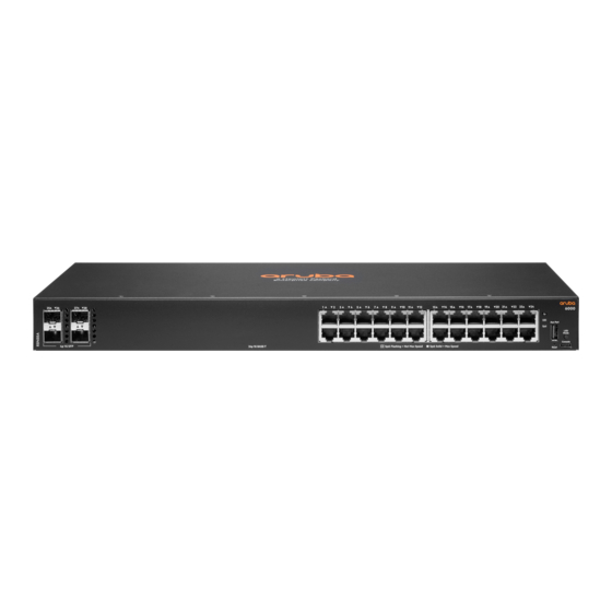
Testing the switch by resetting it Checking the switch LEDs Checking console messages Testing twisted-pair cabling Testing switch-to-device network communications Testing end-to-end network communications Restoring the factory default configuration Downloading new switch software Aruba 6000 & 6100 Switch Series Installation and Getting Started Guide...
Page 4
Crossover twisted-pair cable for 10 Mbps or 100 Mbps network connection Cable diagram Pin assignments Straight-through twisted-pair cable for 1000 Mbps network connections Cable diagram Pin assignments Support and Other Resources Accessing Aruba Support Accessing Updates Aruba Support Portal My Networking Warranty Information Regulatory Information Documentation Feedback...
Aruba 6100 24G 4SFP+ Switch (JL678A) Aruba 6100 12G Class4 PoE 2G/2SFP+ 139W Switch (JL679A) Related publications Start Here: Installation, Safety, and Regulatory Information for the Aruba 6000 and 6100 Switches and Accessories AOS-CX software manuals Power Over Ethernet (PoE) Planning and Implementation Guide for the ArubaOS-CX Switches...
Chapter 3 Introducing the switches Introducing the switches Aruba multiport switches are store-and-forward devices offering low latency for high-speed networking. Certain switch models also support Power over Ethernet (PoE) technologies and full network management capabilities. This chapter describes these switches with the following information:...
Page 8
Indicator of traffic activity. The bright - Green blink time is roughly proportional to the % of full bandwidth utilization of the port. Fault No fault Flash - Amber Fault Aruba 6000 & 6100 Switch Series Installation and Getting Started Guide...
Switch LEDs Function State Meaning PoE mode LED Indicates Port LEDs are PoE mode not selected showing PoE information (not applicable for non On - Green PoE mode selected PoE switches) Slow Flash - Amber Hardware failure PoE enabled port, PoE mode not selected On - Amber Hardware failure PoE enabled port, PoE mode selected...
Aruba 6000 24G Class4 PoE 4SFP 370W Switch Up to 30W, IEEE 802.3af/at 370W available PoE power (R8N87A) Aruba 6000 12G Class4 PoE 2G/2SFP 139W Switch Up to 30W, IEEE 802.3af/at 139W available PoE power (R8N89A) Aruba 6000 & 6100 Switch Series Installation and Getting Started Guide...
Page 11
Aruba Central: Network management software cloud platform. It offers IT organizations a simple, secure, and cost-effective way to manage and monitor Aruba switches and Aruba instant wireless APs. (Available in future Aruba Central release) Support for the Spanning Tree Protocol to eliminate network loops.
Page 12
Support for many advanced features to enhance network performance: For a description, see the AOS- CX guides for your switch. Ability to update the switch software. To download product updates, go to the Aruba Support Portal. An auxiliary port (USB Type-A connector) for updating switch software.
All models except JL679A and R8N89A may be shipped in a rack. This method uses the HPE X410 Universal Rack Mounting Kit (J9583A, J9583B). To order the J9583A or J9583B rack mounting kit, contact your Aruba sales representative. Included parts...
Mount devices installed in a rack or cabinet as low as possible. Put the heaviest devices at the bottom and progressively lighter devices positioned higher. To prevent the rack or cabinet from becoming unstable and/or falling over, ensure that it is adequately secured. Aruba 6000 & 6100 Switch Series Installation and Getting Started Guide...
If your installation requires a different power cord than the one supplied with the switch, be sure that the cord is adequately sized for the current switch requirements. In addition, be sure to use a power cord displaying the mark of the safety agency that defines the regulations for power cords in your country/region. The mark is your assurance that the power cord can be used safely with the switch.
15.3 cm (6 inches) from the top, sides, and back of the switch. Mounting Aruba 6000 and 6100 12G switches with ports facing upward is not supported. Physically stacking any switch model on top of a JL679A and R8N89A switch can interrupt the flow of warm air through the vents in the top of the JL679A and R8N89A switch and is not supported.
Page 19
(as shown in the following illustrations). Mounting brackets can also be attached at the middle of the switch. Aruba 6000 & 6100 Switch Series Installation and Getting Started Guide...
Page 20
For safe reliable installation, only use the screws provided in the accessory kit to attach the mounting brackets to the switch. 2. Secure the rack mounting brackets to a two-post rack as shown in the following illustrations. Flush Mounting in a two-post rack Mounting in a two-post rack at switch middle (missing or bad snippet)
For fanless models, attaching the four rubber feet to the bottom of the switch is required to provide the necessary thermal transfer space between the switch bottom and the horizontal surface. Wall mounting 12G switches Aruba 6000 and 6100 12G airflow Aruba 6000 & 6100 Switch Series Installation and Getting Started Guide...
Page 22
Aruba 12G switches are fan-less and rely on natural convection to maintain proper operating temperature. Aruba 12G switches (JL679A and R8N89A) can only be mounted with ports facing left, right or downward. Mounting the swtich with ports facing upward is not supported.
Page 23
3. Use a #1 Phillips (cross-head) screwdriver and attach the mounting brackets to the switch with the included 6-mm M4 screws. 4. Mount the switch to the wall using four screws (not included), applicable for the type of wall being Aruba 6000 & 6100 Switch Series Installation and Getting Started Guide...
used. Mounting holes To mount the JL679A and R8N89A switch using the holes located on the bottom of the switch, follow these steps: 1. In the required location, mark the position for the mounting screws. The hole-to-hole distance is 7 inch (178 mm) (x-axis) and 5.8 inch (147 mm) (y-axis).
(Optional) Insert up to four SFP or SFP+ transceivers in the fixed transceiver slots on the switch front panel. Connect network cables Connect network cables from network devices or your patch panels to the fixed RJ-45 ports and to any installed transceivers. SFP Installation Notes Aruba 6000 & 6100 Switch Series Installation and Getting Started Guide...
Use only an approved Laser Class 1 SFP transceiver. To ensure proper operation of your switch, use only the HPE Aruba SFP transceivers supported by your switch. Use only supported HPE Aruba SFP transceivers. Non-HPE Aruba SFP transceivers are not supported.
Page 27
Hot swapping SFP+ transceivers Supported SFP+ transceivers that you can install in your Aruba switch can be "hot swapped"–removed and installed while the switch is receiving power. However, disconnect the network cables from the SFP+ transceivers before hot-swapping them. When you replace a SFP+ transceiver with another transceiver of a different type, the switch may retain selected port-specific configuration settings that were configured for the replaced unit.
For a list of switch features available with and without an IP address, see the latest version of the Fundamentals Guide for your switch. Aruba 6000 & 6100 Switch Series Installation and Getting Started Guide |...
Check the port configuration: A port on your switch may not be operating as expected because it is administratively disabled in the configuration. It may also be placed into a "blocking" state by a protocol Aruba 6000 & 6100 Switch Series Installation and Getting Started Guide |...
operating on the port (dynamic VLANs), or LACP (dynamic trunking). For example, the normal operation of the spanning tree, MVRP, LACP, and other features may put the port in a blocking state. Use the switch console to determine the port configuration and verify that there is not an improper or undesired configuration of any of the switch features that may be affecting the port.
Page 31
Speed mode Indicates Port LEDs are Speed mode not selected showing speed information On - Green Speed mode selected UID LED User-configurable LED User defined the located LED : Aruba 6000 & 6100 Switch Series Installation and Getting Started Guide...
Page 32
If the power source and power cord are OK and this condition persists, the switch power supply may have failed. To get assist- ance, call your Aruba authorized network reseller, or use the electronic support services from Aruba to get assistance.
Page 33
"Auto" (auto negotiate), either straight-through or crossover cables can be used because of the switch "Auto-MDIX" feature and the Auto MDI/MDI-X feature of the 10/100/1000-T port. Aruba 6000 & 6100 Switch Series Installation and Getting Started Guide...
Page 34
Problem Solution NOTE: If the switch port configuration is changed to one of the fixed configuration options (for example, 100 Mbps/Full Duplex), then the port operates as MDI-X only and you must use the correct type of cable for the connection.
System Up Time timer to reset to zero. Checking the switch LEDs Diagnosing with the LEDs for information on interpreting the LED patterns and LED behaviors. Checking console messages Aruba 6000 & 6100 Switch Series Installation and Getting Started Guide...
Useful diagnostic messages may be displayed on the console screen when you reset a switch. Connect a PC running a VT-100 terminal emulator program or a standard VT-100 terminal to the switch console port. Configure the terminal to run at 115200 baud, and with the other terminal communication settings. When you reset the switch, note the messages that are displayed.
Downloading new switch software Software updates can be downloaded to the switch through several methods. For more information, see Support and Other Resources. Aruba 6000 & 6100 Switch Series Installation and Getting Started Guide...
Dimensions (W x D x H) Weight Aruba 6100 48G Class4 PoE 4SFP+ 370W Switch (JL675A) 17.4 x 12 x 1.73 in 11.07 lb (44.25 x 30.55 x 4.40 cm) (5.02 kg) Aruba 6000 & 6100 Switch Series Installation and Getting Started Guide |...
17.4 x 9.74 x 1.73 in 7.54 lb (44.25 x 24.73 x 4.40 cm) (3.42 kg) Aruba 6100 24G Class4 PoE 4SFP+ 370W Switch (JL677A) 17.4 x 10.56 x 1.73 in 9.24 lb (44.25 x 26.82 x 4.40 cm) (4.19 kg) Aruba 6100 24G 4SFP+ Switch (JL678A) 17.4 x 7.92 x 1.73 in...
Safety Lasers EN 60825-1:2007 / IEC 60825-1:2007 Class 1 Class 1 Laser Products / Laser Klasse 1 (Applicable for accessories - Optical Transceivers only) Safety Europe EN 60950-1:2006 +A11:2009 +A1:2010 +A12:2011 + A2:2013 EN 62368-1:2014 +A11:2017 UL 60950-1 2nd Ed. UL 62368-1:2014 Canada CAN/CSA-C22.2 No.
Page 42
Class 1 Laser Product Laser Klasse 1 10-Gig LR IEEE 802.3ae 10GBASE-LR EN/IEC 60825 Class 1 Laser Product Laser Klasse 1 Power over Ethernet IEEE 802.3at (PoE) over 2-pairs IEEE 802.3af Aruba 6000 & 6100 Switch Series Installation and Getting Started Guide...
This section includes switch connector information and network cable information for cables used with the Aruba switches. Incorrectly wired cabling is a common cause of problems for LAN communications. Aruba recommends that you work with a qualified LAN cable installer for assistance with your cabling requirements.
When testing your cabling, be sure to include the patch cables that connect the switch and other end devices to the patch panels on your site. The patch cables are frequently overlooked when testing cable and they must also comply with the cabling standards. Technology distance specifications Table 16: Technology distance specifications Multimode fiber-...
Straight-through twisted-pair cable for 10 Mbps or 100 Mbps network connections Because of the Aruba Auto-MDIX operation of the 10/100 ports on the switch, for all network connections, to PCs, servers or other end nodes, or to hubs or other switches, you can use straight-through cables.
receive + <------------ transmit + receive - <------------ transmit - transmit + ------------> receive + transmit - ------------> receive - Crossover twisted-pair cable for 10 Mbps or 100 Mbps network connection The Auto-MDIX operation of the 10/100 ports on the switch also allows you to use crossover cables for all network connections, to PCs, servers or other end nodes, or to hubs or other switches.
Pins 4 and 5 on connector "A" must be wired as a twisted pair to pins 4 and 5 on connector "B". Pins 7 and 8 on connector "A" must be wired as a twisted pair to pins 7 and 8 on connector "B". Aruba 6000 & 6100 Switch Series Installation and Getting Started Guide...
Software licensing https://lms.arubanetworks.com/ End-of-Life information https://www.arubanetworks.com/support-services/end-of-life/ Aruba software and documentation https://asp.arubanetworks.com/downloads Accessing Updates You can access updates from the Aruba Support Portal or the HPE My Networking Website. Aruba 6000 & 6100 Switch Series Installation and Getting Started Guide |...
Aruba Support Portal https://asp.arubanetworks.com/downloads If you are unable to find your product in the Aruba Support Portal, you may need to search My Networking, where older networking products can be found: My Networking https://www.hpe.com/networking/support To view and update your entitlements, and to link your contracts and warranties with your profile, go to the Hewlett Packard Enterprise Support Center More Information on Access to Support Materials page: https://support.hpe.com/portal/site/hpsc/aae/home/...
Need help?
Do you have a question about the 6000 Series and is the answer not in the manual?
Questions and answers