Table of Contents
Advertisement
Quick Links
Advertisement
Chapters
Table of Contents
Troubleshooting

Related Manuals for Omron KE1


Summary of Contents for Omron KE1
- Page 1 Model KE1 Smart Power Mersuring Monitor User's Manual Catalog No. N176-E1-01...
-
Page 3: Introduction
Thank you for purchasing the Model KE1. The Model KE1 is a board built-in type Smart Power Monitor. The Model KE1 is divided into the following units. The operation is performed by using the master unit independently or connecting slave units. -
Page 4: Items On Which You Agree By Using This Product
If the fault could not be expected based on the level of science and technology as of the time delivery from Omron. If the fault is due to reasons not attributable to Omron, such as natural disasters Also, the warranty stated in this manual refers to the warranty for a single unit of this product, and damage caused by faults with this product is out-of-scope for the warranty. - Page 5 4. Specification Change The specifications of this product and accessories may be changed if necessary for reasons such as improvements. Please contact an Omron sales representative to check the current specifications of this product. 5. Applicable scope The details given above are based on the assumption that the product will be traded and used within Japan If trading and using disparate outside Japan, please contact an Omron sales representative.
-
Page 6: Safety Precautions
Safety Precautions Symbols for Safe Use and Their Meanings This manual employs the following indications or symbols for points to note for the user to use Model KM1 safely. The points to note shown here indicate important details related to safety. You must adhere to them. - Page 7 Display of warning Caution Ignition may occur and this may cause damage to objects. Make sure you tighten terminal screws with standard tightening torque. Recommended tightening torque of terminal screw: 0.69 to 0.88 Nm After the screw is tightened, ensure that it is not tilted. Explosion may cause a medium or minor degree of injuries or physical loss or damage.
-
Page 8: Safety Points
Use the DIN rail of 35 mm in width (Model PFP-50N/-100N manufactured by OMRON). When wiring on the main body of the product, use a crimp-style terminal suitable for M3.5 screw. -
Page 9: Requests For Installation
19) Use the dedicated CT, ZCT and dedicated CT cable specified by OMRON. Model KM20-CTF-5A Model KM20-CTF-50A Model KM20-CTF-100A Split type Dedicated Model KM20-CTF-200A Model KM20-CTF-400A Model KM20-CTF-600A Through Model KM20-CTB-5A/50A type Split core type for earth Model K6ER-CN22 (With cable) -
Page 10: Precautions For Use
Precautions for Use Make correct settings according to the targets to be monitored. Do not hold and pull a cable. When discarding this product, appropriately treat it as an industrial waste. If this product is used in the environment of overvoltage category III, install a varistor between lines on the power supply of this product/outside voltage measurement input. -
Page 11: Relevant Manuals
Describes the details of communication for the Model Smart Power Monitor KM1/KE1 series Communication Manual for Smart Measurement and Monitoring Instrument GAMS-010 Model KM1/KE1 KM1/KE1-Setting Describes how to use setting tools for the Model KM1/KE1 User’ s Manual series and the setting procedure. -
Page 12: Abbreviation
*1 Slaves can be connected. *2 Can be connected to the measurement master. *3 Can be operated independently. *4 Product of KE1. In addition, for the combinations, refer to Page A-20. Manual Revision History The manual revision symbol is given at the end of the catalog number on the front cover and the bottom left of the back cover of the manual. -
Page 13: Table Of Contents
Installation of dedicated CT, ZCT ..............2-12 ■ Wire connection and installation of dedicated CT, ZCT .........2-14 Input/output configuration and example of wiring diagram......2-16 ■ Model KE1-PGR1C-FLK..................2-16 ■ Model KE1-PVS1C-FLK ..................2-18 ■ Model KE1-VSU1B-FLK ..................2-20 ■ Model KE1-VAU1B-FLK..................2-22 ■ Model KE1-CTD8E....................2-24 ■... - Page 14 Chapter 3 Functions .................3-1 List of functions..................3-2 Basic functions ..................3-3 ■ Applicable phase wire ..................3-3 ■ Synchronization selection for measuring block ..........3-3 ■ Dedicated CT type.................... 3-3 ■ VT ratio ......................3-4 ■ CT ratio......................3-4 ■...
- Page 15 ■ Main part specifications..................A-3 ■ Protection functions..................A-5 ■ Accessories ...................... A-6 Dedicated CT and ZCT ..................A-7 ■ Specification ..................... A-7 ■ External dimensions ..................A-9 List of parameters....................A-13 List of data logging items..................A-18 Model KM1/KE1 combination list .................A-20 XIII...
- Page 17 Chapter 1. Overview Main features and functions ................... 1-2 Main features ....................1-2 Main functions ....................1-3 Function by unit..................1-3 Output function..................1-3 Communication function ................1-4 Logging function of measurement data ........... 1-4 ...
-
Page 18: Chapter 1 Overview
* For information on the combination of units that can be connected, refer to page A-20. *1 CompoWay/F is a unified communication procedure within Omron’s generic serial communication. It has commands conforming to the time-proven FINS in the unified frame format and Omron's programmable controller, making easy the communication between the personal computer and the components. -
Page 19: Main Functions
Main features and functions Main functions This section describes main functions of Model KE1. Function by unit PGR1C (Electric power/leakage) : Allows measuring current, voltage, and electric power and detecting leakage. PVS1C (Electric power/voltage sag) : Allows measuring current, voltage, and electric power and detecting voltage sag. -
Page 20: Communication Function
Chapter 1 Overview 2) Alarm output PGR1C PVS1C VSU1B VAU1B CTD8E ZCT8E (Electric (Electric (Voltage (Voltage/ (ZCT power/leakage) power/voltage sag) current) extension) extension) sag) × ○ ○ × × × Voltage sag alarm ○ × × × × ○ Leakage alarm ○... -
Page 21: Name And Function Of Each Part
Name and function of each part Name and function of each part Name of each part [1] DIN hook A hook, which is mounted in each of the upper and lower parts of the main body, is used to install the product in the DIN rail or on a wall. -
Page 22: Explanation Of The Display Unit
Chapter 1 Overview Explanation of the display unit P G R 1C P W R A LM C T 1 C T 2 C T 3 Z C T (Electric power /leakage) C O N N C O M M O U T 1 O U T 2 P V S 1C... -
Page 23: Setting Switch
* For information on Model KM1 series, refer to "Model KM1 User's Manual" (KANC-701). * For information on the communication slave (DRT (DeviceNet)), refer to Model KE1 DeviceNet Communication Unit User's Manual" (SGTE-718). How to use setting switches ... -
Page 24: System Configuration
Chapter 1 Overview System configuration Model type In this manual, an object that has been set in a state where various measurements and monitor can be performed is defined as "System." This product allows an independent unit (single-unit configuration) or multiple units connected (multiple-unit connection configuration) to perform data measurements and status monitor. -
Page 25: Configuration
*1. For information on the communication slave, refer to "Model KE1 DeviceNet Communication Unit User's Manual" (SGTE-718). * 2. For information on the combination of units, refer to "Model KM1/KE1 Series List of Combinations" on page A-20. Multiple-unit connection Connecting the measurement master to a functional slave or a CT extension slave can expand functions. -
Page 26: Minimum Configuration
A maximum of four units, including functional Only one communication slave Only one measurement master slave and CT extension slave units * For the communication slave (DRT (DeviceNet)), refer to "Model KE1 User's Manual" (SGTE-717) and "Model KE1 User's Manual for DeviceNet Communication Unit (SGTE-718). 1-10... -
Page 27: Multiple-System Configuration
System configuration Multiple-system configuration Model KE1 is a system containing a maximum of six units. Multiple-system configuration can be made via RS-485 communication. The diagram below shows an example of the configuration consisting of the following multiple systems where masters are connected with the wire for RS-485 communication. The three... -
Page 28: Format Standard
Chapter 1 Overview Format standard Format standard K 1 - - F L K [1] [2] [3] [1] K Product of measurement monitor [2] E Smart Measurement and Monitoring Instrument Smart Power Monitor Smart Measurement and Monitoring Instrument [3] 1 Series No. - Page 29 ● Terminal arrangements and input/output configuration......2-16 ● Function of terminal ................2-16 ● Example of wiring diagram..............2-17 ■ Model KE1-PVS1C-FLK ................2-18 ● Terminal arrangements and input/output configuration......2-18 ● Function of terminal ................2-18 ● Example of wiring diagram..............2-19 ■...
-
Page 30: Flow Before Use
* Between terminals [1] and [2] in each unit, apply the power voltage. * For the setting, use KM1/KE1-Setting. For how to use KM1/KE1-Setting, refer to "KM1/KM1 User's Manual for Setting Tool" (GAMS-010). Download KM1/KE1-Setting and the manual at i-Web (http://www.fa.omron.co.jp/). -
Page 31: Setting Example
Flow before use ■ Setting example System Configuration Master --- PGR1C (Electric power/leakage) Slave --- VSU1B (Voltage sag) ZCT8E (ZCT extension) Purpose Measurement of power of 3-phase 3-wire line and monitoring of voltage sag Monitoring of leakage in pieces of equipment A to F connected to 3-phase 3-wire line Setting switch Set the Pin no. -
Page 32: Chapter 2 Preparation
: 7 bits Stop bit length : 2 bits Vertical parity : Even Transmission wait time : 20 ms Electrical system 1 applicable phase wire KE1-PGR1C-FLK RS-485 Output ZCT Input Power voltage Measurement block 1 (CT input of system 1) - Page 33 Stop bit length : 2 bits Vertical parity : Even Transmission wait time : 20 ms Electrical system 1 applicable phase wire KE1-VSU1B-FLK RS-485 Output Power voltage ZCT8E (ZCT extension) Leakage comparison value 1 : 30 mA Leakage comparison value 2...
-
Page 34: Installation
Chapter 2 Preparation Installation ■ External dimensions (unit: mm) 45 in width X 96 in height X 90 in depth (Protruding portion is not included) * Dimensions put in parentheses are applicable when DIN hook is pulled out. -
Page 35: Connection Method
Installation ■ Connection method Using horizontally connecting hooks and connection connectors, connect adjacent units to each other. ● Horizontally connecting hook This hook is used to securely fix units to each other on the DIN rail. Installation procedure Slide the white, horizontally connecting hooks on top and at the bottom of the product until a clicking sound is heard and lock. -
Page 36: Connector
Chapter 2 Preparation ● Connector This connector is used to connect units to each other. Inter-unit communication can be carried out to expand functions. Installation procedure Lift the cover on top of the product and set the connection connector. Close the cover before use. -
Page 37: Installation Procedure
End plate Model PFP-M (2 pieces) Installation direction The installation direction of Model KE1 has been determined. As shown below, place the DIN rail vertical to the ground and install it in the horizontal direction. Horizontal: Vertical: ... - Page 38 Chapter 2 Preparation Installation procedure Lower the DIN hook, hook the upper claw on the DIN rail, and push it until the DIN hook can be locked. Then lock it by raising the hook. [2] Hook the upper ②上部の爪を claw on the rail レールにかける...
-
Page 39: Installation On A Wall
Installation ● Installation on a wall If the product is used as a single unit, it can be installed on a wall. When using multiple units, be sure to install them in the DIN rail. Installation procedure Installation procedure ... -
Page 40: Installation Of Dedicated Ct, Zct
Use of dedicated CTs in a circuit requires all the CTs to have the same standard. The standard of the dedicated CTs to be used should match the settings of the dedicated CT of Model KE1. A dedicated CT has its polarity. Carry out wiring correctly between (K) and (L). - Page 41 Installation of dedicated CT, ZCT 【CT】 Load side 負荷側 (L) Load side Hook for 分割/ split/fixing type Loading 電源側 固定用フック side (K) For fixing a banding 結束バンド等 band, etc. の固定用 Terminal cover on the secondary CT二次側 Loading side side of dedicated CT 端子カバー...
-
Page 42: Wire Connection And Installation Of Dedicated Ct, Zct
Chapter 2 Preparation ■ Wire connection and installation of dedicated CT, ZCT This section describes the wire connection for each phase wire and the installation of dedicated ● Connection of dedicated CT Single-phase 2-wire Single-phase 3-wire 単相 3 線式 単相 2 線式 Product Product 製品... -
Page 43: Connection Of Dedicated Zct
Installation of dedicated CT, ZCT ● Connection of dedicated ZCT Single-phase 2-wire Single-phase 3-wire Loading side Load side Loading side Load side Product Product To ZCT input To ZCT input 3-phase 3-wire 3-phase 4-wire Loading side Load side Load side Loading side Product Product... -
Page 44: Input/Output Configuration And Example Of Wiring Diagram
Input/output configuration and example of wiring diagram Terminal arrangements should be confirmed according to the numbers printed on the side face of the product and on the terminal block. ■ Model KE1-PGR1C-FLK ● Terminal arrangements and input/output configuration ● Function of terminal ①... -
Page 45: Example Of Wiring Diagram
● Example of wiring diagram ・Single-2 wire ・Single-3 wire Power supply side (K) Power supply side (K) Load side (L) R N T T input KE1-PGR 1C-FLK KE1-PGR 1C-FLK ZCT input RS-485 communication RS-485 communication CT3 input CT3 input Transistor output... -
Page 46: Model Ke1-Pvs1C-Flk
Chapter 2 Preparation ■ Model KE1-PVS1C-FLK ● Terminal arrangements and input/output configuration ● Function of terminal ① Power voltage ⑨ ⑰ CT-3S * (AC100 to 240 V) ② ⑩ ⑱ CT-3L * ③ ⑪ ⑲ Solid-state relay output ④ ⑫... -
Page 47: Example Of Wiring Diagram
Input/output configuration and example of wiring diagram ● Example of wiring diagram ・Single-2 wire ・Single-3 wire Power supply side (K) Power supply side (K) Load side (L) R N T KE1-PVS1C-FLK KE1-PVS1C-FLK RS-485 communication RS-485 communication CT3 input CT3 input Transistor output Transistor output... -
Page 48: Model Ke1-Vsu1B-Flk
Chapter 2 Preparation ■ Model KE1-VSU1B-FLK ● Terminal arrangements and input/output configuration ● Function of terminal ① Power voltage ⑨ ⑰ (AC100 to 240 V) ② ⑩ ⑱ ③ ⑪ ⑲ 1a relay output ④ ⑫ ⑳ ⑤ ⑬ Measurement voltage input P1 Solid-state relay output ⑥... -
Page 49: Example Of Wiring Diagram
Input/output configuration and example of wiring diagram ● Example of wiring diagram ・Single-2 wire ・Single-3 wire Power supply side (K) Power supply side (K) R N T KE1-VSU1B-FLK KE1-VSU1B-FLK RS-485 communication RS-485 communication Solid-state relay output Solid-state relay output 1a relay output... -
Page 50: Model Ke1-Vau1B-Flk
Chapter 2 Preparation ■ Model KE1-VAU1B-FLK ● Terminal arrangements and input/output configuration ● Function of terminal ① Power voltage ⑨ ⑰ CT-3S * (AC100 to 240 V) ② ⑩ ⑱ CT-3L * ③ ⑪ ⑲ 1a relay output 1 ④... -
Page 51: Example Of Wiring Diagram
● Example of wiring diagram ・Single-2 wire ・Single-3 wire Power supply side (K) Power supply side (K) Load side (L) R N T T KE1-VAU1B-FLK KE1-VAU1B-FLK RS-485 communication RS-485 communication CT3 input CT3 input 1a relay output 1a relay output... -
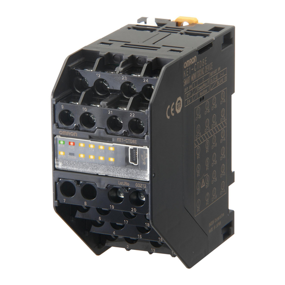
Page 52: Model Ke1-Ctd8E
* To measure electric power with CTD8E, assign the measurement blocks 1 and 2 to the system 1 (system 2) of the measurement master. The setting is made in KM1/KE1-Setting. * The assignment to the system 2 is available only when the unit is connected to Model KM1-PMU2A-FLK in Model KM1 series. -
Page 53: Example Of Wiring Diagram
Load CT7 input Load CT6 input Load CT5 input Load Model KE1-CTD8E does not operate as a single unit. For the operation, be sure to connect it to the CT4 input measurement master. Load CT3 input The number CT inputs required differ depending on the line type. - Page 54 Chapter 2 Preparation 3-phase 3-wrie Example: For power measurement on 4 circuits Power supply side (K) Load Model KE1-CTD8E does not operate as a single Load unit. For the operation, be sure to connect it to the Load measurement master.
-
Page 55: Model Ke1-Zct8E
Input/output configuration and example of wiring diagram ■ Model KE1-ZCT8E ● Terminal arrangements and input/output configuration ● Function of terminal ① ⑨ CT-7K * ⑰ CT-3K * ② ⑩ CT-7L * ⑱ CT-3L * ③ ⑪ CT-8K * ⑲ CT-4K * 1a relay output ④... -
Page 56: Example Of Wiring Diagram
ZCT6 input Load ZCT5 input Load KE1-PGR1C-FLK KE1-ZCT8E Model KE1-ZCT8E does not function as a Load ZCT4 input single unit. Be sure to connect it to the measurement master. Load According to the type of wire, the number of ZCT inputs required for the measurement of... - Page 57 Load ZCT6 input Load ZCT5 input Load KE1-PGR1C-FLK KE1-ZCT8E Model KE1-ZCT8E does not function as a single unit. Be sure to connect it to the Load ZCT4 input measurement master. According to the type of wire, the number of Load...
-
Page 58: Wiring
Chapter 2 Preparation Wiring ■ Requests for wiring Do not change the terminal screws, but use existing screws. To prevent being affected by noise, wiring of signal line should be different from that of power line. Cable to be used for wiring terminals excepting CT should be twist pair AWG25 (whose cross-sectional area is 0.205 mm2) to AWG12 (whose cross-sectional area is 3.309 mm2). -
Page 59: Usb Port
Wiring ● USB port Connecting Model KE1 and a PC via a USB cable can make settings and read measurement values. In addition, supplying power from a PC via USB (driving USB bus power) can make settings only. For the functions available via a USB port, refer to the table below. -
Page 60: Ct Input
Chapter 2 Preparation ● CT input PGR1C PVS1C VSU1B VAU1B CTD8E ZCT8E (Electric power (Electric power (Voltage sag) (Voltage/current) (CT extension) (ZCT extension) /leakage) /voltage sag) CT/ZCT CT/ZCT CT/ZCT CT/ZCT CT/ZCT CT/ZCT ○/○ ○/× ×/× ○/× ○/× ×/○ O: With input X: Without input [PGR1C (power/leakage), PVS1C (power/voltage sag), VAU1B (voltage/current)] The connection terminal of the dedicated CT and the number of circuits to be measured in each phase and wire system are shown below. -
Page 61: Zct Input
When using RS-485 communication functions, connect a communication cable between terminals [8] and [7]. B(+) A termination resistor must be connected to each end 形 KM1 Model KE1 RS-485 of the transmission path. Each termination resistor A(-) should be 120 Ω (1/2 W). -
Page 62: Output
Chapter 2 Preparation ● Output PGR1C PVS1C VSU1B VAU1B CTD8E ZCT8E (Electric power (Electric power (Voltage sag) (Voltage/current) (CT extension) (ZCT extension) /leakage) /voltage sag) ○ ○ ○ ○ ○ ○ O: With output To enable alarm output, connect wires in each unit as shown in the table and diagram below. PGR1C PVS1C CTD8E... -
Page 63: Chapter 3 Functions
Chapter 3. Functions List of functions ..................3-2 Basic functions ................... 3-3 Applicable phase wire ......................3-3 Synchronization selection for measuring block .............. 3-3 Dedicated CT type........................3-3 VT ratio............................3-4 CT ratio............................3-4 Low-cut function ........................3-5 ... -
Page 64: List Of Functions
Functions 3.1 List of functions PGR1C PVS1C VSU1B VAU1B CTD8E ZCT8E (Electric power (Electric power (Voltage sag) (Voltage/curr (ZCT /leakage) /voltage sag) ent) extension) extension) Single-phase 2-wire ○ ○ ○ ○ ○ ○ Single-phase 3-wire ○ ○ ○ ○ ○ ○... -
Page 65: Basic Functions
Basic functions 3.2 Basic functions Applicable phase wire PGR1C PVS1C VSU1B VAU1B CTD8E ZCT8E (Electric power (Electric power (Voltage sag) (Voltage/current) (CT extension) (ZCT extension) /leakage) /voltage sag) ○ ○ ○ ○ ○ × O: With setting X: Without setting •... -
Page 66: Vt Ratio
PMU2A (power two-system). <When 5ACT is connected> 二次側 5A 出力の General CT of secondary 5 A output 汎用 CT 専用 CT Dedicated CT ( 形 KM20-CTF-5A Model KM20-CTB-5A or Model KM20-CTB-5A/50A または形 KM20-CTB-5A/50A) Model KE1 形 KM1 1000A... -
Page 67: Low-Cut Function
Basic functions Low-cut function • This function forcibly sets the current measurement value to 0 when the current value becomes less than (standard current of CT) X (setting ratio). • The ratio of an unmeasured load current to the standard current is set. •... -
Page 68: Logging Function
Functions Logging function PGR1C PVS1C VSU1B VAU1B CTD8E ZCT8E (Electric power (Electric power (Voltage sag) (Voltage/current) (CT extension) (ZCT extension) /leakage) /voltage sag) ○ ○ ○ ○ × × O: With function X: Without function • Six data logging areas have been prepared. Each area can save 588 pieces of data (up to 6 items can be set.) •... -
Page 69: Measurement Function
Basic functions Measurement function Active power PGR1C PVS1C VSU1B VAU1B CTD8E ZCT8E (Electric power (Electric power (Voltage sag) (Voltage/current) (CT extension) (ZCT extension) /leakage) /voltage sag) ○ ○ × × ○ × O: With measurement function X: Without measurement function Measurement range: -99999999.9 to 99999999.9 W (minimum unit: 0.1 W) The following active powers are measured: instantaneous value, maximum value, and minimum value. -
Page 70: Current
Functions Current PGR1C PVS1C VSU1B VAU1B CTD8E ZCT8E (Electric power (Electric power (Voltage sag) (Voltage/current) (CT extension) (ZCT extension) /leakage) /voltage sag) ○ ○ × ○ ○ × O: With measurement function X: Without measurement function Measurement range: 0.000 to 9999.999 A (minimum unit: 0.001 A) The following currents are measured: instantaneous value, maximum value, and minimum value. -
Page 71: Frequency
Basic functions Frequency PGR1C PVS1C VSU1B VAU1B CTD8E ZCT8E (Electric power (Electric power (Voltage sag) (Voltage/current) (CT extension) (ZCT extension) /leakage) /voltage sag) ○ ○ ○ ○ × × O: With measurement function X: Without measurement function range: 45.0 to 65.0 Hz (minimum unit: 0.1 Hz) Measurement ... -
Page 72: Voltage Sag (Instantaneous Voltage Drop) Detection Function
Functions 3-3 Voltage sag (instantaneous voltage drop) detection function When voltage sag (instantaneous voltage drop) detection occurs, the voltage sag detection is reported with the lighting of ALM on the display and the signal output from the output terminal (Note 1). For the past eight voltage sags, voltage sag occurrence time and voltage measured around the occurrence are stored as voltage sag history. -
Page 73: Setting Of Conditions For Voltage Sag Detection
Voltage sag detection is determined by measured voltages without being affected by the VT ratio setting. * Set each item in KM1/KE1-Setting. * If sag detection voltage is set to 0 V, detection for 0 V may be unavailable due to the effect of surrounding environment. -
Page 74: Operation At The Time Of Power Supply Voltage Sag (Power Failure)
Functions Operation at the time of power supply voltage sag (power failure) If power supply voltage sag (power failure) occurs, storing of voltage sag history data and output from the output terminal depend on whether backup power supply is available. Availability of backup power supply State of State of power supply... -
Page 75: Examples Of Operations For Voltage Sag Detection
3-3 Voltage sag (instantaneous voltage drop) detection function Examples of operations for voltage sag detection The following diagrams ① to ③ show the examples of operations available when the voltage between R and S is subject to monitoring of voltage sag in 3-phase 3-wire system. ①... -
Page 76: Leakage Detection Function
Functions 3.4 Leakage detection function This function allows detecting electric leakage arising from insulation deterioration of electrical machinery and apparatus in a low voltage circuit. PGR1C PVS1C VSU1B VAU1B CTD8E ZCT8E (Electric power (Electric power (Voltage sag) (Voltage/current) (CT extension) (ZCT extension) /leakage) /voltage sag) -
Page 77: Installation Examples
Leakage detection function Installation examples Example of correct installation Examples of incorrect installation Have all of 2-, wire 3- wire, or 4-wire run through the opening of Malfunction arises from the load current of the neutral line. ZCT in single-phase 2-wire, single phase 3-wire, 3-phase 3-wire, or 3-phase 4-wire systems Model Type B earth wire... -
Page 78: Voltage/Current Monitoring Function
Functions 3.5 Voltage/current monitoring function Overvoltage/undervoltage PGR1C PVS1C VSU1B VAU1B CTD8E ZCT8E (Electric power (Electric power (Voltage sag) (Voltage/current) (CT extension) (ZCT extension) /leakage) /voltage sag) ○ ○ ○ ○ × × O: With function X: Without function Set thresholds are used to monitor the status of voltage. OR condition (threshold crossing in any one of the phases) is used to determine the issuing of an alarm. -
Page 79: Open Phase (Fixed Unbalance Factor)
Voltage/current monitoring function Open phase (Fixed unbalance factor) PGR1C PVS1C VSU1B VAU1B CTD8E ZCT8E (Electric power (Electric power (Voltage sag) (Voltage/current) (CT extension) (ZCT extension) /leakage) /voltage sag) ○ ○ ○ ○ × × O: With function X: Without function The occurrence of an open phase is determined when the calculation result of (max. -
Page 80: Output Function
Functions 3.6 Output function Ouptut terminal 1/output terminal 2/output terminal 3 function setting PGR1C PVS1C VSU1B VAU1B CTD8E ZCT8E (Electric power (Electric power (Voltage sag) (Voltage/current) (CT extension) (ZCT extension) /leakage) /voltage sag) ○ ○ ○ ○ ○ ○ O: With setting •... -
Page 81: Voltage Sag Alarm Output
Output function Pulse output unit PGR1C PVS1C VSU1B VAU1B CTD8E ZCT8E (Electric power (Electric power (Voltage sag) (Voltage/current) (CT extension) (ZCT extension) /leakage) /voltage sag) ○ ○ × × × × O: With setting X: Without setting Available when a pulse output is assigned to the output setting. Any pulse output unit can be set. -
Page 82: Leakage Alarm Output
Functions Leakage alarm output PGR1C PVS1C VSU1B VAU1B CTD8E ZCT8E (Electric power (Electric power (Voltage sag) (Voltage/current) (CT extension) (ZCT extension) /leakage) /voltage sag) ○ × × × × ○ O: With alarm X: Without alarm Selecting Leakage in the output terminal setting allows the output of leakage alarms from the output terminal. -
Page 83: Alarm Output
Output function Alarm output • Alarm output upper/lower limit threshold, alarm output hysteresis, alarm output on-delay can be set. • Setting hysteresis can prevent frequently turning ON/OFF an alarm even when a measurement value varies near the alarm output judgment value. •... -
Page 84: Active Input Setting
Functions Active input setting PGR1C PVS1C VSU1B VAU1B CTD8E ZCT8E (Electric power (Electric power (Voltage sag) (Voltage/current) (CT extension) (ZCT extension) /leakage) /voltage sag) ○ ○ × ○ ○ ○ O: With setting X: Without setting Set the input (CT input/ZCT input) subject to monitoring in the alarm item setting and leakage alarm. -
Page 85: Over Current Alarm Output
Output function Over current alarm output PGR1C PVS1C VSU1B VAU1B CTD8E ZCT8E (Electric power (Electric power (Voltage sag) (Voltage/current) (CT extension) (ZCT extension) /leakage) /voltage sag) ○ ○ × ○ ○ × O: With alarm X: Without alarm • This function is available when output terminal function setting is selected as an alarm after the setting of alarm parameter setting and alarm output setting. -
Page 86: Under Voltage Alarm Output
Functions Under voltage alarm output PGR1C PVS1C VSU1B VAU1B CTD8E ZCT8E (Electric power (Electric power (Voltage sag) (Voltage/current) (CT extension) (ZCT extension) /leakage) /voltage sag) ○ ○ ○ ○ × × O: With alarm X: Without alarm • This function is available when output terminal function setting is selected as an alarm after the setting of alarm parameter setting and alarm output setting. -
Page 87: Other Functions
OFF, ON (Default: OFF) Note 1: The simple measurement function is unavailable when the measurement master of Model KE1 series is connected. The function is available when the measurement master of Model KM1 series is connected. Electric energy conversion coefficient... -
Page 88: Initialization
Functions Initialization Initialization is available from KM1/KE1-Setting. • Setting value initialization : Initializes setting values excepting time setting. • MAX/MIN initialization : Initializes maximum and minimum values. • Measurement history initialization : Initializes items to be logged. • Alarm history initialization : Initializes alarm histories. -
Page 89: Chapter 4 Troubleshooting
Chapter 4. Troubleshooting Flow of troubleshooting ..............4-2 Assume based on operation indicator LED........4-3 Assume based on the status ............4-4 Assume based on phenomena............4-5... -
Page 90: Flow Of Troubleshooting
If no problem is found after the check, perform detailed investigation based on communication functions. Check the condition by reading the status of the Model KE1 according to Assumption from status communication functions. 4.3 To "Assume based on the status"... -
Page 91: Assume Based On Operation Indicator Led
Assume based on operation indicator LED Assume based on operation indicator If the power (PWR) lamp of the measurement master, CT expansion slave, or function slave is flashing, it indicates that an error has occurred. Operation indicator LED Assumable cause Measures CONN COMM... -
Page 92: Assume Based On The Status
By reading the status through communication, you can confirm the condition of unit. The status is made up of 32 bits: bit 1 indicating the occurrence and bit 0 indicating non-occurrence (mode of operation 1: stop; 0: operation). (For the status of each model, refer to "Model KM1/KE1 Communication Manual" (SGTE-719).) -
Page 93: Assume Based On Phenomena
Assume based on phenomena Before you think the product is malfunctioning If Model KE1 does not operate normally, check applicable items listed below before making a request for repair. If the product does not operate normally despite your check, we would like you to return the product to us via our sales division. - Page 94 Troubleshooting When Phenomenon Items to be checked Action to be taken Reference page The primary current of Check that the When the primary current of inverter is measured, the inverter cannot be selected dedicated CT the crest value is several times larger than the measured correctly.
- Page 95 【ZCT】Indoor split core type ...............A-10 【ZCT】Outdoor split core type.............A-10 【ZCT】Indoor through type..............A-11 【ZCT】Outdoor through type...............A-11 Outdoor slit core type................A-12 List of parameters..................A-13 List of data logging items................A-18 Model KM1/KE1 combination list............... A-20...
-
Page 96: Appendix
Appendix Product specifications Rating of main unit PGR1C PVS1C VSU1B VAU1B CTD8E ZCT8E Model (Electric power (Electric power (Voltage sag) (Voltage/current) (CT extension) (ZCT extension) Item /leakage) /voltage sag) Applicable circuit Single-phase 2-wire, single-phase 3-wire, 3-phase 3-wire, 3-phase 4-wire Max. -
Page 97: Main Part Specifications
Product specifications Main part specifications Model PGR1C PVS1C VSU1B VAU1B CTD8E ZCT8E (Electric power (Electric power (Voltage sag) (Voltage/current) (CT extension) (ZCT extension) Item /leakage) /voltage sag) Accuracy Voltage ±1.0% FS ±1 digit (*1) * However, intra Vtr voltage shall be ±2.0% FS ±1digit under the same conditions. Current ±1.0% FS ±1 digit ±1.0% FS ±1 digit... - Page 98 Communication Protocol Communication protocol switching, OFF: CompoWay/F ON: Modbus Synchronous Refer to Model KM1/KE1 Communication Manual (SGTE-719). system Setup of unit CompoWay/F:0~99, Modbus:1~99 * If switching operation switches the protocol to Modbus when the unit No. setting is set to 0, the unit no. setting value is automatically changed to 1.
-
Page 99: Protection Functions
Product specifications Protection functions Model PGR1C PVS1C CTD8E ZCT8E VSU1B VAU1B (Electric power (Electric power (ZCT (Voltage sag) (Voltage/current) Item /leakage) /voltage sag) extension) extension) Active power Operation setting range Upper limit alarm: Upper limit alarm : monitor -120000000 to 120000000 W -120000000 to Lower limit alarm: 120000000 W... -
Page 100: Accessories
Appendix Model PGR1C PVS1C CTD8E ZCT8E VSU1B VAU1B (Electric power (Electric power (ZCT (Voltage sag) (Voltage/current) Item /leakage) /voltage sag) extension) extension) Leakage Operation setting range 30 to 1,000 mA 30 to 1,000 mA monitoring Operation characteristics ±5% rdg ±5% rdg (30 to 200 mA) (30 to 200 mA) ±1% FS... -
Page 101: Dedicated Ct And Zct
Dedicated CT and ZCT Dedicated CT and ZCT ■ Specification 【CT】 Model Split type Model Model Model Model Model Model Item KM20-CTF-5A KM20-CTF-50A KM20-CTF-100A KM20-CTF-200A KM20-CTF-400A KM20-CTF-600A Primary standard 50 A 100 A 200 A 400 A 600 A current Secondary standard 1.67 mA 16.7 mA... - Page 102 Appendix 【ZCT】 ・Split core type Model Indoor split core type Outdoor split core type Item Model OTG-CN52 Model OTG-CN77 Model OTG-CN112 Model OTG-CN36W Primary standard current 200 A 400 A 600 A 150 A Insulation resistance Between charging portion and earth: 100 MΩ or more (500 DCV megger) Voltage withstood Between charging portion and earth: 2200 VAC 1 min.
-
Page 103: External Dimensions
Dedicated CT and ZCT External dimensions (unit: mm) 【CT】Split type Model KM20-CTF-5A Model KM20-CTF-50A Model KM20-CTF-100A CT Hole Dimensions CT Hole Dimensions CT Hole Dimensions 10 R5 22.9 29.4 9.5 8.5 28.9 7.9 7.4 37.4 14.5 R7.5 5.57 14.2 CT inner diameter: 10 mm CT inner diameter: 16 mm... -
Page 104: Ct】Split Core Type For Earth Wire Only
Appendix 【CT】Split core type for earth wire only Model K6ER-CN22 22 dia. VVC-0.18×7×2C BK (l) W (k) 51.5 (53.65) The following connection cable is included. W (k) BK (l) 5±1 3,000±30 【ZCT】Indoor split core type Model OTG-CN52 Model OTG-CN77 M4 terminal screws M4 terminal screws Four, 6.5-dia. -
Page 105: Zct】Indoor Through Type
Dedicated CT and ZCT 【ZCT】Indoor through type Model OTG-L21 Model OTG-L30 30 dia. 21 dia. Two, 5-dia. holes or Two, 5-dia. holes or two, M4 screw holes two, M4 screw holes Model OTG-L42 Model OTG-L68 Two, 5-dia. holes or two, M4 screw holes Two, 5.5-dia. -
Page 106: Outdoor Slit Core Type
Appendix Outdoor slit core type Model KM20-CTF-CB3 (Cable for dedicated CT) 3000 ±100 V1.25-B3A VCTF 0 .3×2 50 ± 5 30±5 V1.25-N3A Shrinkable tube * When installing the cable in dedicated CT, install the shrinkable tube side to the dedicated * This cable can be used for the dedicated ZCT. - Page 107 List of parameters List of parameters Setting item Initial value Setting range 0: Single-phase 2-wire Electrical system 1 applicable 1: Single-phase 3-wire 2: 3-phase 3-wire ○ ○ ○ ○ ○ × phase wire 2: 3-phase 3-wire 3: 3-phase 4-wire Synchronization selection for ×...
- Page 108 Appendix Setting item Initial value Setting range Leakage current 1 ○ × × × × ○ Leakage current 2 × × × × × ○ Leakage current 3 × × × × × ○ Leakage current 4 × × × ×...
-
Page 109: List Of Parameters
List of parameters Setting item Initial value Setting range Active power upper limit alarm threshold for measuring block 1000 W -120000000~120000000 W ○ ○ × × ○ × Active power upper limit alarm hysteresis for measuring block 100 W 0~24000000 W ○... - Page 110 Appendix Setting item Initial value Setting range Power factor alarm threshold for measuring 0.00 -1.00~1.00 ○ ○ × × ○ × block 1 Power factor alarm hysteresis for measuring 0.05 0.00~1.00 ○ ○ × × ○ × block 1 Power factor alarm on-delay for measuring 0.5 s 0.5~10.0 s...
-
Page 111: List Of Parameters
○ × × Main unit attribute reading 1 ○ ○ ○ ○ ○ ○ Refer to Model Differs KM1/KE1 Main unit attribute reading 2 ○ ○ ○ ○ ○ ○ depending on Communication Main unit attribute reading 3 the model. - Page 112 Appendix List of data logging items Targeted unit Setting value Data logging item PGR1C PVS1C VAU1B VSU1B (Electric power (Electric power (Voltage/ (Voltage sag) /voltage sag) /leakage) electric power) Integrated active ○ ○ × × power amount 1 Integrated active ○...
-
Page 113: List Of Data Logging Items
List of data logging items Targeted unit Setting Data logging item PGR1C PVS1C VAU1B value VSU1B (Electric power (Electric power (Voltage/ (Voltage sag) /leakage) /voltage sag) electric power) Current MIN 1 ○ ○ × ○ Current MIN 2 ○ ○ ×... -
Page 114: Model Km1/Ke1 Combination List
Appendix Model KM1/KE1 combination list Master Model Model Model Model KM1-PMU1A-FLK KM1-PMU2A-FLK KE1-PGR1C-FLK KE1-PVS1C-FLK (Electric power) (Power (Electric (Electric two-system) power/earth power/instantaneo leakage) us voltage drop) Model KM1-EMU8A-FLK (Pulse/ temperature) Model KE1-VSU1B-FLK × × ... - Page 115 Input/output configuration and example of wiring diagram . 2-16 Under voltage alarm output......3-23 Model KE1-PGR1C-FLK....... 2-16 Power factor alarm output......3-24 Model KE1-PVS1C-FLK ....... 2-18 Reactive power alarm output ......3-24 Model KE1-VSU1B-FLK ....... 2-20 Applicable phase wire ........3-3 Model KE1-VAU1B-FLK........
- Page 116 Functional slave ..........X Model KE1-ZCT8E ..........X CT expansion slave..........X Model KE1-DRT-FLK......... X Communication slave.........X Model KM1/KE1 combination list ..... A-20 USB port ............2-31 Model type ............1-8 Voltage sag alarm output ........3-20 Name ..............X Voltage sag detection function ......3-10 Power Measuring Unit ........
- Page 117 Data presented in Omron Company websites, catalogs and other materials is provided as a guide for the user in determining suitability and does not constitute a warranty. It may represent the result of Omron’s test conditions, and the user must correlate it to actual application requirements.
- Page 118 The Netherlands IL 60173-5302 U.S.A. Tel: (31)2356-81-300/Fax: (31)2356-81-388 Tel: (1) 847-843-7900/Fax: (1) 847-843-7787 © OMRON Corporation 2013 All Rights Reserved. OMRON (CHINA) CO., LTD. OMRON ASIA PACIFIC PTE. LTD. In the interest of product improvement, Room 2211, Bank of China Tower, No.
Need help?
Do you have a question about the KE1 and is the answer not in the manual?
Questions and answers