Table of Contents
Advertisement
Quick Links
Operating instructions
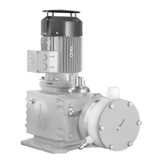
Metering pump
Hydro/ 4, HP4a
Please carefully read these operating instructions before use! · Do not discard!
The operator shall be liable for any damage caused by installation or operating errors!
Technical changes reserved.
984728
Original Operating Instructions (2006/42/EC)
BA HY 013 03/14 EN
Advertisement
Table of Contents


Need help?
Do you have a question about the Hydro/4 and is the answer not in the manual?
Questions and answers