Table of Contents
Advertisement
Quick Links
Operating instructions
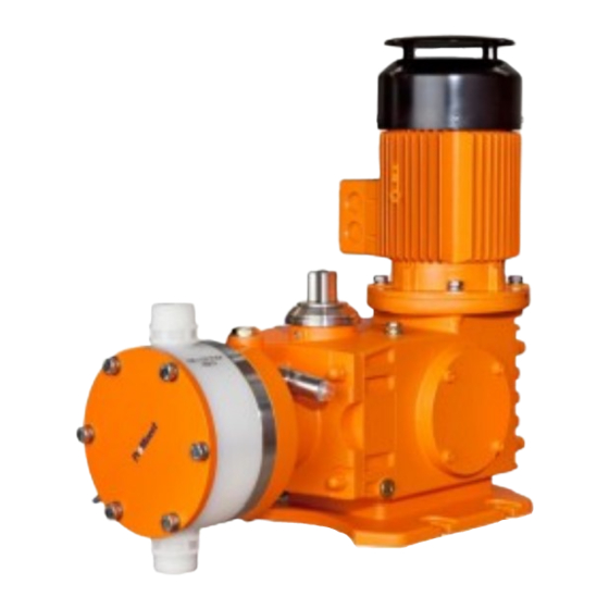
Metering pump
Hydro/ 4, HP4a
EN
Please carefully read these operating instructions before use. · Do not discard.
The operator shall be liable for any damage caused by installation or operating errors.
The latest version of the operating instructions are available on our homepage.
984728
Original operating instructions (2006/42/EC)
BA HY 019 12/18 EN
Advertisement
Table of Contents

Related Manuals for ProMinent Hydro/4 HP4a


Summary of Contents for ProMinent Hydro/4 HP4a
- Page 1 Operating instructions Metering pump Hydro/ 4, HP4a Please carefully read these operating instructions before use. · Do not discard. The operator shall be liable for any damage caused by installation or operating errors. The latest version of the operating instructions are available on our homepage. 984728 Original operating instructions (2006/42/EC) BA HY 019 12/18 EN...
- Page 2 Supplemental directives Supplementary information Read the following supplementary information in its entirety! Should you already know this information, you will benefit more from referring to the operating instructions. The following are highlighted separately in the document: Enumerated lists Fig. 1: Please read! Operating guidelines ð...
-
Page 3: Table Of Contents
Table of contents Table of contents Identity code..................5 Safety chapter................. 8 2.1 Safety information for ATEX designs........13 2.2 Explanation of the ATEX label..........25 Storage, transport and unpacking..........28 Overview of device / control elements........... 30 Functional description..............31 Assembly.................. - Page 4 Table of contents 14.5 Pressure switch..............87 14.6 General................87 Dimensional drawings..............89 Earthing drawing................102 EU Declaration of Conformity for Machinery....... 103 EU Declaration of Incorporation for Machinery......104 EU Declaration of Conformity for Machines ATEX HP4 without heating cartridge................105 EU Declaration of Conformity for Machines ATEX HP4 with heating cartridge................
-
Page 5: Identity Code
Dosing head design no valve spring (standard) With valve spring Hydraulic connector Standard threaded connector (in line with technical data) With DIN ISO flange With ANSI flange Design with ProMinent logo (standard) ® without ProMinent ® logo with ProMinent ®... - Page 6 Identity code HP4a Hydro/ 4, version a 3-phase, 230 V/400 V 50/60 Hz, 1.1 kW 3-phase, 230 V/400 V, 50 Hz, (Exe, Exde), 1.1 kW 3-phase, 265 V/440 V, 60 Hz, (Exe, Exde), 1.1 kW 3-phase variable speed stroke control motor, 230/400 V, 1.5 kW V(0) Variable speed motor with integrated Frequency converter 1-phase, 230 V, 50/60 Hz...
- Page 7 Identity code Tab. 1: * Type, power (at 50 Hz) Type Capacity Type Capacity Type Capacity Type Capacity 250130 160210 100330 070465 250190 160300 100480 070670 250250 160400 100635 070890 250350 160400 100800 071230 1230 250400 160625 101000 1000 071400 1400 Maximum back pressure for TTT, PPT and PCT material versions: 10 bar!
-
Page 8: Safety Chapter
Observe the general limitations with regard to viscosity limits, chem‐ ical resistance and density - see also the ProMinent Resistance List (in the Product Catalogue or at www.prominent.com)! All other uses or modifications are prohibited. - Page 9 Safety chapter You have a responsibility to adhere to the information contained in the operating instructions at the different phases of the unit's service life. You have a responsibility to observe the information contained in the operating instructions for the auxiliary equipment at the different phases of their respective service lives.
- Page 10 ProMinent or another authorised distribution partner. Service The Service department refers to service technicians, who have received proven training and have been authorised by ProMinent to work on the system. Safety information CAUTION!
- Page 11 – Take into account the resistance of the wetted mate‐ rials and the ProMinent Resistance List when selecting the feed chemical - see the ProMinent Product Catalogue or visit ProMinent. WARNING! Danger of injury to personnel and material damage The pump must only be opened at those points required to be opened by these operating instructions.
- Page 12 The use of untested third party parts can result in per‐ sonnel injuries and material damage. – Only fit parts to metering pumps, which have been tested and recommended by ProMinent. CAUTION! Danger from incorrectly operated or inadequately main‐ tained pumps Danger can arise from a poorly accessible pump due to incorrect operation and poor maintenance.
-
Page 13: Safety Information For Atex Designs
Safety chapter Adapt the operating instructions, if necessary Install the motor correctly Sound pressure level Sound pressure level LpA < 75 dB in accordance with EN ISO 20361:2010-10 at maximum stroke length, maximum stroke rate, maximum back pressure (water) 2.1 Safety information for ATEX designs This chapter lists all safety information for ATEX designs. - Page 14 Safety chapter Make sure that the person is familiar with the relevant body of standards and regulations and has worked in the field for at least one year. The person needs to have opportunities for an exchange of experiences. Specific requirements are placed on competent persons who perform tests on repaired devices/parts.
- Page 15 Safety chapter Ignition hazard Protective measures to be observed by the customer Mechanically generated sparks from the mechanism with Customer must monitor and maintain the pump in accord‐ low oil ance with the “Maintenance” chapter. Mechanically generated sparks from a faulty valve for the Customer must monitor the capacity.
- Page 16 Safety chapter Ignition hazard Protective measures to be observed by the customer Ignition hazard caused by bought-in heating cartridge with Refer to the documentation for the heating cartridge and protective temperature limiter the protective temperature limiter (electrical installation, maintenance, ...). Do not reprogram the protective temperature limiter.
- Page 17 Safety chapter WARNING! ATEX pumps in areas at risk from explosion – Metering pumps in areas at risk of explosion are provided, as a matter of course, with an appropriate safety relief valve on the outlet side of the metering pump (which is used to protect against excessive heating due to overloading and impact sparks caused by the breakage of power end parts trig‐...
- Page 18 Safety chapter WARNING! ATEX pumps in areas at risk from explosion – Make sure that a suitably competent person checks whether the appropriate installation information from the "Installation " chapter has been implemented correctly. – Make sure that a "recognised competent person" checks the electrical installation and in particular the intrinsically safe power circuits.
- Page 19 Safety chapter WARNING! The following applies in areas at risk from explosion: – Note the details of the type examination certificate PTB 00 ATEX 2048 X for the Namur sensor NJ1.5-8GM-N as well. WARNING! ATEX pumps in areas at risk from explosion –...
- Page 20 If re-painting, do not increase the layer thickness. – These measures are deemed to be minimum protec‐ tion measures by ProMinent. It is the duty of the operator to take appropriate measures to eliminate any further hazards known to him.
- Page 21 Safety chapter Electrically wire an additional potential equalisation cable from the poten‐ tial equalisation cables from this system cleanly and permanently to an electrically clean potential equalisation point, e.g. to a potential equalisa‐ tion bar on site. Potential equalisation of frame An earthing point for the customer is fitted on the frame.
- Page 22 Safety chapter Type iden‐ Feature Property tification Control output: programmable Certification: ATEX Electrical strength: 125 V AC relative to the housing Degrees of protection: II 2G Ex ia IIC T4 Modification number: 0.5 mm nozzle pressed in or integrated including accessories ZBE 08S-02 coupling socket M12x1, angled with 2 m wire, screened...
- Page 23 Other anomalies WARNING! Stop the pump immediately in the event of any anoma‐ lies when inspecting the pump and rectify them immedi‐ ately. ProMinent Service may be needed if required. Maintenance Interval Maintenance work Check whether the seals of the overpressure signalling system are OK and replace in case of doubt.
- Page 24 Safety chapter Installation height Data Value Unit Maximum installation height*: 1000 m above standard zero * We urgently advise you to contact a specialist for ATEX motors with higher intended installation heights! safety equipment Other safety equipment - ATEX labels WARNING! –...
-
Page 25: Explanation Of The Atex Label
Safety chapter Fit the motor correctly on the flange (qualified personnel). Observe the coupling operating instructions! WARNING! EX is relevant in areas at risk from explosion! With a claw coupling: The claw on the motor shaft must be fixed at the correct height, see corresponding figure and table. - Page 26 Safety chapter Ä Tab. 4 ‘Divi‐ Group IIC gas - refer, for example, to sion of gases into explosion groups and temperature classes’ on page 26 Ä Tab. 4 ‘Division of Group IIB gas - for example gases into explosion groups and temperature classes’ on page 26 Temperature class Max.
- Page 27 Safety chapter You should always consider the explosion group AND temperature class together: You are safe in areas at risk from explosion with all the gases listed in the table with equipment approved for explosion group IIC and temperature class T4. Equipment approved for explosion group IIB can also be used for explosion group IIA –...
-
Page 28: Storage, Transport And Unpacking
WARNING! The transporting of pumps which have been used with radioactive feed chemicals is forbidden! They will also not be accepted by ProMinent! WARNING! Only return the metering pump for repair in a cleaned state and with a flushed liquid end - refer to the chapter "Decommissioning"! - Page 29 Storage, transport and unpacking Storage Personnel: Technical personnel Plug the caps on the valves. Check whether the sealing screw is in place on the oil filler neck. Preferably place the pump standing vertically on a pallet and secure against falling over. Cover the pump with a tarpaulin cover - allowing rear ventilation.
-
Page 30: Overview Of Device / Control Elements
Overview of device / control elements Overview of device / control elements P_HY_0043_SW Fig. 3: Single head and double head version, Hydro/ 4 Power end Gear bleeding plug Hydraulic end Oil drain stopper Liquid End Oil drainage plug Stroke adjustment dial Stroke sensor (optional) Bleed valve Diaphragm rupture sensor... -
Page 31: Functional Description
Functional description Functional description Pump The metering pump is an oscillating diaphragm pump, the stroke length of which can be adjusted. Hydraulic end The hydraulic end has a bleed valve (2), a fixed pressure limitation valve (3) and optionally an overpressure signaller (1). The bleed valve (2) con‐ tinuously bleeds the hydraulic end. -
Page 32: Assembly
Assembly Assembly Compare the dimensions on the dimensional – drawing with those of the pump. Install the motor - with designs without motor Select a suitable motor - it must correspond to the data for one of the motors from the "Motor data" table - see Chapter "Technical data". - Page 33 Assembly P_HY_0060_SW Fig. 6: Correct height of the clutch claw on the motor shaft Tab. 5: Hydro HP4 Size Motor flange 143 / 145TC 2-1/8" 53,975 B5 / 250 Dimensions in mm - unless otherwise indicated. Base WARNING! Danger of electric shock If water or other electrically conducting liquids penetrate into the drive housing, in any other manner than via the pump's suction connection, an electric shock may occur.
- Page 34 Assembly Space requirement WARNING! Motor may overheat If the necessary cooling air supply is not guaranteed, the motor may overheat. In an area at risk from explosion, it could trigger an explosion. – Maintain sufficient clearance between the air intake opening and the walls.
- Page 35 Assembly Fastening Capacity too low Vibrations can disturb the liquid end valves. Secure the metering pump so that no vibrations can – occur. P_MOZ_0015_SW Fig. 10 Take the dimensions (m) for the fastening holes from the appro‐ priate dimensional or data sheets. Fix the pump base to the supporting floor with sufficient strong screws.
-
Page 36: Installation
Installation Installation CAUTION! Danger of injury to personnel and material damage Disregarding the technical data when installing may lead to personal injuries or damage to property. – Observe the technical data- refer to chapter "Tech‐ nical Data" and, where applicable, the operating instructions of the accessories. - Page 37 Installation WARNING! Warning of feed chemical reactions to water Feed chemicals that should not come into contact with water may react to residual water in the liquid end that may originate from works testing. – Blow the liquid end dry with compressed air through the suction connector.
- Page 38 They seal the connections between P_SI_0021 grooved pump valves and the grooved inserts from ProMinent - see Fig. 12. Fig. 12: Moulded composite seals with corrugated insert –...
- Page 39 Installation CAUTION! Warning of feed chemical spraying around PTFE seals, which have already been used / com‐ pressed, can no longer reliably seal a hydraulic connec‐ tion. – New, unused PTFE seals must always be used. P_SI_0022 Fig. 13: Elastomer flat seal for a smooth insert CAUTION! Danger due to incorrect use of the pressure relief valve...
-
Page 40: Basic Installation Notes
Installation 7.1.1 Basic installation notes Safety notes CAUTION! Danger resulting from rupturing hydraulic components Hydraulic components can rupture if the maximum per‐ missible operating pressure is exceeded. – Never allow the metering pump to run against a closed shut-off device. –... -
Page 41: Installation, Electrical
This can either be in the form of a declaration of conformity from the supplier (ProMinent) for the entire unit or, with the supply of individual compo‐ nents, with the operator's explosion protection docu‐... - Page 42 Installation WARNING! Danger of electric shock This pump is equipped with a protective earth conductor, to reduce the risk arising from an electric shock. – Connect the PE conductor to "earth" with a clean and permanent electrical connection. WARNING! Danger of electric shock A mains voltage may exist inside the motor or electrical ancillaries.
- Page 43 Installation WARNING! Only motors with a frequency converter: Danger of elec‐ tric shock On conducting parts of the motor with an integrated fre‐ quency converter and on the lines themselves, there remains a risk of an electric shock for 3 minutes after switching off the mains voltage.
- Page 44 Motor data sheets, special motors, special motor flanges, external fan, temperature monitoring Further information on motors can be found on our – website www.prominent.com. Motor data sheets can also be requested for the – motors. With motors other than those with identity code –...
- Page 45 Installation CAUTION! Danger resulting from unnoticed diaphragm rupture If the pump has been ordered with an electric diaphragm rupture sensor, it must also be electrically installed. – Install the enclosed diaphragm rupture sensor elec‐ trically to a suitable monitoring device. CAUTION! Additional damage with a ruptured diaphragm The diaphragm cannot be allowed to rupture fully if...
- Page 46 – Installation of the conduit – Control of seals – Permitted barriers – Configuration of r and I – Permissible connector plug WARNING! The pressure switch must not be reprogrammed without the written authorisation of ProMinent GmbH, Heidel‐ berg.
- Page 47 Installation Tab. 6: Plug pin assignments Cable colour Process connection brown white blue black Out 1 P_HY_0029_SW Fig. 16: Cable assignment grey Stroke sensor (optional) Connect the stroke sensor to a suitable monitoring device according to the details in the chapter "Technical Data" - also observe their technical data! The monitor / power supply installed by the customer must be able to evaluate the current variations of the Namur sensor for indicating...
-
Page 48: Start Up And Operation
Start up and operation Start up and operation Safety information WARNING! ATEX pumps in areas at risk from explosion – Make sure that a suitably competent person checks whether the appropriate installation information from the "Installation " chapter has been implemented correctly. - Page 49 Start up and operation WARNING! Only motors with a frequency converter: Danger of elec‐ tric shock The danger of electric shock remains for 3 minutes after the mains voltage has been switched off on conducting parts of the motor with an integrated frequency converter and on the lines themselves.
- Page 50 Start up and operation Test the diaphragm rupture sensor CAUTION! Feed chemical can escape unnoticed If the diaphragm rupture sensor does not stop the pump or no alarm is triggered, feed chemical can escape unnoticed. – Trigger the diaphragm rupture indicator - refer to the "Repair"...
-
Page 51: Bleeding The Liquid End
Start up and operation Use a safety relief valve CAUTION! Danger due to incorrect use of the safety relief valve The safety relief valve can only protect the motor and the gear, only against illegal positive pressure that is moni‐ tored by the metering pump itself. -
Page 52: Calibrate The Stroke Control Drive (Optional)
Fig. 17: Tapping the valve set disc 8.2 Calibrate the stroke control drive (optional) The stroke control drive is calibrated to the capacity ordered ex-factory. Please contact ProMinent in the event that you want the stroke control drive to be calibrated to another capacity. -
Page 53: Maintenance
"experienced personnel with the requisite knowledge". – These measures are deemed to be minimum protec‐ tion measures by ProMinent. It is the duty of the operator to take appropriate measures to eliminate any further hazards known to him. WARNING! ATEX pumps in areas at risk from explosion Static electricity can cause ignition sparks. - Page 54 Maintenance WARNING! Fire hazard with flammable media Only with flammable media: They can be ignited by oxygen. – The pump may not work if there is a mixture of feed chemical with oxygen in the liquid end. A specialist may need to take appropriate actions (using inert gas, ...).
- Page 55 Check the pump installation for: Leaks Abnormal noises or squeaks Abnormal temperatures Abnormal odours Abnormal vibrations Other anomalies WARNING! In the area at risk from explosion: stop the pump immediately and rectify these anomalies. ProMinent Service may be needed if required.
- Page 56 Open the inspection window on the flange to check. If the coupling is OK, the maintenance interval can be increased to 4000 hours. If the coupling is not clearly OK: Call ProMinent Service. ATEX pump only: Check the seals of the EDS 4448 pressure switch Technical personnel at regular intervals (depending on the climatic conditions and the feed chemical) in respect of their serviceability and replace if neces‐...
- Page 57 Maintenance Interval Maintenance work Personnel After approx. 4000 Only pumps with add-on power end or "without motor": Check the Technical personnel operating hours gear ring/DZ element of the ROTEX ® coupling as per their manual. Open the inspection window on the flange to check. After approx.
- Page 58 Maintenance P_HY_0059_SW Fill with hydraulic oil For the double-head versions, perform the following work simultaneously on both dosing heads. Set the stroke adjustment dial (1) to "100%" and screw out the bleed valve (2). Slowly fill hydraulic oil through the opening for the gearbox vent stopper (3) until the oil inspection window (3) is 1/3 covered.
-
Page 59: Repair
Repair Repair Safety information WARNING! ATEX pumps in areas at risk from explosion – Carry out a general check to ensure that the system is functioning properly, particularly the power end and bearings, by regular monitoring (for leaks, noises, temperatures, smell, etc.). WARNING! ATEX pumps in areas at risk from explosion Static electricity can cause ignition sparks. -
Page 60: Replacing The Diaphragm
Repair WARNING! Risk of fingers being crushed Under unfavourable conditions, the stroke axle or dis‐ placement body can cause crushing of the fingers. – Disconnect the pump from the mains power supply and ensure that it cannot be switched on again by unauthorised persons. - Page 61 Repair CAUTION! A diaphragm rupture may remain unnoticed Should the multi-layer diaphragm be handled incorrectly, the diaphragm rupture warning system may fail. – Take the multi-layer diaphragm from the packaging immediately before installing it. – Do not allow dirt to come into contact with the multi- layer diaphragm.
- Page 62 Repair P_HY_0033_SW Fig. 18 WARNING! Warning of injury to eyes The very strong spring (3) and the spring collar (5) on the diaphragm anchor (6) may spring away when loosening the safety collar (4). – To remove use the mounting aid (8)! –...
- Page 63 Repair Position the dosing head with the screws so that the suction con‐ nector is pointing downwards - diaphragm sensor must be at the bottom. First gently tighten the dosing head screws and then tighten cross‐ Ä Further information on page 63 . wise, tightening torque - Ä...
-
Page 64: Repairing The Diaphragm Rupture Sensor
Repair 10.2 Repairing the diaphragm rupture sensor WARNING! Feed chemical warning After a diaphragm rupture, additional feed chemical will be present in the diaphragm rupture sensor and the feed channel in the dosing head. – Protect yourself from the feed chemical if using haz‐ ardous or unknown feed chemicals. - Page 65 Repair If the diaphragm rupture sensor does not operate clearly and reli‐ ably, then a new diaphragm rupture sensor must be used without fail. ATEX version Checking the diaphragm rupture sensor When changing the diaphragm, unscrew the diaphragm rupture sensor from the dosing head. Check that the monitor does not indicate a diaphragm rupture: Using a blunt insulating probe (Ø...
-
Page 66: Calibrating The Dosing Rate
Repair 10.3 Calibrating the dosing rate It is only worth calibrating the dosing rate if you wish to carry out particu‐ larly precise metering at a completely different back pressure. The dosing rate of the hydraulic diaphragm metering pump is only dependent upon back pressure to a minimal extent. -
Page 67: Replacing Power End Bearings
Carefully tighten the screw (3) in the stroke adjustment dial and replace the cap (4). API versions only: Press the metal cap on to the stroke adjustment dial. 10.4 Replacing power end bearings Only allow ProMinent Service to replace the power end bearings! -
Page 68: Troubleshooting
Troubleshooting Troubleshooting Safety information WARNING! ATEX pumps in areas at risk from explosion – Generally ensure proper functioning (no leaks, unusual noises, high temperatures, unusual smell, vibrations, etc.) especially of the power end/drive and the bearings. – Do not allow the pump to heat up because of a lack of oil! With lubricated metering pumps, regularly check for the presence of lubricant, for example by checking... - Page 69 Troubleshooting WARNING! Danger of an electric shock Personnel working on electrical parts can be electro‐ cuted if all electrical lines carrying current have not been disconnected. – Disconnect the supply cable before working on the motor and prevent it from being reconnected acci‐ dentally.
- Page 70 The use of untested third party parts can result in per‐ sonnel injuries and material damage. – Only fit parts to metering pumps, which have been tested and recommended by ProMinent. CAUTION! Warning of feed chemical spraying around Feed chemical can spray out of the hydraulic compo‐...
- Page 71 The power end motor is very The discharge line is Rectify any constriction of the dis‐ Technical per‐ hot. seriously constricted. sonnel charge line. Have the safety relief valve checked. All other faults. Other causes. Call ProMinent Service.
-
Page 72: Decommissioning And Disposal
Decommissioning and disposal Decommissioning and disposal 12.1 Decommissioning WARNING! Fire hazard with flammable media Only with flammable media: They can be ignited by oxygen. – The pump may not work if there is a mixture of feed chemical with oxygen in the liquid end. A specialist may need to take appropriate actions (using inert gas, ...). -
Page 73: Disposal
Decommissioning and disposal CAUTION! Warning of feed chemical spraying around Feed chemical can spray out of the hydraulic compo‐ nents if they are manipulated or opened due to pressure in the liquid end and adjacent parts of the system. – Disconnect the pump from the mains power supply and ensure that it cannot be switched on again by unauthorised persons. - Page 74 Decommissioning and disposal WARNING! Danger due to spring tension There is a spring under high tension below the hydraulic cap under the diaphragm mounting plate. – Only remove the hydraulic cap in line with the "Hydro repair and configuration instructions." CAUTION! Environmental hazard due to hydraulic oil The pump contains hydraulic oil, which can cause...
-
Page 75: Technical Data
Technical data Technical data Only with "M - modified" design: WARNING! Risk of personal injuries Please observe the ”Supplement for modified version“ at the end of the chapter! It replaces and supplements the technical data! 13.1 Performance data HP4a with 50 Hz operation Type Minimum pump capacity at maximum back Maximum... -
Page 76: Metering Reproducibility
Technical data The suction lift / suction pressure applies to filled suction lines and filled liquid end - when installed correctly. HP4a with 60 Hz operation Type Minimum pump capacity at maximum back Maximum suction lift Permis‐ Connector size pressure stroke rate sible pri‐... -
Page 77: Viscosity
Technical data 13.3 Viscosity The liquid ends are generally suitable for the following viscosity ranges: Design Range Unit no valve springs 0 ... 200 mPas with valve springs 200 ... 500 mPas 13.4 Weight For pumps with a standard motor. Hydro HP4 SST Design Weight approx. - Page 78 Technical data Data Value Unit Ambient temperature in operation -10 ... +40 °C ("Standard" version, for drive): Ambient temperature in operation ("Low -25 ... +40 °C temperature" version, for drive): Ambient temperature in operation ("Low -20 ... +40 °C temperature Zone 2" version, for drive): * Only with heating heating cartridge PPT liquid end Data...
-
Page 79: Air Humidity
Technical data Data Value Unit Minimum temperature "Standard" -10 °C Minimum temperature "Low temperature -20 °C Zone 2" HCT liquid end Data Value Unit Max. temperature, long-term at max. oper‐ 90 °C ating pressure Max. temperature, for 15 min at max. 2 bar 120 °C Minimum temperature "Standard"... -
Page 80: Housing Degree Of Protection
Technical data * with standard pumps: Fit at higher installation heights at your own risk. with ATEX pumps: We urgently advise that you contact a specialist for ATEX motors at higher installation heights! 13.7 Housing degree of protection Data Value Protection against contact and moisture* IP 55 *according to DIN VDE 470 (EN IEC 60529) -
Page 81: Diaphragm Rupture Sensor
Technical data Motor data sheets, special motors, special motor flanges, external fan, temperature monitoring Motor data sheets can be requested for the motors. – With motors other than those with identity code – specifications "S", "M" or "N": Pay special attention to the operating instructions for the motors. -
Page 82: Pressure Limitation Valve (Hp4)
Technical data Cable colour Polarity blue brown Install the sensor according to the chapter "Installation, electrical". Refer to its documentation. The sensor is of type NJ1.5-8GM-N. 13.10 Pressure limitation valve (HP4) Pressure stage 7 bar 10 bar 16 bar 25 bar Opening pressure 14 bar 18 bar... -
Page 83: Heating Cartridge
Technical data * Ri ~ 1 kΩ Cable colour Polarity blue brown Install the sensor according to the chapter "Installation, electrical". Refer to its documentation. Sensor name: NJ1.5-8GM-N. 13.13 Heating cartridge Technical data - see enclosed operating instructions: "ELMESS operating instructions liquid heater type NAHF11 ...; HRHF11". 13.14 Filling volumes 13.14.1 Hydraulic oil... -
Page 84: Supplement For Modified Versions
Technical data 13.16 Supplement for modified versions (With Identcode specification "Version": "M" - "modified") Technical data Technical data of pumps in the modified version can deviate from those of the standard pumps. They can be queried by stating the details of the serial number. -
Page 85: Ordering Information
Ordering information Ordering information 14.1 Exploded view drawing P_HY_0017_SW Fig. 23: Exploded view of Hydro liquid end Numbered positions = PVT set of spare parts - range for supply. Technical changes reserved. Seals (Set) Suction connection assy. Valve balls Diaphragm Pressure connection assy. - Page 86 Ordering information Spare parts kits Hydro/ 4 for types: 250130, 250190, 250250, 250350, 250400: for liquid end Material version Order no. FMH 400 - DN 25 1043763 PVT with valve 1023057 1040812 SST with valve 1040813 1040860 HCT with valve 1022716 ...
-
Page 87: Diaphragms
Ordering information 14.3 Diaphragms Metering diaphragm PTFE / 1.4404 for liquid end Pump type Order no. FMH 400 250130, 250190, 250250, 250350, 250400 1040808 FMH 625 160210, 160300, 160400, 160550, 160625 1040809 FMH 1000 100330, 100480, 100635, 100880, 101000 1040810 FMH 1400 0704650, 070670, 070890, 071230, 071400 1040811... - Page 88 Ordering information Manufacturer Name Viscosity class Order no. Standard Mobil Mobilube 1 SHC * 75W - 90 1006010** * or comparative hydraulic oil ** 1 L Manufacturer Name Viscosity class Order no. Food Mobil SHC Cibus * 1007664** * or comparative hydraulic oil ** 1 L Required amount of oil Supplied...
-
Page 89: Dimensional Drawings
Dimensional drawings Dimensional drawings Compare the dimensions on the dimension sheet – and pump. All dimensions are in mm. – Hydro HP4 dimensions sheet (HP4a single head pump) Ø12 ØF P_HY_0038_SW Fig. 24: Diagram is not strictly binding. Liquid end Type 250130 160210... - Page 90 Dimensional drawings Standard Exe motor Exde motor Motor with fre‐ Exde motors Motor, control‐ motor quency con‐ with a frequency lable verter converter Hydro HP4 dimensions sheet (HP4a double-head pump) P_HY_0049_SW 61_02-101_00_33-7Ax05_B2 Fig. 25: Diagram is not strictly binding. Liquid end Type 250130 160210...
- Page 91 Dimensional drawings Standard Exe motor Exde motor Motor with fre‐ Exde motors Motor, control‐ motor quency con‐ with a frequency lable verter converter Dimension sheet Hydro HP4 (duplex single head pump) P_HY_0050_SW 61_02-101_00_33-7Ax05_B3 Fig. 26: Diagram is not strictly binding. Liquid end Type 250130...
- Page 92 Dimensional drawings Standard Exe motor Exde motor Motor with fre‐ Exde frequency Motor, control‐ motor quency con‐ converter motor lable verter Hydro HP4 dimensions sheet (HP4a duplex double-head pump) P_HY_0051_SW 61_02-101_00_33-7Ax05_B4 Fig. 27: Diagram is not strictly binding. Liquid end Type 250130 160210...
- Page 93 Dimensional drawings Standard Exe motor Exde motor Motor with fre‐ Exde frequency Motor, control‐ motor quency con‐ converter motor lable verter...
- Page 94 Dimensional drawings Hydro HP4 dimensions sheet (HP4a tri‐ plex pump) P_HY_0052_SW 61_02-101_00_33-7Ax05_B5 Fig. 28: Diagram is not strictly binding.
- Page 95 Dimensional drawings Liquid end Type 250130 160210 100330 070465 250190 160300 100480 070670 250250 160400 100635 070890 250350 160550 100880 071230 250400 160625 101000 071400 SS/HC PV/TT SS/HC/PV SS/HC/PV SS/HC/PV SS/HC PV/TT SS/HC/PV SS/HC/PV SS/HC/PV SS/HC/PV DN25, G1 1/2 DN25, G1 1/2 DN32, G2 DN40, G2 1/4 Standard...
- Page 96 Dimensional drawings Hydro HP4 dimensions sheet (HP4a with ATEX FC) P_HY_0053_SW 61_02-101_00_33-7Ax05_B6a Fig. 29: Diagram is not strictly binding. Hydro HP4 dimensions sheet (HP4a without motor with motor flange) P_HY_0054_SW 61_02-101_00_33-7Ax05_B6b Fig. 30: Diagram is not strictly binding.
- Page 97 Dimensional drawings Size Motor flange 6,575" 5,875" 4.5" 0,433" 0,875" 2-1/8" 0,197" 3/16" 0,964" 14.21" (H7) 145TC 149.23 22:23 53,975 4.7625 24.49 114.3 (H7) B5/250 31.3 (H7) Hydro HP4 dimensions sheet (HP4a without motor without motor flange) P_HY_0058_SW 61_02-101_00_33-7Ax05_B6c Fig. 31: Diagram is not strictly binding.
- Page 98 Dimensional drawings Hydro HP4 dimensions sheet (HP4a single pump with servomotor) P_HY_0056_SW 61_02-101_00_33-7Ax05_B7a Fig. 32: Diagram is not strictly binding. Liquid end Type 250130 160210 100330 070465 250190 160300 100480 070670 250250 160400 100635 070890 250350 160550 100880 071230 250400 160625 101000 071400...
- Page 99 Dimensional drawings Hydro HP4 dimensions sheet (HP4a double-head pump with servomotor) P_HY_0057_SW 61_02-101_00_33-7Ax05_B7b Fig. 33: Diagram is not strictly binding. Liquid end Type 250130 160210 100330 070465 250190 160300 100480 070670 250250 160400 100635 070890 250350 160550 100880 071230 250400 160625 101000 071400...
- Page 100 Dimensional drawings Liquid end Type 250130 160210 100330 070465 250190 160300 100480 070670 250250 160400 100635 070890 250350 160550 100880 071230 250400 160625 101000 071400 SS/HC/PV SS/HC/PV SS/HC PV/TT SS/HC/PV SS/HC/PV SS/HC/PV Valve DN25, G1 1/2 DN25, G1 1/2 DN32, G2 DN40, G2 1/4 Standard Exe motor...
- Page 101 Dimensional drawings Hydro HP4 dimensions sheet (HP4a with heating cartridge) ATEX P_HY_0055_SW 61_02-101_00_33-7Ax05_B9.svg Fig. 34: Diagram is not strictly binding.
-
Page 102: Earthing Drawing
Earthing drawing Earthing drawing Simplex single head Hydro HP4 with actuator and heating cartridge P_HY_0044_SW Motor Heating cartridge (optional) Actuator... -
Page 103: Eu Declaration Of Conformity For Machinery
Machinery Directive 2006/42/EC Harmonised standards applied, in EN ISO 12100:2010, EN 809:1998 + A1:2009 + AC:2010 particular: EN 61000-6-2:2005, EN 61000-6-4:2007 + A1:2011 EN 60204-1:2006 + A1:2009 Date: 20.04.2016 You can download the Declaration of Conformity at www.prominent.com. -
Page 104: Eu Declaration Of Incorporation For Machinery
In accordance with DIRECTIVE 2006/42/EC OF THE EUROPEAN PAR‐ LIAMENT AND OF THE COUNCIL, Appendix I, BASIC HEALTH AND SAFETY REQUIREMENTS, section 1.7.4.2. C. ProMinent GmbH Im Schuhmachergewann 5 - 11 D - 69123 Heidelberg, Germany, hereby declare that the product specified in the following, complies with... -
Page 105: Eu Declaration Of Conformity For Machines Atex Hp4 Without Heating Cartridge
II 2G Ex h IIB T4 Gc X for $ = "2" and % = "1", "2", "A", "B", "C", "D" X: maximum medium temperature 90 °C Ambient temperature -10 … +40 °C Date: 16.11.2018 You can download the Declaration of Conformity at www.prominent.com. -
Page 106: Eu Declaration Of Conformity For Machines Atex Hp4 With Heating Cartridge
II 3G Ex h IIB T3 Gc X for $ = "1" system: II 3G Ex h IIB T4 Gc X for $ = "2" X: maximum medium temperature 90 °C Date: 16.11.2018 You can download the Declaration of Conformity at www.prominent.com. -
Page 107: Ec Declaration Of Incorporation For Machines Atex Hp4 Without Heating Cartridge
In accordance with DIRECTIVE 2006/42/EC OF THE EUROPEAN PAR‐ LIAMENT AND OF THE COUNCIL, Appendix I, BASIC HEALTH AND SAFETY REQUIREMENTS, section 1.7.4.2. C. ProMinent GmbH Im Schuhmachergewann 5 - 11 D - 69123 Heidelberg, Germany, hereby declare that the product specified below complies with the relevant basic health and safety requirements of the EC Directive on the basis of its functional concept and design and in the version marketed by us. -
Page 108: Ec Declaration Of Incorporation For Machines Atex Hp4 With Heating Cartridge
In accordance with DIRECTIVE 2006/42/EC OF THE EUROPEAN PAR‐ LIAMENT AND OF THE COUNCIL, Appendix I, BASIC HEALTH AND SAFETY REQUIREMENTS, section 1.7.4.2. C. ProMinent GmbH Im Schuhmachergewann 5 - 11 D - 69123 Heidelberg, Germany, hereby declare that the product specified below complies with the relevant basic health and safety requirements of the EC Directive on the basis of its functional concept and design and in the version marketed by us. -
Page 109: Diagrams For Adjusting The Capacity
Diagrams for adjusting the capacity Diagrams for adjusting the capacity Hydro/ 4 HP4a H C (l/h) C (l/h) 250400 160625 250350 160550 250250 160400 250190 160300 250130 160210 s [%] s [%] C (l/h) C (l/h) 250400 160625 160550 250350 160400 250250 160300... - Page 112 ProMinent GmbH Im Schuhmachergewann 5-11 69123 Heidelberg Germany Telephone: ++49 6221 842-0 Fax: ++49 6221 842-419 Email: info@prominent.com Internet: www.prominent.com 984728, 3, en_GB © 2010...
Need help?
Do you have a question about the Hydro/4 HP4a and is the answer not in the manual?
Questions and answers