Bosch Rexroth IndraControl S67 Manual
Digital module high speed 4 inputs/outputs – 0.2 a (4×m12)
Hide thumbs
Also See for Rexroth IndraControl S67:
- Manual (96 pages) ,
- Application description (88 pages) ,
- Application description (142 pages)

Related Manuals for Bosch Rexroth IndraControl S67


Summary of Contents for Bosch Rexroth IndraControl S67
- Page 1 The Drive & Control Company Rexroth IndraControl S67 Digital Module High Speed 4 Inputs/Outputs – 0.2 A (4×M12) Application Description Edition 02 R911342202...
- Page 2 © Bosch Rexroth AG 2014 This document, as well as the data, specifications and other information set forth in it, are the exclusive property of Bosch Rexroth AG. It may not be re‐ produced or given to third parties without its consent.
-
Page 3: Table Of Contents
DOK-CONTRL-S67DIO4M12H-AP02-EN-P Bosch Rexroth AG I/79 Rexroth IndraControl S67 Digital Module High Speed 4 Inputs/Outputs – 0.2 A (84×M12) Table of Contents Table of Contents Page About this Documentation....................5 General Information..........................5 Scope..............................5 Validity of the Documentation......................... 6 Structuring the Documentation....................... 7 Terms and Abbreviations........................ - Page 4 II/79 Bosch Rexroth AG DOK-CONTRL-S67DIO4M12H-AP02-EN-P Rexroth IndraControl S67 Digital Module High Speed 4 Inputs/Outputs – 0.2 A (84×M12) Table of Contents Page 4.9.15 Electrical Isolation..........................24 4.9.16 Standards and Approvals........................25 Mounting the Module....................27 General Information..........................27 Mounting Notes............................. 27 Required Tools and Accessories for Mounting..................
- Page 5 DOK-CONTRL-S67DIO4M12H-AP02-EN-P Bosch Rexroth AG III/79 Rexroth IndraControl S67 Digital Module High Speed 4 Inputs/Outputs – 0.2 A (84×M12) Table of Contents Page DI Operation Mode..........................53 9.3.1 Input Data............................53 9.3.2 Output Data............................54 DIO Operation Mode..........................55 9.4.1 Input Data............................55 9.4.2...
- Page 6 IV/79 Bosch Rexroth AG DOK-CONTRL-S67DIO4M12H-AP02-EN-P Rexroth IndraControl S67 Digital Module High Speed 4 Inputs/Outputs – 0.2 A (84×M12) Table of Contents Page Appendix........................73 14.1 Diagnostic Information.......................... 73 Service and support..................... 75 Index..........................77...
-
Page 7: About This Documentation
DOK-CONTRL-S67DIO4M12H-AP02-EN-P Bosch Rexroth AG 5/79 Rexroth IndraControl S67 Digital Module High Speed 4 Inputs/Outputs – 0.2 A (84×M12) About this Documentation About this Documentation General Information Read this chapter thoroughly before using the application description. Scope The present documentation applies to the digital input and output module S67-DIO4-HS-M12 of the IndraControl S67 series. -
Page 8: Validity Of The Documentation
6/79 Bosch Rexroth AG DOK-CONTRL-S67DIO4M12H-AP02-EN-P Rexroth IndraControl S67 Digital Module High Speed 4 Inputs/Outputs – 0.2 A (84×M12) About this Documentation Document Title Parts num‐ Application De‐ Rexroth IndraControl S67 Digital Module High R911342198 scription Speed 8 Inputs (4×M12) Application De‐... -
Page 9: Structuring The Documentation
DOK-CONTRL-S67DIO4M12H-AP02-EN-P Bosch Rexroth AG 7/79 Rexroth IndraControl S67 Digital Module High Speed 4 Inputs/Outputs – 0.2 A (84×M12) About this Documentation Mounting Product Selection Engineering Commissioning Operation Decommissioning phases (assembly/installation) Presales Aftersales Design engineer Mechanic/ electrician Programmer Programmer Commissioning engineer... -
Page 10: Terms And Abbreviations
8/79 Bosch Rexroth AG DOK-CONTRL-S67DIO4M12H-AP02-EN-P Rexroth IndraControl S67 Digital Module High Speed 4 Inputs/Outputs – 0.2 A (84×M12) About this Documentation For diagnostic information, refer to chapter 14 "Appendix" on page For information on the customer service help desk of Bosch Rexroth, refer to chapter 15 "Service and support"... -
Page 11: Important Instructions On Use
DOK-CONTRL-S67DIO4M12H-AP02-EN-P Bosch Rexroth AG 9/79 Rexroth IndraControl S67 Digital Module High Speed 4 Inputs/Outputs – 0.2 A (84×M12) Important Instructions on Use Important Instructions on Use Intended Use 2.1.1 Introduction The Rexroth products represent state-of-the-art developments and manufac‐ turing. The products are tested prior to delivery to ensure operating safety and reliability. -
Page 12: Unintended Use
10/79 Bosch Rexroth AG DOK-CONTRL-S67DIO4M12H-AP02-EN-P Rexroth IndraControl S67 Digital Module High Speed 4 Inputs/Outputs – 0.2 A (84×M12) Important Instructions on Use Field bus coupler Technical index Operation modes S67-PB-BK-DI8-M8 DI, DO, DIO DIO + counter S67-PN-BK-DI8-M8 S67-ET-BK-DI8-M8 S67-S3-BK-DI8-M8 Tab. 2-1:... -
Page 13: Using The Safety Instructions
DOK-CONTRL-S67DIO4M12H-AP02-EN-P Bosch Rexroth AG 11/79 Rexroth IndraControl S67 Digital Module High Speed 4 Inputs/Outputs – 0.2 A (84×M12) Using the Safety Instructions Using the Safety Instructions Structure of the Safety Instructions The safety instructions are structured as follows: Consequences and... -
Page 14: Symbols Used
12/79 Bosch Rexroth AG DOK-CONTRL-S67DIO4M12H-AP02-EN-P Rexroth IndraControl S67 Digital Module High Speed 4 Inputs/Outputs – 0.2 A (84×M12) Using the Safety Instructions Symbols Used Pointers are displayed as follows: This is a note. Tips are displayed as follows: This is a tip. -
Page 15: Device Description
DOK-CONTRL-S67DIO4M12H-AP02-EN-P Bosch Rexroth AG 13/79 Rexroth IndraControl S67 Digital Module High Speed 4 Inputs/Outputs – 0.2 A (84×M12) Device Description Device Description General Information The digital input and output module S67-DIO4-HS-M12 inputs or outputs bi‐ nary signals of sensors and actuators with short response times. The module is provided with fast high-speed inputs and outputs and thus especially suita‐... -
Page 16: Connections
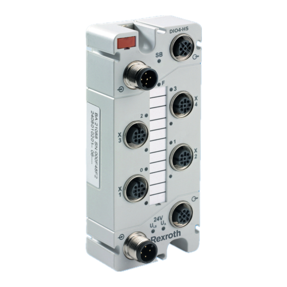
14/79 Bosch Rexroth AG DOK-CONTRL-S67DIO4M12H-AP02-EN-P Rexroth IndraControl S67 Digital Module High Speed 4 Inputs/Outputs – 0.2 A (84×M12) Device Description Connections DIO4-HS Fig. 4-1: ID of the module connections Position Description Function S-BUS input To transmit data of the previous... -
Page 17: Labeling Options And Mounting
DOK-CONTRL-S67DIO4M12H-AP02-EN-P Bosch Rexroth AG 15/79 Rexroth IndraControl S67 Digital Module High Speed 4 Inputs/Outputs – 0.2 A (84×M12) Device Description Labeling Options and Mounting DIO4-HS Fig. 4-2: Identifying options for labeling and mounting Position Description Function Module labeling plate To identify the module in a field bus node Mounting holes Mounting and grounding the module us‐... -
Page 18: Display Elements
16/79 Bosch Rexroth AG DOK-CONTRL-S67DIO4M12H-AP02-EN-P Rexroth IndraControl S67 Digital Module High Speed 4 Inputs/Outputs – 0.2 A (84×M12) Device Description Display Elements DIO4-HS Fig. 4-3: Identifying module LEDs Position Color Meaning Green/red/ S-BUS status orange Diagnostic information 0 to 3 Yellow/red Yellow: Status message of 4 chan‐... -
Page 19: Labeling And Symbols At Rear Side
DOK-CONTRL-S67DIO4M12H-AP02-EN-P Bosch Rexroth AG 17/79 Rexroth IndraControl S67 Digital Module High Speed 4 Inputs/Outputs – 0.2 A (84×M12) Device Description Labeling and Symbols at Rear Side Bosch Rexroth AG Bgm.-Dr.-Nebel-Str. 2 97816 Lohr, Germany Made in Germany S67-DIO4-HS-M12 U : DC 24V... -
Page 20: Schematic Diagram
18/79 Bosch Rexroth AG DOK-CONTRL-S67DIO4M12H-AP02-EN-P Rexroth IndraControl S67 Digital Module High Speed 4 Inputs/Outputs – 0.2 A (84×M12) Device Description ① Type code ② Parts number ③ Technical index ④ Date of manufacture ⑤ Serial number Fig. 4-5: Type plate... -
Page 21: Dimensions
DOK-CONTRL-S67DIO4M12H-AP02-EN-P Bosch Rexroth AG 19/79 Rexroth IndraControl S67 Digital Module High Speed 4 Inputs/Outputs – 0.2 A (84×M12) Device Description Dimensions DIO4-HS 18,25 34,75 37,75 Fig. 4-7: Module dimensions in millimeters Technical Data 4.9.1 Device Data Dimensions (mm) W × H × D 50 ×... -
Page 22: Communication
20/79 Bosch Rexroth AG DOK-CONTRL-S67DIO4M12H-AP02-EN-P Rexroth IndraControl S67 Digital Module High Speed 4 Inputs/Outputs – 0.2 A (84×M12) Device Description Supply voltages Logic voltage U 24 V DC (-25 % … +30 %) 24 V DC (-25 % … +30 %) Sensor/actuator voltage U ②... -
Page 23: Input Characteristic Curve
DOK-CONTRL-S67DIO4M12H-AP02-EN-P Bosch Rexroth AG 21/79 Rexroth IndraControl S67 Digital Module High Speed 4 Inputs/Outputs – 0.2 A (84×M12) Device Description 4.9.5 Input Characteristic Curve Input voltage U Typical input current 0 mA 2.0 mA 15 V 2.5 mA 24 V 2.9 mA... -
Page 24: Counters (Parameterizable)
22/79 Bosch Rexroth AG DOK-CONTRL-S67DIO4M12H-AP02-EN-P Rexroth IndraControl S67 Digital Module High Speed 4 Inputs/Outputs – 0.2 A (84×M12) Device Description Interrupting the S-BUS 0 V status Supply voltage under rated voltage toler‐ 0 V status ance Disconnection of supply voltage... -
Page 25: Parameterizable Counter Functions
DOK-CONTRL-S67DIO4M12H-AP02-EN-P Bosch Rexroth AG 23/79 Rexroth IndraControl S67 Digital Module High Speed 4 Inputs/Outputs – 0.2 A (84×M12) Device Description 4.9.11 Parameterizable Counter Functions Operation mode: Counter mode - Event counter - Gate time counter - Pulse duration measurement Gate time basis - 1.0 ms... -
Page 26: Diagnostics
24/79 Bosch Rexroth AG DOK-CONTRL-S67DIO4M12H-AP02-EN-P Rexroth IndraControl S67 Digital Module High Speed 4 Inputs/Outputs – 0.2 A (84×M12) Device Description - Locked Counter reset ① - Released (if limit value violation) - Locked Limit value status toggle ① - Released Only provided when using DTM ①... -
Page 27: Standards And Approvals
DOK-CONTRL-S67DIO4M12H-AP02-EN-P Bosch Rexroth AG 25/79 Rexroth IndraControl S67 Digital Module High Speed 4 Inputs/Outputs – 0.2 A (84×M12) Device Description 4.9.16 Standards and Approvals UL/CSA UL 508 (Industrial Control Equipment) C22.2 No. 14-95 (CSA) UL file no. E210730 Conformity marking Tab. - Page 28 26/79 Bosch Rexroth AG DOK-CONTRL-S67DIO4M12H-AP02-EN-P Rexroth IndraControl S67 Digital Module High Speed 4 Inputs/Outputs – 0.2 A (84×M12)
-
Page 29: Mounting The Module
DOK-CONTRL-S67DIO4M12H-AP02-EN-P Bosch Rexroth AG 27/79 Rexroth IndraControl S67 Digital Module High Speed 4 Inputs/Outputs – 0.2 A (84×M12) Mounting the Module Mounting the Module General Information The S67-DIO4-HS-M12 module can be fastened directly to the system using screws. It can also be mounted on a mounting rail using an adapter or fas‐... -
Page 30: Direct Mounting To The System
28/79 Bosch Rexroth AG DOK-CONTRL-S67DIO4M12H-AP02-EN-P Rexroth IndraControl S67 Digital Module High Speed 4 Inputs/Outputs – 0.2 A (84×M12) Mounting the Module ● Spacer (optional) Two M4x12 screws are required for direct mounting of the S67-DIO4-HS-M12 module. The length of the screw shaft is to be selected according to the fas‐... -
Page 31: Fastening The Module With Mounting Rail Adapter To A Mounting Rail
DOK-CONTRL-S67DIO4M12H-AP02-EN-P Bosch Rexroth AG 29/79 Rexroth IndraControl S67 Digital Module High Speed 4 Inputs/Outputs – 0.2 A (84×M12) Mounting the Module Fig. 5-2: Mounting on the mounting rail adapter 5.5.2 Fastening the Module with Mounting Rail Adapter to a Mounting Rail In order to keep a clear representation, the mounting rail adapter in the figure below is shown without the S67-DIO4-HS-M12 module. -
Page 32: Mounting On Profile Rail (Only With Bosch Rexroth Accessories)
30/79 Bosch Rexroth AG DOK-CONTRL-S67DIO4M12H-AP02-EN-P Rexroth IndraControl S67 Digital Module High Speed 4 Inputs/Outputs – 0.2 A (84×M12) Mounting the Module Fig. 5-3: Mounting the mounting rail adapter Mounting on Profile Rail (only with Bosch Rexroth Accesso‐ ries) 5.6.1 Fastening Profile Adapter on the Module... -
Page 33: Fastening The Module With Profile Adapter On Profile Rail
DOK-CONTRL-S67DIO4M12H-AP02-EN-P Bosch Rexroth AG 31/79 Rexroth IndraControl S67 Digital Module High Speed 4 Inputs/Outputs – 0.2 A (84×M12) Mounting the Module 5.6.2 Fastening the Module with Profile Adapter on Profile Rail To fasten the S67-DIO4-HS-M12 module to a profile rail of the system, two nuts are required with one screw each (length of screw threads must be com‐... -
Page 34: Mounting The Spacer In Case Of Compact Arrangement
32/79 Bosch Rexroth AG DOK-CONTRL-S67DIO4M12H-AP02-EN-P Rexroth IndraControl S67 Digital Module High Speed 4 Inputs/Outputs – 0.2 A (84×M12) Mounting the Module Mounting the Spacer in Case of Compact Arrangement By using the spacer, a sufficient mounting distance can be achieved when di‐... - Page 35 DOK-CONTRL-S67DIO4M12H-AP02-EN-P Bosch Rexroth AG 33/79 Rexroth IndraControl S67 Digital Module High Speed 4 Inputs/Outputs – 0.2 A (84×M12) Mounting the Module DIO4-HS DIO4-HS Fig. 5-7: Attaching a further module with spacer...
- Page 36 34/79 Bosch Rexroth AG DOK-CONTRL-S67DIO4M12H-AP02-EN-P Rexroth IndraControl S67 Digital Module High Speed 4 Inputs/Outputs – 0.2 A (84×M12)
-
Page 37: Connecting Data And Supply Cable
DOK-CONTRL-S67DIO4M12H-AP02-EN-P Bosch Rexroth AG 35/79 Rexroth IndraControl S67 Digital Module High Speed 4 Inputs/Outputs – 0.2 A (84×M12) Connecting Data and Supply Cable Connecting Data and Supply Cable Notes Voltage! WARNING Operate the IndraControl S67 components exclusively with DC 24 V PELV (Protective Extra Low Voltage) or SELV (Safety Extra Low Voltage) voltage sources. -
Page 38: Required Accessories
36/79 Bosch Rexroth AG DOK-CONTRL-S67DIO4M12H-AP02-EN-P Rexroth IndraControl S67 Digital Module High Speed 4 Inputs/Outputs – 0.2 A (84×M12) Connecting Data and Supply Cable Required Accessories The Bosch Rexroth accessory components listed below are required for con‐ necting the data and supply cable. The associated order numbers are listed chapter 13 "Accessories"... -
Page 39: Supply Cable Connection
DOK-CONTRL-S67DIO4M12H-AP02-EN-P Bosch Rexroth AG 37/79 Rexroth IndraControl S67 Digital Module High Speed 4 Inputs/Outputs – 0.2 A (84×M12) Connecting Data and Supply Cable DIO4-HS DIO4-HS DIO4-HS 12| RES 12| RES 11| B/E 11| B/E 10| R/S 10| R/S 7| 2... - Page 40 38/79 Bosch Rexroth AG DOK-CONTRL-S67DIO4M12H-AP02-EN-P Rexroth IndraControl S67 Digital Module High Speed 4 Inputs/Outputs – 0.2 A (84×M12) Connecting Data and Supply Cable Fig. 6-2: Supply cable assembled on one end The highest current carrying capacity of the NOTICE supply contacts is 4 A! Always observe the maximum current carrying capacity per supply line (U ) as well as the total current consumption for all IndraControl S67 compo‐...
-
Page 41: Connecting The Sensor/Actuator Cable
DOK-CONTRL-S67DIO4M12H-AP02-EN-P Bosch Rexroth AG 39/79 Rexroth IndraControl S67 Digital Module High Speed 4 Inputs/Outputs – 0.2 A (84×M12) Connecting Data and Supply Cable DIO4-HS DIO4-HS 12| RES 11| B/E 10| R/S 7| 2 6| 2 5| 2 4| 2 3| 2... - Page 42 40/79 Bosch Rexroth AG DOK-CONTRL-S67DIO4M12H-AP02-EN-P Rexroth IndraControl S67 Digital Module High Speed 4 Inputs/Outputs – 0.2 A (84×M12) Connecting Data and Supply Cable The sensor's/actuator's power consumption NOTICE must not exceed 1 A! Please note that the combined power consumption of all connected sensors/ actuators must not exceed 1 A.
-
Page 43: Commissioning
DOK-CONTRL-S67DIO4M12H-AP02-EN-P Bosch Rexroth AG 41/79 Rexroth IndraControl S67 Digital Module High Speed 4 Inputs/Outputs – 0.2 A (84×M12) Commissioning Commissioning General Information Exposed connections! NOTICE If connections have not been closed with protective caps, liquid or dirt can penetrate the S67-DIO4-HS-M12 and destroy the module. Protect all non-re‐... - Page 44 42/79 Bosch Rexroth AG DOK-CONTRL-S67DIO4M12H-AP02-EN-P Rexroth IndraControl S67 Digital Module High Speed 4 Inputs/Outputs – 0.2 A (84×M12)
-
Page 45: Parameterization
DOK-CONTRL-S67DIO4M12H-AP02-EN-P Bosch Rexroth AG 43/79 Rexroth IndraControl S67 Digital Module High Speed 4 Inputs/Outputs – 0.2 A (84×M12) Parameterization Parameterization General Information According to the field bus type, only specified parameters are available for parameterization. For further information, refer to respective field bus coupler manuals. -
Page 46: Input And Output Parameters
44/79 Bosch Rexroth AG DOK-CONTRL-S67DIO4M12H-AP02-EN-P Rexroth IndraControl S67 Digital Module High Speed 4 Inputs/Outputs – 0.2 A (84×M12) Parameterization Global diagnostics Description Undervoltage at WARNING Disabling the outputs. In case of an undervoltage of U and/or U , the module out‐... -
Page 47: Operation Mode "Do Module
DOK-CONTRL-S67DIO4M12H-AP02-EN-P Bosch Rexroth AG 45/79 Rexroth IndraControl S67 Digital Module High Speed 4 Inputs/Outputs – 0.2 A (84×M12) Parameterization Parameter Description Operation mode DO module: Operated as digital output module DI module: Operated as digital input module DIO module: Operated as digital input and output module This is the state upon delivery. -
Page 48: Operation Mode "Di Module
46/79 Bosch Rexroth AG DOK-CONTRL-S67DIO4M12H-AP02-EN-P Rexroth IndraControl S67 Digital Module High Speed 4 Inputs/Outputs – 0.2 A (84×M12) Parameterization Operation Mode "DI Module" Parameter Description Diagnostics Enable/disable the channel-specific diagnostics: -Lock ① - Unlock Substitute value re‐ The substitute value strategy can be specified. This strategy... - Page 49 DOK-CONTRL-S67DIO4M12H-AP02-EN-P Bosch Rexroth AG 47/79 Rexroth IndraControl S67 Digital Module High Speed 4 Inputs/Outputs – 0.2 A (84×M12) Parameterization Parameter Description Substitute value re‐ The substitute value strategy can be specified. This strategy sponse reports the substitute value or the last input value in case of a field bus interruption.
-
Page 50: Operation Mode "Dio Module With Counter
48/79 Bosch Rexroth AG DOK-CONTRL-S67DIO4M12H-AP02-EN-P Rexroth IndraControl S67 Digital Module High Speed 4 Inputs/Outputs – 0.2 A (84×M12) Parameterization Operation Mode "DIO Module with Counter" Parameter Description Operation mode Both operation modes are available for each channel: - Digital input ①... -
Page 51: Global Settings For Field Supply
DOK-CONTRL-S67DIO4M12H-AP02-EN-P Bosch Rexroth AG 49/79 Rexroth IndraControl S67 Digital Module High Speed 4 Inputs/Outputs – 0.2 A (84×M12) Parameterization Parameter Description Counting direction Select the counting direction of the counter: - Forward ① - Backward Counter reset at If this parameter is enabled, the parameter is set to the initial limit value value when reaching the limit value. - Page 52 50/79 Bosch Rexroth AG DOK-CONTRL-S67DIO4M12H-AP02-EN-P Rexroth IndraControl S67 Digital Module High Speed 4 Inputs/Outputs – 0.2 A (84×M12) Parameterization The firmware can only be updated by the Bosch Rexroth Service.
-
Page 53: Process Images
DOK-CONTRL-S67DIO4M12H-AP02-EN-P Bosch Rexroth AG 51/79 Rexroth IndraControl S67 Digital Module High Speed 4 Inputs/Outputs – 0.2 A (84×M12) Process Images Process Images General Information The size of the process image depends on the configured operation mode: ● DO operation mode... -
Page 54: Do Operation Mode
52/79 Bosch Rexroth AG DOK-CONTRL-S67DIO4M12H-AP02-EN-P Rexroth IndraControl S67 Digital Module High Speed 4 Inputs/Outputs – 0.2 A (84×M12) Process Images DO Operation Mode 9.2.1 Input Data The process image for the process data that is sent from the field bus coupler to the S67-DIO4-HS-M12 module has a size of 0 byte. -
Page 55: Di Operation Mode
DOK-CONTRL-S67DIO4M12H-AP02-EN-P Bosch Rexroth AG 53/79 Rexroth IndraControl S67 Digital Module High Speed 4 Inputs/Outputs – 0.2 A (84×M12) Process Images Byte 0 output value = true Digital outputs (process data) : X1 pin 4 (channel 0) : X2 pin 4 (channel 1) -
Page 56: Output Data
54/79 Bosch Rexroth AG DOK-CONTRL-S67DIO4M12H-AP02-EN-P Rexroth IndraControl S67 Digital Module High Speed 4 Inputs/Outputs – 0.2 A (84×M12) Process Images Byte 0 input value = true Digital inputs (process data) : X1 pin 4 (channel 0) : X2 pin 4 (channel 1) -
Page 57: Dio Operation Mode
DOK-CONTRL-S67DIO4M12H-AP02-EN-P Bosch Rexroth AG 55/79 Rexroth IndraControl S67 Digital Module High Speed 4 Inputs/Outputs – 0.2 A (84×M12) Process Images DIO Operation Mode 9.4.1 Input Data The process image for the process data that is sent from the field bus coupler to the S67-DIO4-HS-M12 module has a size of 1 byte. -
Page 58: Dio Operation Mode + Counter
56/79 Bosch Rexroth AG DOK-CONTRL-S67DIO4M12H-AP02-EN-P Rexroth IndraControl S67 Digital Module High Speed 4 Inputs/Outputs – 0.2 A (84×M12) Process Images Byte 0 output value = true Digital outputs (process data) : X1 pin 4 (channel 0) : X2 pin 4 (channel 1) -
Page 59: Output Data
DOK-CONTRL-S67DIO4M12H-AP02-EN-P Bosch Rexroth AG 57/79 Rexroth IndraControl S67 Digital Module High Speed 4 Inputs/Outputs – 0.2 A (84×M12) Process Images Byte 0+1 Counter reading 16 bit data Byte 2 Counter state : counter function input value = true Byte 3... - Page 60 58/79 Bosch Rexroth AG DOK-CONTRL-S67DIO4M12H-AP02-EN-P Rexroth IndraControl S67 Digital Module High Speed 4 Inputs/Outputs – 0.2 A (84×M12) Process Images Byte 0+1 Start-/Limit value 16 bit data Byte 2 Counter check : counter function Byte 3 output value = true...
-
Page 61: Counter Function
DOK-CONTRL-S67DIO4M12H-AP02-EN-P Bosch Rexroth AG 59/79 Rexroth IndraControl S67 Digital Module High Speed 4 Inputs/Outputs – 0.2 A (84×M12) Counter Function Counter Function 10.1 General Information The S67-DIO4-HS-M12 module also provides a counter that can be control‐ led via the module's physical connections X1 … X4 as well as the process data (control and status byte). -
Page 62: Controlling And Monitoring The Counter Via Process Data
60/79 Bosch Rexroth AG DOK-CONTRL-S67DIO4M12H-AP02-EN-P Rexroth IndraControl S67 Digital Module High Speed 4 Inputs/Outputs – 0.2 A (84×M12) Counter Function To control the module's inputs and outputs, configure the counter functions with the field bus systems (e.g. Profibus -> GSD). -
Page 63: Status Byte
DOK-CONTRL-S67DIO4M12H-AP02-EN-P Bosch Rexroth AG 61/79 Rexroth IndraControl S67 Digital Module High Speed 4 Inputs/Outputs – 0.2 A (84×M12) Counter Function Control byte Set counter value 1 B: the value defined in the process image is loaded to the selected counter channel... -
Page 64: For Example, Controlling The Counter Via The Process Data
62/79 Bosch Rexroth AG DOK-CONTRL-S67DIO4M12H-AP02-EN-P Rexroth IndraControl S67 Digital Module High Speed 4 Inputs/Outputs – 0.2 A (84×M12) Counter Function Status byte Gate status 0 B: inactive B : active Direction of counting 0 B : up B : down... -
Page 65: Diagnostics Via Led Signals
DOK-CONTRL-S67DIO4M12H-AP02-EN-P Bosch Rexroth AG 63/79 Rexroth IndraControl S67 Digital Module High Speed 4 Inputs/Outputs – 0.2 A (84×M12) Diagnostics via LED Signals Diagnostics via LED Signals 11.1 General Information For on-site diagnostics, the S67-DIO4-HS-M12 module has different LEDs that display the operating state of the module and of the S-BUS. - Page 66 64/79 Bosch Rexroth AG DOK-CONTRL-S67DIO4M12H-AP02-EN-P Rexroth IndraControl S67 Digital Module High Speed 4 Inputs/Outputs – 0.2 A (84×M12) Diagnostics via LED Signals Position Color/status Cause Remedy/Information Low voltage Check the supply voltage is not present Red, flashing, S-BUS error at the module Check whether the S-BUS cable is connected.
- Page 67 DOK-CONTRL-S67DIO4M12H-AP02-EN-P Bosch Rexroth AG 65/79 Rexroth IndraControl S67 Digital Module High Speed 4 Inputs/Outputs – 0.2 A (84×M12) Diagnostics via LED Signals Position Color/status Cause Remedy/Information Green, flashing, The module is in HOLD state Is initiated by the field bus coupler.
- Page 68 66/79 Bosch Rexroth AG DOK-CONTRL-S67DIO4M12H-AP02-EN-P Rexroth IndraControl S67 Digital Module High Speed 4 Inputs/Outputs – 0.2 A (84×M12)
-
Page 69: Maintenance And Service
DOK-CONTRL-S67DIO4M12H-AP02-EN-P Bosch Rexroth AG 67/79 Rexroth IndraControl S67 Digital Module High Speed 4 Inputs/Outputs – 0.2 A (84×M12) Maintenance and Service Maintenance and Service 12.1 General Information This section contains information on maintenance and service. 12.2 Replacing the Module 12.2.1 General Information To replace a S67-DIO4-HS-M12 module in the event of version change, etc.,... -
Page 70: Removing The Field Bus Coupler From The Profile Adapter
68/79 Bosch Rexroth AG DOK-CONTRL-S67DIO4M12H-AP02-EN-P Rexroth IndraControl S67 Digital Module High Speed 4 Inputs/Outputs – 0.2 A (84×M12) Maintenance and Service Fig. 12-1: Removing the module with mounting rail adapter from the mounting rail 12.2.5 Removing the Field Bus Coupler from the Profile Adapter... -
Page 71: Accessories
DOK-CONTRL-S67DIO4M12H-AP02-EN-P Bosch Rexroth AG 69/79 Rexroth IndraControl S67 Digital Module High Speed 4 Inputs/Outputs – 0.2 A (84×M12) Accessories Accessories 13.1 General Information The most important IndraControl S67 accessory components to commission the IndraControl S67-DIO4-HS-M12 module are listed. 13.2 Assembled S-BUS Cables Cable carrier-compatible ●... -
Page 72: Carrier Rail Adapter, Profile Adapter And Spacer
70/79 Bosch Rexroth AG DOK-CONTRL-S67DIO4M12H-AP02-EN-P Rexroth IndraControl S67 Digital Module High Speed 4 Inputs/Outputs – 0.2 A (84×M12) Accessories ● RKB0046: Cable carrier-compatible ● RKB0047: Cable carrier-compatible Bending radius: ● Bending radius for one-time bending: At least 10 times the outer diame‐... -
Page 73: End Clamp
DOK-CONTRL-S67DIO4M12H-AP02-EN-P Bosch Rexroth AG 71/79 Rexroth IndraControl S67 Digital Module High Speed 4 Inputs/Outputs – 0.2 A (84×M12) Accessories Ordering code Parts number Brief description SUP-M01-S67-0004 R911172122 Profile adapter for I/O mod‐ ules and power distributor SUP-M01-S67-0005 R911172123 Spacer Tab. 13-6: Carrier rail adapter, profile adapter and spacer 13.5... - Page 74 72/79 Bosch Rexroth AG DOK-CONTRL-S67DIO4M12H-AP02-EN-P Rexroth IndraControl S67 Digital Module High Speed 4 Inputs/Outputs – 0.2 A (84×M12)
-
Page 75: Appendix
DOK-CONTRL-S67DIO4M12H-AP02-EN-P Bosch Rexroth AG 73/79 Rexroth IndraControl S67 Digital Module High Speed 4 Inputs/Outputs – 0.2 A (84×M12) Appendix Appendix 14.1 Diagnostic Information Some field bus couplers display the error code in the form of an attribute path (CIA), through which the diagnostics can be clearly assigned. Other field bus couplers (e.g. - Page 76 74/79 Bosch Rexroth AG DOK-CONTRL-S67DIO4M12H-AP02-EN-P Rexroth IndraControl S67 Digital Module High Speed 4 Inputs/Outputs – 0.2 A (84×M12)
-
Page 77: Service And Support
DOK-CONTRL-S67DIO4M12H-AP02-EN-P Bosch Rexroth AG 75/79 Rexroth IndraControl S67 Digital Module High Speed 4 Inputs/Outputs – 0.2 A (84×M12) Service and support Service and support Our worldwide service network provides an optimized and efficient support. Our experts offer you advice and assistance should you have any queries. - Page 78 76/79 Bosch Rexroth AG DOK-CONTRL-S67DIO4M12H-AP02-EN-P Rexroth IndraControl S67 Digital Module High Speed 4 Inputs/Outputs – 0.2 A (84×M12)
-
Page 79: Index
DOK-CONTRL-S67DIO4M12H-AP02-EN-P Bosch Rexroth AG 77/79 Rexroth IndraControl S67 Digital Module High Speed 4 Inputs/Outputs – 0.2 A (84×M12) Index Index Abbreviations............8 Intended use About this documentation Application cases..........9 Validity of the documentation......6 Introduction............9 Accessories............69 Use cases............9 Assembled S-BUS cables...... - Page 80 78/79 Bosch Rexroth AG DOK-CONTRL-S67DIO4M12H-AP02-EN-P Rexroth IndraControl S67 Digital Module High Speed 4 Inputs/Outputs – 0.2 A (84×M12) Index DIO operation mode........55 DIO operation mode + counter...... 56 DO operation mode........52 Product phases............. 6 S-BUS cable, bending radius......69 S-BUS cable, cable carrier-compatible....
- Page 81 DOK-CONTRL-S67DIO4M12H-AP02-EN-P Bosch Rexroth AG 79/79 Rexroth IndraControl S67 Digital Module High Speed 4 Inputs/Outputs – 0.2 A (84×M12) Notes...
- Page 82 The Drive & Control Company Bosch Rexroth AG Electric Drives and Controls P.O. Box 13 57 97803 Lohr, Germany Bgm.-Dr.-Nebel-Str. 2 97816 Lohr, Germany Tel. +49 9352 18 0 +49 9352 18 8400 www.boschrexroth.com/electrics DOK-CONTRL -S67DIO4M12H-AP02-EN-P...
Need help?
Do you have a question about the Rexroth IndraControl S67 and is the answer not in the manual?
Questions and answers