Bosch Rexroth IndraControl XFE 01.1 Series Operating Instructions Manual
Extension modules profibus, rt-ethernet, sercos, can
Hide thumbs
Also See for Rexroth IndraControl XFE 01.1 Series:
- Operating instructions manual (36 pages) ,
- Operating manual (36 pages)

Related Manuals for Bosch Rexroth IndraControl XFE 01.1 Series


Summary of Contents for Bosch Rexroth IndraControl XFE 01.1 Series
- Page 1 IndraControl XFE 01.1 Extension Modules Profibus, RT-Ethernet, Sercos, CAN Operating Instructions Edition 04 R911345570...
- Page 2 © Bosch Rexroth AG 2017 This document, as well as the data, specifications and other information set forth in it, are the exclusive property of Bosch Rexroth AG. It may not be repro- duced or given to third parties without its consent.
-
Page 3: Table Of Contents
Extension Modules Profibus, RT- Bosch Rexroth AG Ethernet, Sercos, CAN Table of Contents Table of Contents Page About this documentation..............Overview on target groups and product phases........1 Scope..................... 1 Related documents................2 Customer feedback................2 Product identification and scope of delivery......... 3 Product identification and type plate............ - Page 4 Bosch Rexroth AG Extension Modules Profibus, RT- Ethernet, Sercos, CAN Table of Contents Page 8.4.2 Standards used..................13 Marine and offshore certification (XFE01.1-FB-03, XFE01.1-FB-20)..13 Interfaces..................... 14 Mounting, demounting and electric installationI......... 10.1 Housing dimensions................16 10.2 Installation notes................. 10.3 Mounting....................
- Page 5 Extension Modules Profibus, RT- Bosch Rexroth AG Ethernet, Sercos, CAN Table of Contents Page Index....................33 DOK-CONTRL -XFE**EXTMOD-IT04-EN-P...
- Page 6 Bosch Rexroth AG Extension Modules Profibus, RT- Ethernet, Sercos, CAN DOK-CONTRL -XFE**EXTMOD-IT04-EN-P...
-
Page 7: About This Documentation
Extension Modules Profibus, RT- Bosch Rexroth AG Ethernet, Sercos, CAN About this documentation 1 About this documentation 1.1 Overview on target groups and product phases In the following illustration, the framed activities, product phases and target groups refer to the present documentation. -
Page 8: Related Documents
Customer requests, comments or suggestions for improvement are of great im- portance to us. Please email your feedback on the documentations to Feed- back.Documentation@boschrexroth.de. Directly insert comments in the elec- tronic PDF document and send the PDF file to Bosch Rexroth. 2/37 DOK-CONTRL -XFE**EXTMOD-IT04-EN-P... -
Page 9: Product Identification And Scope Of Delivery
2.1 Product identification and type plate 2 3 4 IndraControl S20 MNR: R911172531 -AA0 7260 FW: 101 FI: 001 SN: 7260007123456BC FD: 12W16 Bosch Rexroth AG, Bgm.-Dr.-Nebel-Str. 2 Functional Safety DE-97816 Lohr Hotline: +49 9352 405060 Type Approved www.tuv.com Made in Germany... -
Page 10: Use Of The Safety Instructions
Bosch Rexroth AG Extension Modules Profibus, RT- Ethernet, Sercos, CAN Use of the safety instructions Safety instructions ● 3 Use of the safety instructions 3.1 Structure of the safety instructions The safety instructions are structured as follows: Consequences and Safety alert symbol... -
Page 11: Symbols Used
Extension Modules Profibus, RT- Bosch Rexroth AG Ethernet, Sercos, CAN Intended use CAUTION In case of non-compliance with this safety instruction, minor or moderate injury can occur. NOTICE In case of non-compliance with this safety instruction, material damage can oc- cur. -
Page 12: Spare Parts, Accessories And Wear Parts
Bosch Rexroth AG Extension Modules Profibus, RT- Ethernet, Sercos, CAN Spare parts, accessories and wear parts The IndraControl extension modules can be used for complex connections to controls that cannot be operated at the S20 bus, such as interface modules to Profinet, Profibus, CAN and Sercos or Safety connection. -
Page 13: Ambient Conditions
Extension Modules Profibus, RT- Bosch Rexroth AG Ethernet, Sercos, CAN Ambient conditions 6 Ambient conditions In operation Ambient temperature in oper- Up to 2,000 m: ation -25 °C to +60 °C 2,000 m to 3,000 m: -25 °C to +55 °C Ambient temperature during –40 °C to +85 °C... -
Page 14: Technical Data
Bosch Rexroth AG Extension Modules Profibus, RT- Ethernet, Sercos, CAN Technical data NOTICE Defective product due to gases jeopardizing functions Due to the risk of corrosion, avoid sulphurous gases (e.g. sulphur dioxide (SO and hydrogen suphide (H S)). The product is not resistant against these gases. -
Page 15: Standards
Extension Modules Profibus, RT- Bosch Rexroth AG Ethernet, Sercos, CAN Standards RT Ethernet extension module 24 V supply with FE to XF40 845 V AC, 50 Hz, 1 min 24 V supply with FE to XF41 845 V AC, 50 Hz, 1 min... -
Page 16: Ce Marking
Bosch Rexroth AG Extension Modules Profibus, RT- Ethernet, Sercos, CAN Standards 8.2 CE marking 8.2.1 Declaration of conformity The electronic products described in the present operating instructions comply with the requirements and the target of the following EU directive and with the... -
Page 17: Explosion Protection Certification (Xfe01.1-Fb-03, Xfe01.1-Fb-20)
Extension Modules Profibus, RT- Bosch Rexroth AG Ethernet, Sercos, CAN Standards 8.4 Explosion protection certification (XFE01.1-FB-03, XFE01.1- FB-20) II 3G TÜV 16 ATEX 7949 U Ex ec IIC Gc IECEx TUR 16.0049 U Explosion protection label Equipment protection level (EPL),... - Page 18 XFE01.1-FB-03 and XFE01.1-FB-20. The explosion protection approval is only valid if the devices and ● components approved by Bosch Rexroth are used as intended, re- fer to chapter 4 "Intended use" on page The components may only be used together with the devices and ●...
-
Page 19: Power Matrix
Extension Modules Profibus, RT- Bosch Rexroth AG Ethernet, Sercos, CAN Standards 8.4.1 Power matrix Components Max. internal current consumption Max. internal power consumption XFE01.1-FB-03 200 mA 4.8 W R911173397 XFE01.1-FB-20 200 mA 4.8 W R911173957 Tab. 8-3: Power matrix of the approved components... -
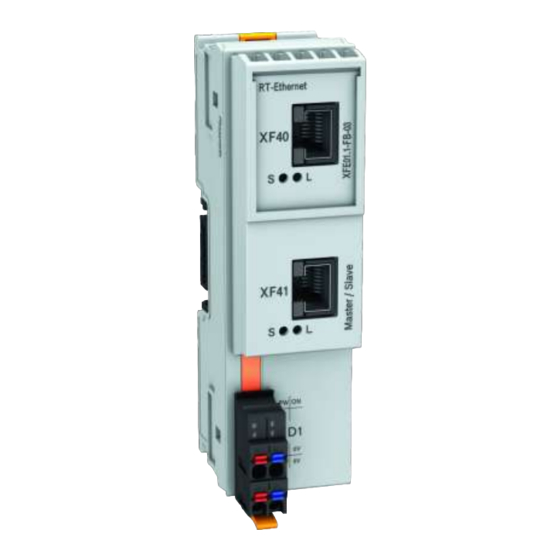
Page 20: Interfaces
Bosch Rexroth AG Extension Modules Profibus, RT- Ethernet, Sercos, CAN Interfaces 9 Interfaces Fig. 9-1: Interfaces of the extension modules NOTICE Attaching and detaching connections under voltage can damage the extension modules and the control! Switch off the supply voltage before attaching or detaching any connections! - Page 21 Extension Modules Profibus, RT- Bosch Rexroth AG Ethernet, Sercos, CAN Interfaces Name Connection type Connector type Mating connector and cable (Integrated) (From outside) Ethernet RJ45 socket RJ45 plug ⑤ 8-pin 8-pin Ethernet RJ45 socket RJ45 plug ⑥ 8-pin 8-pin CAN extension module...
-
Page 22: Mounting, Demounting And Electric Installationi
Bosch Rexroth AG Extension Modules Profibus, RT- Ethernet, Sercos, CAN Mounting, demounting and electric installationI 10 Mounting, demounting and electric installationI 10.1 Housing dimensions 54.8 * 41.6 50.8 52.4 ② The dimensions depend on the respec- Mounting rail center tive extension module ①... - Page 23 Extension Modules Profibus, RT- Bosch Rexroth AG Ethernet, Sercos, CAN Mounting, demounting and electric installationI To ensure EMC safety, connect all shieldings directly at the control cabinet entrance to a common FE ground line. The shielding connection set for the S20 modules may not be set for the extension modules.
- Page 24 Bosch Rexroth AG Extension Modules Profibus, RT- Ethernet, Sercos, CAN Mounting, demounting and electric installationI – They have a counterpressure against the engaging forces when mounting the modules in series to the control. Do not route cables parallel to motor cables or other strong interference sour- ●...
-
Page 25: Mounting
Extension Modules Profibus, RT- Bosch Rexroth AG Ethernet, Sercos, CAN Mounting, demounting and electric installationI 10.3 Mounting NOTICE Damages at the contacts by tilting the modules Place the modules vertically on the mounting rail and remove the modules verti- cally from the mounting rail as well. -
Page 26: Demounting
Bosch Rexroth AG Extension Modules Profibus, RT- Ethernet, Sercos, CAN Mounting, demounting and electric installationI Fig. 10-5: Connect extension bus base modules among each other and with the con- trol bus base module 4. Fit the extension modules and the XMx control on the bus base module. -
Page 27: Electric Installation
10.5.1 External power supply unit All control components are supplied from 24 V voltage supplies. Use the Bosch Rexroth power supply unit VAP01.1H-W23-024-010-NN, part num- ber R911171065, for the logic supply. For further information on the external power supply unit and on the creation of overvoltage categories, refer to the documentation of the power supply unit. - Page 28 Bosch Rexroth AG Extension Modules Profibus, RT- Ethernet, Sercos, CAN Mounting, demounting and electric installationI The same external power supply unit has to supply the 24 V voltage supply of the XMx control and the extension modules. Connect the voltage supply to the XD1 plugs of the XMxx control and then bridge...
-
Page 29: Voltage Supply For The Control And For The Extension Modules
Extension Modules Profibus, RT- Bosch Rexroth AG Ethernet, Sercos, CAN Mounting, demounting and electric installationI 24 V ① ④ 24 V voltage supply XM2x control ② ⑤ Top-hat rail S20 Module ③ Extension module Fig. 10-8: Not allowed voltage supply 10.5.2 Voltage supply for the control and for the extension modules... -
Page 30: Voltage Supply
Bosch Rexroth AG Extension Modules Profibus, RT- Ethernet, Sercos, CAN Device description Power connector XD1 Fig. 10-9: Power connector XD1 Connector contact Signal Function a1, a2 +24 V +24 V DC supply voltage (U b1, b2 GND (U ) (ground supply voltage) Tab. -
Page 31: Leds
Extension Modules Profibus, RT- Bosch Rexroth AG Ethernet, Sercos, CAN Device description 12.1 LEDs 12.1.1 LEDs on extension modules For the error diagnostics, multiple LEDs indicating the operating state of the ex- tension module are located on its front. LEDs... -
Page 32: Led On Xd1 Plug
Bosch Rexroth AG Extension Modules Profibus, RT- Ethernet, Sercos, CAN Error causes and troubleshooting Color Function LED displays the bus error acc. to the CANopen standard "CiA 303 Part 3: Indicator Specification" Green LED displays the bus state acc. to the CANopen standard "CiA 303 Part 3: Indicator Specification"... -
Page 33: Error Cases After Commissioning The Can Module
Extension Modules Profibus, RT- Bosch Rexroth AG Ethernet, Sercos, CAN Error causes and troubleshooting LED display Cause LED is off 24 V voltage errors: 24 V supply voltage is not connected ● 24 V supply voltage is connected with reverse po- ●... -
Page 34: Maintenance
Maintenance work in the device is only permis- sible by skilled staff! If hardware or software components have to be exchanged, please contact the Bosch Rexroth Service or ensure that only skilled staff changes the respective components. 14.2 Regular maintenance tasks... -
Page 35: Ordering Information
Extension Modules Profibus, RT- Bosch Rexroth AG Ethernet, Sercos, CAN Ordering information 15 Ordering information 15.1 Type code Type short description 1 2 3 4 5 6 7 8 9 0 1 2 3 4 5 Example: X F E 0 1 . 1 - F B - 1 0 Device type 1 I/O box.... -
Page 36: Accessories And Spare Parts
The packaging material consists of cardboard, plastics, wood or styrofoam. Packaging material can be recycled anywhere. For ecological reasons, please do not return empty packages to Bosch Rexroth. 17 Service and support Our worldwide service network provides an optimized and efficient support. - Page 37 Extension Modules Profibus, RT- Bosch Rexroth AG Ethernet, Sercos, CAN Service and support Additional information on service, repair (e.g. delivery addresses) and training can be found on our internet sites. Service worldwide Outside Germany, please contact your local service office first. For hotline num- bers, refer to the sales office addresses on the internet.
- Page 38 Bosch Rexroth AG Extension Modules Profibus, RT- Ethernet, Sercos, CAN 32/37 DOK-CONTRL -XFE**EXTMOD-IT04-EN-P...
-
Page 39: Index
Extension Modules Profibus, RT- Bosch Rexroth AG Ethernet, Sercos, CAN Index Index 0 … 9 24 V voltage supply....... 24 Hazard warning....... 4 Helpdesk........30 Hotline.......... 30 Housing dimensions...... 16 Accessories........6 Ambient conditions......7 ANSI Z535.6-2006......4 Atex..........11 IECEx.......... - Page 40 Bosch Rexroth AG Extension Modules Profibus, RT- Ethernet, Sercos, CAN Index Signal words........4 Spare parts........6 Standards........9 Suggestions........2 Support........30 Symbols used......... 5 Target groups........1 Technical data......... 8 Troubleshooting......26 Type code........29 Type plate........3 UL/CSA certified......
- Page 41 Extension Modules Profibus, RT- Bosch Rexroth AG Ethernet, Sercos, CAN 35/37 DOK-CONTRL -XFE**EXTMOD-IT04-EN-P...
- Page 42 Bosch Rexroth AG Extension Modules Profibus, RT- Ethernet, Sercos, CAN 36/37 DOK-CONTRL -XFE**EXTMOD-IT04-EN-P...
- Page 43 Extension Modules Profibus, RT- Bosch Rexroth AG Ethernet, Sercos, CAN Notes...
- Page 44 Bosch Rexroth AG Electric Drives and Controls P.O. Box 13 57 97803 Lohr, Germany Bgm.-Dr.-Nebel-Str. 2 97816 Lohr, Germany Phone +49 9352 18 0 Fax +49 9352 18 8400 www.boschrexroth.com/electrics *R911345570* R911345570 DOK-CONTRL -XFE**EXTMOD-IT04-EN-P...
Need help?
Do you have a question about the Rexroth IndraControl XFE 01.1 Series and is the answer not in the manual?
Questions and answers