Table of Contents

Subscribe to Our Youtube Channel
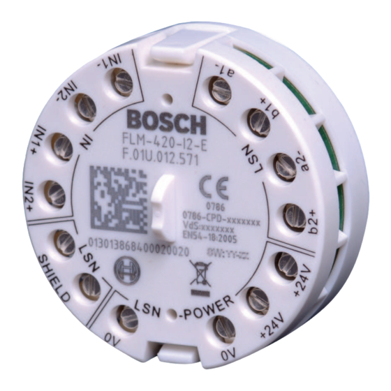
Related Manuals for Bosch FLM-420-I2-E


Summary of Contents for Bosch FLM-420-I2-E
- Page 1 Input Interface Module Type In‑built FLM‑420‑I2‑E Installation Guide deutsch türkçe english español français italiano nederlands polski português român русский...
- Page 3 Note di sicurezza nl nederlands Veiligheidsvoorschriften pl polski Uwagi dotyczące bezpieczeństwa pt português Notas sobre segurança ro român Note de siguranţă ru русский Замечания по технике безопасности tr türkçe Güvenlik Notları Bosch Sicherheitssysteme GmbH Installation Guide 2018.11 | 7 | F.01U.012.987...
- Page 4 Linienüberwachung mit EOL-Widerstand R Σ = R Contact monitoring Kontaktüberwachung ≤ 3 m ≤ 3 m ≤ 50 Voltage Monitoring (0 - 30 V DC) Spannungsüberwachung (0 - 30 V DC) 2018.11 | 7 | F.01U.012.987 Installation Guide Bosch Sicherheitssysteme GmbH...
- Page 5 UEZ 2000 LSN Adresse panel/Zentrale UGM 2020 Automatic addressing, T-taps not possible Automat. Adressierung, T-Taps nicht möglich Manual addressing 1 - 254 Manuelle Adressierung T-taps not possible 255=CL T-Taps nicht möglich Bosch Sicherheitssysteme GmbH Installation Guide 2018.11 | 7 | F.01U.012.987...
- Page 6 All | Graphics Input Interface Module Type In-built 255=CL 2018.11 | 7 | F.01U.012.987 Installation Guide Bosch Sicherheitssysteme GmbH...
- Page 7 Input Interface Module Type In-built Graphics | All Bosch Sicherheitssysteme GmbH Installation Guide 2018.11 | 7 | F.01U.012.987...
- Page 8 All | Graphics Input Interface Module Type In-built 2018.11 | 7 | F.01U.012.987 Installation Guide Bosch Sicherheitssysteme GmbH...
-
Page 9: Technische Daten
Die Adresseinstellung erfolgt über die 8 DIP-Schalter mit einem geeigneten spitzen Gegenstand, siehe Abbildung 2. Die Einbauversion FLM-420-I2-E kann unter Putz in Standardgerätedosen gemäß EN 60670 eingebaut werden (z. B. in Schalterdosen), siehe Abbildung 3. Alternativ kann er in Geräten eingebaut werden (siehe Abbildung 4). - Page 10 Unterer Schwellenwert < oberer Schwellenwert 10,2 VDC (±0,5 VDC) – Gesamtwiderstand R 21,2 VDC (±0,5 VDC) = R + R ≤ 50 Ω Σ Hinweis! Elektrische Daten für den integrierten Kurzschlussisolator gemäß EN 54-17:2005 finden Sie in der Installationsanleitung F.01U.003.287 für FLM-I-420-S. 2018.11 | 7 | F.01U.012.987 Installation Guide Bosch Sicherheitssysteme GmbH...
-
Page 11: Safety Notes
Address setting is carried out using the 8 DIP switches and a suitable pointed object, see graphic 2. The FLM-420-I2-E Type In-built can be flush mounted in standard device boxes in accordance with EN 60670 (e.g. in standard switch boxes), see graphic 3. Alternatively, it can be installed in the devices, see graphic 4. - Page 12 R 21.2 V DC (± 0.5 V DC) = R + R ≤ 50 Ω Σ Notice! Electrical data for the built-in short circuit isolator according to EN 54-17:2005, you find in F.01U.003.287 FLM-I 420-S Installation Guide. 2018.11 | 7 | F.01U.012.987 Installation Guide Bosch Sicherheitssysteme GmbH...
-
Page 13: Notas De Seguridad
La configuración de la dirección se lleva a cabo utilizando los 8 conmutadores DIP y un objeto puntiagudo apropiado (consulte el gráfico 2). El tipo FLM-420-I2-E integrado se puede montar empotrado en cajas para dispositivos estándar conforme a EN 60670 (por ejemplo, en cajas de interruptores estándar). Consulte el gráfico 3. - Page 14 21,2 V CC (± 0,5 V CC) = R + R ≤ 50 Ω Σ Aviso! Puede consultar los datos eléctricos para el aislador de cortocircuito integrados según la norma EN 54-17:2005 en F.01U.003.287 Guía de instalación de FLM-I S-420. 2018.11 | 7 | F.01U.012.987 Installation Guide Bosch Sicherheitssysteme GmbH...
-
Page 15: Remarques De Sécurité
Pour paramétrer l'adressage, munissez-vous des 8 commutateurs DIP et d'un objet pointu (voir figure 2). Le module intégré FLM-420-I2-E peut être encastré dans des boîtiers standard conformément à la norme EN 60670 (par exemple, dans des boîtes de distribution), voir la figure 3. Il peut aussi être installé... - Page 16 R 21,2 Vcc (± 0,5 Vcc) = R + R ≤ 50 Ω Σ Remarque! Caractéristiques électriques pour le sectionneur intégré conformément à la norme EN 54-17:2005, qui figure dans le guide d'installation F.01U.003.287 FLM-I 420-S. 2018.11 | 7 | F.01U.012.987 Installation Guide Bosch Sicherheitssysteme GmbH...
-
Page 17: Note Di Sicurezza
L'impostazione degli indirizzi viene effettuata mediante gli 8 interruttori DIP ed un oggetto appuntito adatto, vedere la figura 2. Il tipo FLM-420-I2-E incorporato può essere montato ad incasso nelle scatole per dispositivi standard in conformità alla normativa EN 60670 (ad esempio nelle cassette elettriche standard), vedere la figura 3. - Page 18 21,2 VDC (± 0,5 VDC) = R + R ≤ 50 Ω Σ Avviso! Dati elettrici per il dispositivo di isolamento per cortocircuiti integrato in conformità alla normativa EN 54-17:2005, presente nella Guida all'installazione di F.01U.003.287 FLM-I 420-S. 2018.11 | 7 | F.01U.012.987 Installation Guide Bosch Sicherheitssysteme GmbH...
-
Page 19: Technische Specificaties
De adresinstelling wordt uitgevoerd met behulp van de 8 DIP-switches en een geschikt puntig voorwerp, zie afbeelding 2. Het type FLM-420-I2-E kan worden ingebouwd in standaard inbouwdozen conform EN 60670 (bijvoorbeeld in standaard schakeldozen), zie afbeelding 3. In plaats hiervan kan de module tevens worden geïnstalleerd in de apparaten, zie afbeelding 4. - Page 20 10,2 VDC (± 0,5 VDC) – totale lijnweerstand R 21,2 VDC (± 0,5 VDC) = R + R ≤ 50 Ω Σ Bericht! Elektrische gegevens voor de ingebouwde kortsluitisolator conform EN 54-17: 2005 vindt u in de F.01U.003.287 FLM-I 420-S Installatiehandleiding. 2018.11 | 7 | F.01U.012.987 Installation Guide Bosch Sicherheitssysteme GmbH...
-
Page 21: Uwagi Dotyczące Bezpieczeństwa
Ustawianie adresów jest przeprowadzane przy użyciu 8 mikroprzełączników i odpowiedniego ostro zakończonego przedmiotu, patrz grafika 2. Moduł FLM-420-I2-E do wbudowania można zamontować podtynkowo w standardowych obudowach urządzeń w sposób zgodny z normą EN 60670 (np. w standardowych obudowach przełączników), patrz grafika 3. Alternatywnie można go zamontować w urządzeniach, patrz grafika 4. - Page 22 21,2 VDC (± 0,5 VDC) = R + R ≤ 50 Ω Σ Uwaga! Dane elektryczne dotyczące wbudowanych izolatorów zwarć zgodnych z normą EN 54-17:2005 można znaleźć w dokumencie F.01U.003.287 Instrukcja instalacji FLM-I 420-S. 2018.11 | 7 | F.01U.012.987 Installation Guide Bosch Sicherheitssysteme GmbH...
-
Page 23: Notas Sobre Segurança
A definição de endereço é executada utilizando os 8 interruptores DIP e um objeto pontiagudo adequado (veja o gráfico 2. O FLM-420-I2-E, de montagem embutida, pode ser montado embutido em caixas de dispositivos standard, de acordo com a norma EN 60670 (por exemplo, em caixas de interruptores standard), veja o gráfico 3. - Page 24 21,2 V CC (± 0,5 V CC) = R + R ≤ 50 Ω Σ Informação! É possível encontrar os dados elétricos do isolador de curto-circuito integrado de acordo com a EN 54-17:2005 no Manual de instalação F.01U.003.287 FLM-I 420-S. 2018.11 | 7 | F.01U.012.987 Installation Guide Bosch Sicherheitssysteme GmbH...
-
Page 25: Specificaţii Tehnice
Setarea adresei este efectuată utilizând comutatoarele DIP 8 şi un obiect ascuţit corespunzător, consultaţi imaginea 2. FLM-420-I2-E de tip încorporat poate fi montat aliniat, în cutii standard pentru dispozitive, în conformitate cu EN 60670 (de exemplu, în cutii pentru comutatoare standard), consultaţi imaginea 3. - Page 26 R 21,2 V CC (± 0,5 V CC) = R + R ≤ 50 Ω Σ Notificare! Specificaţiile electrice privind izolatorul de scurtcircuit încorporat, în conformitate cu EN 54-17:2005, se găsesc în Ghidul de instalare F.01U.003.287 FLM-I 420-S. 2018.11 | 7 | F.01U.012.987 Installation Guide Bosch Sicherheitssysteme GmbH...
-
Page 27: Принцип Действия
Настройка адреса выполняется при помощи 8 переключателей DIP и подходящего заостренного предмета (см. рис. 2). Встраиваемая модель FLM-420-I2-E монтируется заподлицо в стандартные корпуса устройств в соответствии с EN 60670 (например, в стандартный распределительный блок), см. рисунок 3. Или же модель может устанавливаться в устройства (см. рис. 4). - Page 28 21,2 В пост. тока (± 0,5 В пост. тока) = R + R ≤ 50 Ом Σ Замечание! Электрические характеристики встроенного изолятора для защиты от короткого замыкания в соответствии с EN54-17 можно найти в руководстве по установке F.01U.003.287 FLM-I 420-S. 2018.11 | 7 | F.01U.012.987 Installation Guide Bosch Sicherheitssysteme GmbH...
-
Page 29: Güvenlik Notları
Adres ayarlama, 8 DIP anahtarı ve sivri uçlu uygun bir nesne kullanılarak yapılır, bkz. grafik 2. Dahili FLM-420-I2-E Tipi standart cihaz kutularına EN 60670 uyarınca (ör. standart anahtar kutularına) gömme olarak monte edilebilir, bkz. grafik 3. Alternatif olarak, cihazların içine de monte edilebilir, bkz. - Page 30 < yüksek eşik 10,2 V DC (± 0,5 V DC) – toplam hat direnci R 21,2 V DC (± 0,5 V DC) = R + R ≤ 50 Ω Σ Uyarı! F.01U.003.287 FLM-420-S Kurulum Kılavuzu'nda bulabileceğiniz EN 54-17:2005'e göre dahili kısa devre yalıtıcısının elektriksel verileri. 2018.11 | 7 | F.01U.012.987 Installation Guide Bosch Sicherheitssysteme GmbH...
- Page 32 Bosch Sicherheitssysteme GmbH Robert-Bosch-Ring 5 85630 Grasbrunn Germany www.boschsecurity.com © Bosch Sicherheitssysteme GmbH, 2019...
Need help?
Do you have a question about the FLM-420-I2-E and is the answer not in the manual?
Questions and answers