
Related Manuals for JLG X20JPLUS


Summary of Contents for JLG X20JPLUS
- Page 1 Operator, Safety, Maintenance and service Manual Original Instructions ‐ Keep this manual with the machine at all times Boom Lift Models X20JPLUS MUX20JP021602 2016, revision02...
-
Page 3: Table Of Contents
Technical data Diesel engine ...............Pag. 20 7.4.3. Hydraulic system technical specifications.........Pag. 21 7.4.4. Electrical system technical specifications thermal engine....Pag. 21 7.4.5. Electrical system technical specifications lithium ......Pag. 21 7.5. Terminology...................Pag. 23 7.6. General safety standards..............Pag. 25 7.7. Clothing and protective equipment ...........Pag. 26 7.8. Safety valves and electrical system safety components....Pag. 26 7.9. Fire prevention ..................Pag. 27 7.10. Preventing damage caused by washing the machine......Pag. 27 7.10.1. Cleaning the machine ................Pag. 27 7.10.2. Washing the outside of the machine ..........Pag. 28 7.10.3. Cleaning the electrical system .............Pag. 28 7.10.4. After cleaning..................Pag. 28 7.11. Preventing damage that may be caused by the machine during work..Pag. 29 7.12. Safety warnings ..................Pag. 30 Boom Lift Models X20JPLUS... - Page 4 Joystick....................Pag. 59 9.1.3. Push buttons ..................Pag. 61 9.2. Foot switch (optional)................Pag. 64 9.3. Control position..................Pag. 65 9.3.1. Control position in the basket .............Pag. 65 9.3.2. Control position at the ground............Pag. 65 9.3.3. Emergency control position..............Pag. 66 9.3.4. Maintenance control position..............Pag. 67 9.4. Remote Control MOVE (optional) ............Pag. 69 9.5. SkyGuard system (optional) ............Pag. 69 Emergency device ................Pag. 71 10.1. Emergency stop button ................Pag. 71 10.2. Hand pump....................Pag. 72 10.3. Solenoid valves for emergency descent ..........Pag. 73 10.4. Safety device bypass key..............Pag. 73 10.5. Emergency position controls ...............Pag. 74 Boom Lift Models X20JPLUS...
- Page 5 11.4.10. Automatic lowering and raising of the stabilisers ......Pag. 102 11.4.11. Track extension..................Pag. 104 11.4.12. Moving the basket ................Pag. 106 11.4.13. Manually levelling of the basket ............Pag. 109 11.5. Aerial part emergency manoeuvres ..........Pag. 112 11.5.1. Activation of emergency descent from the basket ......Pag. 112 11.5.2. Operating the machine from the emergency control position on the ground if the operator is taken ill .............Pag. 114 11.5.3. Emergency descent in the case where the stabilisers are accidentally retracted ....................Pag. 117 11.5.4. Emergency descent controlled from the ground using the hand pump in the event of faults on all energy supply systems......Pag. 120 11.5.5. Emergency operation of the undercarriage in the event of movements of the aerial part ..................Pag. 124 11.5.5.1. Machine realignment ................Pag. 124 11.5.5.2. Moving the undercarriage with the machine not aligned.....Pag. 125 11.5.6. Emergency operations on the carriage: moving the platform stabilisers using the hand pump to allow the machine to be transported ..Pag. 128 Boom Lift Models X20JPLUS...
- Page 6 12.6.3. C‐ Annual inspections ................Pag. 153 12.6.4. D‐ Structural inspection ..............Pag. 154 12.6.5. E‐ Maintenance ..................Pag. 154 12.7. General periodical checks ..............Pag. 155 12.8. Maintenance on rubber tracks............Pag. 156 12.8.1. Rubber tracks tension check ..............Pag. 156 12.8.2. Tensioning rubber track ..............Pag. 157 12.8.3. Removing rubber track...............Pag. 157 12.8.4. Installing rubber track ................Pag. 159 12.9. Checking tightness of nuts and bolts ..........Pag. 159 12.10. Hydraulic oil level check..............Pag. 164 12.11. Checking for leaks in the hydraulic system ........Pag. 164 12.12. Checking the condition of the filter cartridge .........Pag. 164 12.13. Checking that all the plates are present on the machine and intact ...Pag. Boom Lift Models X20JPLUS...
- Page 7 12.19. Servicing the engine thermic version ..........Pag. 182 12.20. Start‐up of the machine after maintenance ........Pag. 182 Safety standards for transport ............Pag. 183 13.1. Removing the basket................Pag. 183 13.2. Loading and unloading the machine on transport vehicles using ramps Pag. 185 13.3. Lifting the machine ................Pag. 187 13.3.1. Lifting the machine using a forklift ..........Pag. 187 13.3.2. Lifting the machine using ropes or chains........Pag. 189 13.4. Transporting the machine..............Pag. 191 Service menu on the remote control ..........Pag. 192 14.1. Input menu...................Pag. 192 14.2. Language menù ...................Pag. 192 14.3. Errors menu ..................Pag. 192 14.4. Working hours menu................Pag. 193 14.5. Joystick menu..................Pag. 193 Hydraulic system ................Pag. 194 Wiring diagram ..................Pag. 197 Boom Lift Models X20JPLUS...
- Page 8 MUX20JP021602 Boom Lift Models X20JPLUS...
- Page 9 MUX20JP021602 JLG Industries, Inc. 13224 Fountainhead Plaza Hagerstown, MD 21742 or Your Local JLG Office ʺWorldwide locations (p. 202)ʺ In USA: Toll Free: 877‐JLG‐SAFE (877‐554‐7233) Outside USA: Phone.: 240‐420‐2661 Fax: 301‐745‐3713 E‐mail: ProductSafety@JLG.com For: • Accident Reporting • Product Safety Publications • Current Owner Updates • Questions Regarding Product Safety • Standards and Regulations Compliance Information • Questions Regarding Special Product Applications • Questions Regarding Product Modifications Boom Lift Models X20JPLUS...
-
Page 10: Preface
PREFACE MUX20JP021602 1. PREFACE The aim of this manual is to provide the user with the necessary instructions and essential operating procedures to ensure correct and safe use of the machine for its intended purposes, as well as to prevent serious injury to the operator and other persons. This manual describes the warning signs used to draw the readerʹs attention to several particularly important warnings. The safety warnings are divided into three main types, which are identified and described below. 1.1. ATTENTION ‐ DANGER This symbol indicates that the situation described, if not prevented, can lead to serious injury or death of the persons involved (operator, ground staff, staff present in proximity to the machine, maintenance technicians etc.). 1.2. WARNING This symbol indicates that the situation described represents a potential risk for the structure of the machine. Dangerous situations may be determined by this condition (including injury or death) for the persons involved. 1.3. NOTE This symbol indicates tips or additional notes useful for the operator or for those who must perform maintenance/repair on the machine. Original languages of the manufacturer: Italian and English. All other languages are copies of the original instructions. Boom Lift Models X20JPLUS... -
Page 11: How To Use The Manual
MUX20JP021602 HOW TO USE THE MANUAL 2. HOW TO USE THE MANUAL It is mandatory to keep to all the instructions given in this manual. This ma‐ nual must be carefully read and understood before operating the machine. As this manual is an essential work tool, it must be kept with the machine at all times, in the special compartment, so as to be available for clarification whenever required. Fig. 1 Position of manual on machine As the manufacturer cannot control the conditions of the machine and the opera‐ tions this is used for, the user is responsible for ensuring compliance with the sa‐ fety procedures described in this manual. Every machine supplied is thoroughly adjusted and tested before being delive‐ red. The operator does not need to perform any adjustments before using the ma‐ chine. Every alteration and/or modification of the features of the original machine design without previous written authorization from the constructor are prohibi‐ ted and the responsibility for these actions falls on the operator. Boom Lift Models X20JPLUS... - Page 12 HOW TO USE THE MANUAL MUX20JP021602 The employer must make sure that the operator has the requisites necessary to operate the machine correctly and that such operator has carefully examined and understood the information given in this user and operation manual, re‐ ceiving suitable training regarding use of the machine in standard and emer‐ gency conditions. The employer must also train operators regarding any national standards that are in addition to the instructions contained in this document. If the manual is damaged or lost, a copy must be requested directly from the ma‐ nufacturer. All of the photos and drawings in this manual have been added to simplify com‐ prehension by the reader. Your machine may differ from the photos and drawings provided. Boom Lift Models X20JPLUS...
-
Page 13: Normative Reference
MUX20JP021602 NORMATIVE REFERENCE 3. NORMATIVE REFERENCE The machine has been designed, built and inspected according to that prescribed in the EN280 harmonised standard, which supplies the presumption of conformi‐ ty with the Essential Safety Requisites of the 2006/42/CE Machinery Directive even if a type C Voluntary Technical Standard. According to that stated in EN280, the platform is classified in GROUP B, as the vertical projection of the centre of gravity of the load can be outside of the tilting lines and in TYPE 1 as traversing is only allowed with the platform at rest. The stability tests of the machine have been made in accordance with what de‐ scribed in the EN280 and have been successful. In addition what prescribed in this manual it is necessary to apply the technical requirements of the following national/international safety standards: • UNI ISO 18893 • ISO 16368 • ISO 18878 With the exception of stricter local or national regulations in the working area of the MEWP. Boom Lift Models X20JPLUS... -
Page 14: Warranty
WARRANTY MUX20JP021602 4. WARRANTY On purchasing a machine, a warranty and inspection certificate is issued that cle‐ arly indicates the warranty terms and where any interventions on the machine must be reported. Boom Lift Models X20JPLUS... -
Page 15: Liability
MUX20JP021602 LIABILITY 5. LIABILITY The Constructor is exonerated from any liability and obligation for any injury/da‐ mage caused to persons/objects due to any of the reasons listed below: • Failure to comply with the instructions indicated in this USE AND MAINTE‐ NANCE MANUAL regarding running, use and maintenance of the machine; • Violent or sudden actions or incorrect manoeuvres when using or servicing the machine; • Modifications made to the structure or machine components without pre‐ vious authorisation from the Constructor and/or without the use of suitable equi‐ pment; • Strange events with respect to normal and correct use of the machine, descri‐ bed in this USE AND MAINTENANCE MANUAL; • Use of non‐original spare parts not authorised by the manufacturer; Boom Lift Models X20JPLUS... -
Page 16: Ec Declaration Conformity
This declaration conforms with the requirements of annex II-A of the council directive 2006/42/EC Any modification to the above described machine violates the validity of this declaration. Machine manufactured for JLG Industries Inc. by HINOWA S.p.a via Fontana 37054 NOGARA VR Italy Fig. 2 EC Declaration Conformity... - Page 17 Position: Director of Engineering-Europe Place: Bruntingthorpe, UK Remark: Any modification to the above described machine violates the validity of this declaration. Machine manufactured for JLG Industries Inc. by HINOWA S.p.a via Fontana 37054 NOGARA VR Italy Fig. 3 EC Declaration Conformity Boom Lift Models X20JPLUS...
-
Page 18: Technical Informations
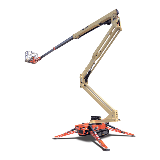
TECHNICAL INFORMATIONS MUX20JP021602 7. TECHNICAL INFORMATIONS 7.1. DESCRIPTION OF THE MACHINE The machine is a self‐propelled hydraulic lifting device, equipped with a rotating work basket positioned at the top of an extensible articulated structure, which also rotates. The lifting device is destined for the positioning of persons and their equipment and materials in high positions with respect to ground level. Refer to relevant paragraph in respect of the control stations ʺControl position (p. 65)ʺ Boom Lift Models X20JPLUS... -
Page 19: Machine Identification Plate
MUX20JP021602 TECHNICAL INFORMATIONS 7.2. MACHINE IDENTIFICATION PLATE The manufacturer plate is placed on the protection of the aerial part hydraulic di‐ stributor or on the machine frame near of the lifting forks fasteners. xsm1;Manufactured by HINOWA S.p.A. Via Fontana 37054 NOGARA (VR) JLG Industries. Inc - McConnellsburg. PA - USA ITALY Model Serial number Date of manufacture G.V.W. (Dry) 1° MAXIMUM ALLOWABLE OPERATING INCLINATION 2x80 12.5 07253100 Fig. 4 Example CE plate... -
Page 20: Overall Dimensions Of The Machine
TECHNICAL INFORMATIONS MUX20JP021602 7.3. OVERALL DIMENSIONS OF THE MACHINE Maximum length in travel configuration with basket in‐ 5011 mm stalled Track width closed/open 795/1095 mm Maximum height in travel configuration with foot plates 1998 mm removed Maximum attachment angle 20° / 21° Maximum stabilisation angle 15° Max stabiliser base side (disc centre) 2922x2925 mm Fig. 5 Standard version with 2 person basket Boom Lift Models X20JPLUS... -
Page 21: Technical Data
9.20m Max horizontal outreach 9.70m Rotation (non‐continuous) 360° Basket rotation 124° (+/‐ 62°) Max ground reaction force for each stabilizer 2150 daN Max ground pressure for each stabilizer 3.04 daN/cm2 No. Of operators No. Of operators with optional single‐operator basket JIB ‐ type of articulated joint 89° (+0° / ‐89°) Max working gradient 1°/ 1,75% Max stabilization slope 15° Total weight in transport configuration petrol en‐ 2840Kg gine Total weight in transport configuration diesel 2940Kg Total weight in transport configuration lithium 2950Kg Electrical system voltage Max translation speed with standard 2nd speed 0,5/1,3/2,5 Km/h (thermic motor) Max translation speed with standard 2nd speed 0,83/1,6 Km/h (lithium) Travel/stab. System pressure 165bar Aerial part system pressure 210bar Boom Lift Models X20JPLUS... -
Page 22: Technical Data Petrol Engine
Make/Model HONDA iGX440 Fuel/Cooling Petrol / Air Power 9,5 Kw (12,7cv) / 3600rpm Max speed 3600 rpm Maximum torque 29,8 Nm / 2500rpm Number of cylinders Displacement 440 cm³ Sound power level at operatorʹs ear 88 dB Measured sound power level 102 dB Granted sound power level 104 dB 7.4.2. Technical data Diesel engine Make/Model PERKINS 402.05 Fuel/Cooling Diesel / Liquid Power 10,2 kW (14cv) / 3600rpm Max speed 3500 rpm Maximum torque 29,7 Nm / 2400rpm Number of cylinders Displacement 510 cm³ Sound power level at operatorʹs ear 90 dB Measured sound power level 102 dB Boom Lift Models X20JPLUS... -
Page 23: Hydraulic System Technical Specifications
40 l Pump petrol engine 2x4 cm³ Pump diesel engine 2x4 cm³ Hydraulic system max pressure 220 bar For further information, see the hydraulic diagram enclosed with the manual and the paragraph on maintenance of the hydraulic components. 7.4.4. Electrical system technical specifications thermal engine Battery 55‐60Ah ‐ 240‐680A ‐ 12V Alternator petrol engine 20 A (3600rpm) Alternator Diesel engine 14‐15 A (3600rpm) Electric motor rated voltage 230V ‐ 110V ‐ 120V Electric motor frequency 50Hz ‐ 50Hz ‐ 60Hz Electric motor rated power 2,2 kW ‐ 2,2 kW ‐ 1,2 kW For further information, see wiring diagram enclosed with the manual and the paragraph on maintenance of electrical components. 7.4.5. Electrical system technical specifications lithium Battery 90‐100 Ah Electric motor rated voltage 72 V Electric motor rated power 3,5 kW Onboard battery charger 220V+‐30V 50‐60 Hz 110V+‐30V 50‐60 Hz Full weight of the battery pack 180 Kg Boom Lift Models X20JPLUS... - Page 24 TECHNICAL INFORMATIONS MUX20JP021602 Sound power level at operatorʹs ear 70 dB Measured sound power level 86 dB Granted sound power level 88 dB For further information, see wiring diagram enclosed with the manual and the paragraph on maintenance of electrical components. Boom Lift Models X20JPLUS...
-
Page 25: Terminology
MUX20JP021602 TECHNICAL INFORMATIONS 7.5. TERMINOLOGY To make the contents of this manual easier to understand, the diagram provided below illustrates the terms used to identify the parts of the machine. Fig. 6 Terminology machine components LEGENDA Tracked undercarriage Revolving turret Turntable + rotation motor Emergency controls Base+electrical component compartment+oil tank Double gear pump Petrol/diesel engine / Battery pack + inverter + battery charger (LITHIUM MOTOR) Stabilizer Boom Lift Models X20JPLUS... - Page 26 TECHNICAL INFORMATIONS MUX20JP021602 Stabilizer cylinder Second arm tie rod Second arm Second‐third arm cylinder Second‐third arm transmission Second‐third arm connecting rod Basket levelling cylinder on the transmission Third arm Stabilizer plate JIB tie rod First extension arm Jib cylinder Right and left JIB arm Second extension arm Remote control Basket or cage Basket support Rotary actuator for basket rotation Basket levelling cylinder on the basket JIB transmission First‐second arm transmission First‐second arm cylinder First arm Electric motor Double gear pump Emergency hand pump Boom Lift Models X20JPLUS...
-
Page 27: General Safety Standards
• Before starting work, operators must receive complete and clear training re‐ garding the use of the machine in standard and emergency conditions. • They must examine, understand and take in all the instructions given in this user manual. They must be sure that the safety devices are in perfect wor‐ king order, perform the necessary checks on the machine and be familiar with the conditions of the ground on which the machine is going to be operated and stabilised. • The presence of at least one specialist operator is necessary on the ground du‐ ring work. This person must know how to use the machine, be aware of the con‐ tents of the USER AND OPERATION MANUAL and be able to intervene if necessary. Boom Lift Models X20JPLUS... -
Page 28: Clothing And Protective Equipment
PPE that the safety manager considers necessary based on the risk analysis performed are in perfect working con‐ dition. Warning USE THE TYPE‐APPROVED AND CERTIFIED SAFETY HARNESSES. BEFORE WORKING AT A HEIGHT, MAKE SURE THAT THE SAFETY HARNESSES ARE CORRECTLY FASTENED AND CONNECTED TO THE ANCHORAGE POINTS ON THE BASKET. THE USE OF HARNESSES IS COMPULSORY IN ACCORDANCE WITH LO‐ CAL LEGISLATION IN EACH INDIVIDUAL COUNTRY. IN COUNTRIES WHERE THE LAW DOES NOT REQUIRE THE USE OF SUCH SAFETY SY‐ STEMS, THE EMPLOYER AND/OR USER IS RESPONSIBLE FOR CHOOSING THE SYSTEM TO BE USED. 7.8. SAFETY VALVES AND ELECTRICAL SYSTEM SAFETY COMPONEN‐ It is prohibited to modify and/or tamper with the safety and control valves of the main hydraulic system and the adjustments of the electric plant. The Con‐ structor is not liable for injury to persons and damage to objects or to the ma‐ chine if the standard calibration of any hydraulic and electric/electronic component is tampered with. Boom Lift Models X20JPLUS... -
Page 29: Fire Prevention
7.10.PREVENTING DAMAGE CAUSED BY WASHING THE MACHINE Do not direct high pressure jets towards the electrical components while washing the machine. Do not use chemical detergents or petrol that would damage the plastic parts and the painting. BEFORE WASHING THE MACHINE, ALWAYS REMEMBER TO REMOVE THE REMOTE CONTROL AND CORRECTLY CLOSE THE REMOTE CON‐ TROL AND EQUIPMENT CONNECTION SOCKETS LOCATED ON THE MA‐ CHINE. 7.10.1.Cleaning the machine When washing the machine, the ignition block must be disengaged, the key removed and the emergency stop button pressed. Boom Lift Models X20JPLUS... -
Page 30: Washing The Outside Of The Machine
TECHNICAL INFORMATIONS MUX20JP021602 7.10.2.Washing the outside of the machine Always park the machine as shown in the figure ʺTerminology (p. 23)ʺ Never use flammable liquids. Clean the machine using water‐soluble detergents. Follow the instructions provi‐ ded by the manufacturer of the detergent. Do not remove protective covers and casings of any kind. If washing the machine with water cleaners, do not aim the spray di‐ rectly onto adhesive labels and rating plates. carefully protect all the important parts and above all the electrical components. The more the elevating platform is cleaned, the more it will need to be greased 7.10.3.Cleaning the electrical system Never clean the electric components with water, as this may cause damage to the electrical system of the machine. Only use dry detergents, in accordance with the manufacturerʹs in‐ structions. Never remove covers, guards and the like. 7.10.4.After cleaning Dry the machine carefully before starting it again (for example using compressed air). Boom Lift Models X20JPLUS... -
Page 31: Preventing Damage That May Be Caused By The Machine During Work
MUX20JP021602 TECHNICAL INFORMATIONS If, despite all the precautions, moisture has penetrated into the electric motor or other parts of the electric system, these must be dried before starting the machine. 7.11.PREVENTING DAMAGE THAT MAY BE CAUSED BY THE MACHINE DURING WORK When the machine has been stabilised and work has started, never enter its ope‐ rating area. Always operate the controls slowly and smoothly and avoid reversing the move‐ ments suddenly. When operating outside of the basket, ALWAYS keep a MINIMUM distance of 1 METRE from the machine. Boom Lift Models X20JPLUS... -
Page 32: Safety Warnings
Carefully read all the safety messages provided in this manual and the safety si‐ gns on the machine. Keep the safety signs in good condition and replace them if they are damaged. Make sure that any new components on the machine are pro‐ vided with the correct safety signs. 7.12.2.Noise and Vibration The Constructor declares that the platforms have been tested according to the pa‐ rameters of European directive 2000/14 EC, with the guaranteed sound power le‐ vel measurement shown on the machineʹs EC declaration of conformity. When operating the aerial part of the machine, this value is reduced even further as the basket moves away from the main source of noise. The vibrations transmitted to the operator from the controls and directly from the floor of the basket are lower than the maximum allowed limits 0,5 m/s2. Boom Lift Models X20JPLUS... -
Page 33: Decals On The Machine
MUX20JP021602 TECHNICAL INFORMATIONS 7.12.3.Decals on the machine Here we report the positions of the various boards with pictogram on the machi‐ Boom Lift Models X20JPLUS... - Page 34 TECHNICAL INFORMATIONS MUX20JP021602 Boom Lift Models X20JPLUS...
- Page 35 MUX20JP021602 TECHNICAL INFORMATIONS Boom Lift Models X20JPLUS...
- Page 36 06060000 06041200 06227200 100112548 1701542 1706898 1701505 06924300 06056300 1706493 06164600 06040500 06232100 06040900 07240300 06041300 07320400 1703814 07034200 06044000 07397200 160871000 1704277 160871000 1705828 07199100 07056700 06254800 1701499 06922700 07058800 07350300 06040300 06214200 1706098 06594500 07349200 07071000 Boom Lift Models X20JPLUS...
- Page 37 06085900 06706500 06998800 07242000 1702155 Language decals Position Code Quantity Position Code Quantity 172831IT 172831GB 06555300 06562600 06561200 06561200 06448200 06462700 06448100 06462100 07348900 073489GB 172831FR 172831DE 06562700 06562800 06561200 06561200 06462800 06462900 06462200 06462300 073489FR 073489DE 172831ES 172831NL Boom Lift Models X20JPLUS...
- Page 38 06562900 06563000 06561200 06561200 06463000 06463100 06462400 06462500 073489ES 073489NL 01 172831PT 172831DA 06563100 07138100 06561200 06561200 06463200 07138000 06462600 07137900 073489PT 073489DA 01 172831NO 172831SW 07162000 07137300 06561200 06561200 07161800 07137500 07161900 07137400 073489NO 01 073489SW 01 Boom Lift Models X20JPLUS...
- Page 39 MUX20JP021602 TECHNICAL INFORMATIONS Decals description Warning keep safe distance Sense of moving undercarriage defined as the direction forward. Obligation to read the manual before use of machine. Fixing point for transport indicates correct fixing point for transport of the machine. Crushing hazard feet indicates areas where there is a danger of cru‐ shing lower limbs for the operator. Crushing hazard person indicates areas where there is a danger of crushing upper limbs for the operator. Boom Lift Models X20JPLUS...
- Page 40 TECHNICAL INFORMATIONS MUX20JP021602 Lifting point indicates correct lifting points for lift the machine. Danger hight temperature. Engine oil level. Emergency device for aerial part device that allows to exclude the safety of the aerial part in case of emergency operations. Emergency device for undercarriage device that allows to exclude the safety of the undercarriage in case of emergency operations. Hydraulic oil level. Boom Lift Models X20JPLUS...
- Page 41 MUX20JP021602 TECHNICAL INFORMATIONS Forbidden lifting point. Do not wash with water. Hand pump legend quick instructions for using the emergency hand pump. Use safety harnesses, use protective equipment (helmet), prohibi‐ tion of weld on the machine, prohibition of use systems to increase the area of work inside the basket , prohibition of working in the vi‐ cinity of voltage electric, prohibition of use of the platform for rai‐ sing loads. Battery pack warnings. Corrosive liquid, presence of highly corrosive liquid, dangerous to the body and eyes. High voltage, presence of high voltage with danger of electric shock. Danger of explosion, formation of potentially explosive mixture in‐ side the battery. No naked flames, do not smoke or use naked flames when rechar‐ ging and near the vehicle. Risk of explosion. Recycling, it is highly recommended to comply with legislative and environmental standards as regards the demolition, reuse, recycling and recovery of materials. Lifting points with forklift, indicates the lifting points with forklift. Boom Lift Models X20JPLUS...
- Page 42 TECHNICAL INFORMATIONS MUX20JP021602 Replace stickers and plates if there is any sign of wear. Failure to heed any warnings due to a safety sticker being damaged, lost or ignored may cause serious accidents. Anchor position in basket indicates the position of the anchor hooks to which fasten the operatorʹs safety sling. Boom Lift Models X20JPLUS...
-
Page 43: Safety Device
The service function on the remote control can be used as an aid for checking electric safety devices. Never intervene on the safety devices. If they are tampered with, the manufacturer declines all liability regarding any accidents that may be due to such tampering. It is prohibited to tamper with the lead sealing or setting of the ma‐ ximum pressure valves and the adjustments of the electrical compo‐ nents. If they are tampered with the manufacturer declines all liability for any accidents that may be due to such tampering. The Constructor is not liable for any damage/injury caused by the machine to objects and/or persons due to failure to comply with the above in‐ structions. Boom Lift Models X20JPLUS... -
Page 44: Battery Cut-Out Switch
SAFETY DEVICE MUX20JP021602 8.1. BATTERY CUT‐OUT SWITCH Fig. 7 Battery cut out switch thermal En‐ Fig. 8 Battery cut out switch Lithium ver‐ gine version sion This device is used to isolate the machineʹs electrical circuit. It is well visible and easily accessed without using tools. It only needs to be activated for prolonged machine downtime or maintenance operations. Turning the key clockwise closes the machineʹs electrical circuit, while turning it anticlockwise isolates the machi‐ neʹs electrical circuit and the key can be removed. Before disconnecting the battery by means of this device, make sure that the engine key is in position “off” and the remote control and electronic board are off. 8.2. DISTRIBUTOR PRESSURE RELIEF VALVES Fig. 9 Aerial part pressure relief valve Fig. 10 Ground part pressure relief valve 1 Boom Lift Models X20JPLUS... -
Page 45: Cylinder Stop Valves
MUX20JP021602 SAFETY DEVICE All platform distributors have a pressure relief valve that limits the pressure in‐ side the system to the value set for the same valve. These valves are set when the platform is tested by qualified personnel and must not be tampered with for any reason whatsoever. 8.3. CYLINDER STOP VALVES Fig. 11 Cylinder stop valves Fig. 12 Cylinder stop valves The stabiliser cylinders have a double stop valve which in case of system break‐ down or hose breakage stops the cylinder preventing dangerous platform insta‐ bility situations. All cylinders that move the aerial part of the platform structure are fitted with a stop valve which in case of system breakdown or hose breakage stops the cylinder preventing the basket from falling due to gravity. These valves are calibrated in the platform inspection phase by the constructor and must not be tampered with for any reason. Boom Lift Models X20JPLUS... -
Page 46: Alignment Photocells Of The Aerial Part
SAFETY DEVICE MUX20JP021602 8.4. ALIGNMENT PHOTOCELLS OF THE AERIAL PART Fig. 13 Photocells Fig. 14 Reflector The platform has two safety photocells that ensure that the aerial part of the ma‐ chine is completely lowered and aligned with the base and that the telescopic arm is completely retracted. When these conditions are not met, a signal is sent that disables the movement of the stabilisers. 8.5. STABILIZER POSITION MICRO SWITCHES Fig. 15 Stabilizer micro switches Fig. 16 Indicator light plate on the ground The position of the stabilisers and their contact with the ground are detected by 4 micro switches positioned near the stabiliser cylinder rod fastening pin. The mi‐ cro switches fixed to the stabiliser must be released when the stabiliser rests on the ground. Boom Lift Models X20JPLUS... -
Page 47: Jib Position Micro Switch
MUX20JP021602 SAFETY DEVICE Check the correct operation of the micro switches every day. 8.6. JIB POSITION MICRO SWITCH Fig. 17 JIB micro switch The position of the jib arm is detected by a micro switch that is secured to the jib arm itself. The micro switch must be released when the jib arm is closed. Check the condition and correct operation of the JIB micro switch every day. 8.7. ROPES INTEGRITY MICRO SWITCH The integrity of the ropes system that moves the telescopic arm is verified by a micro switch that detects the position of the rope pull balancing system. Boom Lift Models X20JPLUS... - Page 48 SAFETY DEVICE MUX20JP021602 When both ropes are integral, the balancing system is parallel to the machine axle and the micro switch must be released. If the micro switch is not released due to an anomaly on one of the two ropes, a warning message appears on the remote control display. Fig. 18 Ropes micro switch Fig. 19 Micro switch posi‐ Fig. 20 Ropes error tion Boom Lift Models X20JPLUS...
-
Page 49: Basket Load Sensor
MUX20JP021602 SAFETY DEVICE 8.8. BASKET LOAD SENSOR Fig. 21 Basket load sensor The load sensor on the basket is made up of a basket support with two shafts that only allow the vertical movement of the basket. The basket support is supplied by the load cell itself. Two strain gauges are positioned inside the sensor positio‐ ned under the basket and convert the relative weight inside the basket into an electrical signal. The electrical signal is then sent to the electronic board, which processes it and identifies any dangerous conditions. The remote control display always shows the maximum load allowed according to the work mode. When the maximum allowable load is reached, an icon appears on the remote control di‐ splay, a sound signal is emitted and all platform movements are disabled. To re‐ store platform operation the excess weight must be removed in order to return below the maximum allowable weight. Boom Lift Models X20JPLUS... - Page 50 SAFETY DEVICE MUX20JP021602 The Constructor recommends that maximum attention is paid to the condi‐ tions of all safety components and in particular of the system that makes up the basket load sensor; always check correct operation whenever objects are struck with the basket or if performing operations that may damage the sy‐ stem (e.g. pruning, painting etc.). Before any elevating manoeuvre, always make sure that the two clo‐ sing covers on the vertical pins are completely screwed in. Fig. 22 Lock pin cap Boom Lift Models X20JPLUS...
-
Page 51: Control Protection
MUX20JP021602 SAFETY DEVICE 8.9. CONTROL PROTECTION Fig. 23 Basket control protection A protection structure is provided to protect the remote control against the acci‐ dental fall of objects from above and involuntary activation by the operator. Always make sure that this protection structure is intact before using the machine. Boom Lift Models X20JPLUS... -
Page 52: Spirit And Electronic Level
SAFETY DEVICE MUX20JP021602 8.10.SPIRIT AND ELECTRONIC LEVEL Fig. 24 Visible spirit level Fig. 25 Electronic level The spirit level is positioned on the turret and it is readily visible from the basket and from the ground. The spirit level must be used to make sure that during the platform levelling phase the maximum allowable gradient of 1° is complied with. This condition is met when the air bubble is inside the green area. A second electronic level contained in the control board makes sure that this con‐ dition is effectively satisfied and checks the power supply to the controls for the aerial part. Always check the correct levelling of the machine after every self le‐ velling operation. Approximate levelling outside of the limits set by the manufacturer is very dangerous and can affect the stability of the platform, which represents a risk, even deadly, for the operator and other persons working on the machine and near it. Never intervene on the spirit level adjustments; this device is calibrated by the Constructor during the inspection before sale. Only technicians authori‐ sed by the Constructor and in possession of suitable tools can intervene on the spirit level. Boom Lift Models X20JPLUS... -
Page 53: Pin Locking Bolts And Nuts
MUX20JP021602 SAFETY DEVICE 8.11.PIN LOCKING BOLTS AND NUTS Fig. 26 Flange Fig. 27 Bolts to stop rota‐ Fig. 28 Selflocking nuts tion All the pins used on the platform were treated against wear and are fitted with flanges to prevent them from rotating inside their seat. Some pins have bolts to stop rotation while others pins have a joint in the structure of the machine. The pins in the most delicate positions are threaded at the ends and are fitted with self locking nuts or self locking threaded ring nuts to prevent the structure from sub‐ siding. Check the correct tightness of all the pin locking devices according to the intervals indicated by the manufacturer of the machine. Never loosen the pin locking devices and periodically check they are correctly tightened. A pin that comes off its housing, even partially, may cause unexpected and uncontrollable movements and even cause the machine to lose stability and/or the basket to fall. Boom Lift Models X20JPLUS... -
Page 54: Safety Device Electronic Control Board
SAFETY DEVICE MUX20JP021602 8.12.SAFETY DEVICE ELECTRONIC CONTROL BOARD Fig. 29 Electronic board position The platform has an electronic control board that enables the power supply to the ON‐OFF proportional coils after verification of the safety conditions by the sen‐ sors positioned on the machine. The control procedure on the electronic board may be bypassed using the key selector switch with spring return: “safety device bypass key”. The electronic board records every bypass action carried out by the operator on the safety devices, filing them by date, time and lapse of time during which the operator held the “safety device bypass key” in position. The board is also provided with an event record that stores all the operations performed on the machine for a variable period of time. 8.13.BOOMS POSITION SENSORS One or more cylinders of the aerial part arm are equipped with an internal posi‐ tion sensor that allows the circuit board to know the position of the cylinders and adjust the speed. The electric connection of the sensors is visible on the bottom of the cylinders. When one of the sensors is broken or its signal no longer reaches Boom Lift Models X20JPLUS... -
Page 55: External Temperature Sensor (Optional)
MUX20JP021602 SAFETY DEVICE the main circuit board an icon appears in position 7 of the remote control ʺDisplay (p. 55)ʺ. If one or both sensors should break, contact the after sales service. 8.14.EXTERNAL TEMPERATURE SENSOR (OPTIONAL) If the machine is approved for use in outdoor environments for the Russian mar‐ ket, the Compact Crawler Boom will be installed with a temperature sensor/cut out. Should the ambient temperature drop below a predetermined limit, refer to ʺDanger due to atmospheric conditions (p. 82)ʺ, the function being operated will stop and an audible alarm will sound. Operators must lower the platform to the ground, by first placing the function being operated into a neutral position and then selecting controls which will permit the platform to be lowered to the ground safely. Movement during this time will be at creep speed. Should a more urgent recovery of the platform be required, for example, in the event of a failure of the platform controls or the incapacitation of an ope‐ rator, the ground control panel may be used by trained personnel at normal function speeds to lower the platform to the ground safely. A visually check is required before operation of the machine to ensure the sensor is secure and free from dirt or debris. Do not operate a machine displaying an error code or warning. Boom Lift Models X20JPLUS... -
Page 56: Instruments And Controls
INSTRUMENTS AND CONTROLS MUX20JP021602 9. INSTRUMENTS AND CONTROLS Below is a description of all the controls and indicators present on the machine; each device has a sticker that briefly describes its function applied nearby, often containing symbols that are used to ensure quick and clear understanding. Before using the machine, the following descriptions must be read in order to gain in‐ depth knowledge of the functions of each device and to be aware of any sugge‐ stions provided by the manufacturer. Before starting to use the machine, the operator must read and per‐ fectly understand all the instructions contained in this manual. 9.1. REMOTE CONTROL The remote control contains most of the controls required for normal operation of the machine. It is made up of buttons, joysticks, a key selector switch and a di‐ splay. The remote control continuously exchanges data with the machineʹs main board, which in turn transmits the information to be shown on the display. Boom Lift Models X20JPLUS... -
Page 57: Display
MUX20JP021602 INSTRUMENTS AND CONTROLS 9.1.1. Display The display is used to view the status of the machine and the operating informa‐ tion necessary or useful for the operator. When the machineʹs main control board is powered via the engine key, the information to be shown on the display is sent to the remote control. This operation has a variable duration. Normally a few se‐ conds are sufficient, however the following screen may appear on the display: Fig. 30 Download icons remote control In this case about 10‐15 minutes are needed to send all the information from the main board to the remote control. The machine cannot work during this period. Do not stop the machine or operate it during this period. Display main screen When the machine is started, the main screen is displayed, giving a general over‐ view of the machine status. For the sake of simplicity and clarity a layout is pro‐ vided with 8 icon display positions. Fig. 31 Main screen example Fig. 32 Location diagram icons Boom Lift Models X20JPLUS... - Page 58 INSTRUMENTS AND CONTROLS MUX20JP021602 POSITION 3: Position 3 displays the selected engine and the engine status. Fig. 33 Petrol/Diesel engine Fig. 34 Electric motor An X on the icon indicates that the engine/motor is off, no X indicates that it is on. POSITION 4: Position 4 displays the selected speed or the reduced speed for the Lithium: Fig. 35 Slow Fig. 36 Normal Fig. 37 Fast Fig. 38 Reduced POSITION 5: Position 5 displays the icon confirming that overhead movements are enabled. Fig. 39 Stabilized machine This icon means that all conditions for using the overhead movements have been checked and the aerial part can be lifted. No icon on means that the aerial part cannot be lifted. In place of this icon, the basket overload icon may be shown. Boom Lift Models X20JPLUS...
- Page 59 MUX20JP021602 INSTRUMENTS AND CONTROLS Fig. 40 Overload When the load sensor measures a load exceeding the allowed work load the main screen disappears for three seconds, replaced by the overload error display, the audible warning is activated, then the overload icon appears in position 5 in place of the icon enabling the overhead movements. Fig. 41 Overload error POSITION 6: Position 6 displays the icon confirming that track movements (stabilisers, tracks, track extension) are enabled. Fig. 42 Aerial part closed and aligned This icon means that all conditions for operating the track movements have been checked. No icon on means the stabilisers cannot be used and the track cannot be extended. The machine, however, can travel even when the icon is off, as long as all 4 stabilisers are lifted from the ground. POSITION 7: Position 7 is used for functional signals: Boom Lift Models X20JPLUS...
- Page 60 INSTRUMENTS AND CONTROLS MUX20JP021602 Fig. 43 Emergency stop pressed Signals that one of the emergency stop buttons on the machine has not been rele‐ ased. Fig. 44 Low battery level Indicates that the battery charge level is below the minimum limit allowed. If this message appears, it is advisable to recharge the battery, either by keeping the die‐ sel or petrol engine on, or by connecting to the network. Fig. 45 Lithium error Signals an error in the battery management system of Lithium version. Fig. 46 CAN BUS error communication The machine has a CANBUS line connection fault. Fig. 47 Card fail A faulty or incorrect electronic board (card) has been installed, or alternatively an incorrect software version has been loaded. Boom Lift Models X20JPLUS...
-
Page 61: Joystick
MUX20JP021602 INSTRUMENTS AND CONTROLS Fig. 48 Reading error sensor cylinder 1 Fig. 49 Reading error sensor cylinder 3 The sensor inside the cylinder is not working properly. POSITION 8: Position 8 displays the battery charge status or the icon indicating the battery is being recharged in the Lithium version. Fig. 50 Lithium battery status Fig. 51 Lithium battery charging Position 8 is used to show the selection of the emergency descent operation from the basket with solenoid valves on the cylinders. Fig. 52 Gravity emergency descend In addition to the main screen described above, there are other functional displays that will be described successively. 9.1.2. Joystick Using the joysticks the operator selects the movement to be performed, the di‐ rection and the speed. The direction of the joystick determines the direction of the movement. The degree of movement of the joystick determines the speed. The more the joystick is moved away from the central neutral position, the faster the movements obtained. Starting from the left in the figure shown below, the joysticks are numbered from 1 to 9. The following table shows the movement controlled and its direction de‐ pending on the joystick shifting direction. A=Forward B=Backward Boom Lift Models X20JPLUS... - Page 62 INSTRUMENTS AND CONTROLS MUX20JP021602 Fig. 53 Joystick controls Joystick Direzione movimento Movimento comandato Joystick FORWARDS LEFT TRACK FORWARDS BACKWARDS LEFT TRACK BACKWARDS FORWARDS 1°‐2°ARM UP BACKWARDS 1°‐2° ARM DOWN FORWARDS 3° ARM UP BACKWARDS 3° ARM DOWN FORWARDS EXTENSION ARM IN BACKWARDS EXTENSION ARM OUT Boom Lift Models X20JPLUS...
-
Page 63: Push Buttons
ANTICLOCKWISE ROTATION BACKWARDS CLOCKWISE ROTATION FORWARDS RIGHT TRACK FORWARDS BACKWARDS RIGHT TRACK BACKWARDS RIGHT CLOSE BASKET LEVELLING LEFT OPEN BASKET LEVELLING 9.1.3. Push buttons The buttons have a dual function: they can be used to select machine functions or as numerical keys in the service sub menus. They in fact feature an icon that re‐ presents their meaning and a number for use as a numerical keypad. An emer‐ gency STOP button is also available which, when pressed, stops the motor and brings the machine to a standstill. The pressed position of the emergency STOP button is represented on the display in position 7 ʺDisplay (p. 55)ʺ. To make the machine operational again, the button must be turned and released. For the description of the individual functions, refer to ʺUsing the machine (p. 82)ʺ. BUTTON 1: Used to automatically raise the stabilisers. BUTTON 2: Boom Lift Models X20JPLUS... - Page 64 INSTRUMENTS AND CONTROLS MUX20JP021602 Enters the menu for the manual movements of the individual stabi‐ lisers. BUTTON 3: Used to extend the tracked undercarriage. BUTTON 4: Used to enable control of the emergency descent from the basket. Confirmation that the operation is enabled is displayed on the scre‐ en in position 8 ʺDisplay (p. 55)ʺ. BUTTON 5: Used to select the travel speed and the engine/motor speed. There are three speeds available: • SLOW: engine at 1500 (1800) rpm for the operation of the aerial part, at 2200 rpm for the operation of the carriage. Minimum possible speed for the tracks. • NORMAL: variable rpm according to the selected movement. Travel motors always with maximum displacement, therefore medium travel speed. • FAST: variable rpm according to the selected movement. Travel motors in au‐ tomatic displacement variation mode, therefore maximum travel speed. The three speeds are selected by pressing button 5 in sequence, with a cyclical routine. The selected speed is displayed on the screen in position 4. BUTTON 6: Boom Lift Models X20JPLUS...
- Page 65 MUX20JP021602 INSTRUMENTS AND CONTROLS Enters the auto service menu ʺService menu on the remote control (p. 192)ʺ. BUTTON 7: Used to automatically lower the stabilisers. BUTTON 9: Used to narrow the tracked undercarriage. BUTTON 0 (10): Allows the preheating of the engine. BUTTON 11: Allows the engine to be switched on/off. If the button is pressed with the engine on, this will be stopped. BUTTON 12: Boom Lift Models X20JPLUS...
-
Page 66: Foot Switch (Optional)
INSTRUMENTS AND CONTROLS MUX20JP021602 Allows the electric motor to be switched on/off. If the button is pres‐ sed with the engine on, this will be stopped. If the start buttons are pressed with an emergency STOP button pressed, starting will be impossible. This condition is indicated by the icon STOP in position 7 ʺDi‐ splay (p. 55)ʺ. If the operator attempts to start one of the two motors while the other is already running, starting will be impossible and the icon showing the motor already on will appear at the centre of the screen. Buttons 5 and 6 when pressed simultaneously also activate the horn (optional). 9.2. FOOT SWITCH (OPTIONAL) Inside of the basket is fitted a foot switch device that must be pushed to allow the movement of the machine from the basket. If you try to move the machine wi‐ thout the foot switch pushed the movement will be prohibited and a message on the display will appear informing that it is necessary push the pedal to work. If you have not made moves to 7 seconds after pressing the pedal this must be rele‐ ase and pressed again to resume work. Fig. 54 Foot switch Fig. 55 Icon push foot switch Boom Lift Models X20JPLUS... -
Page 67: Control Position
9.3. CONTROL POSITION 9.3.1. Control position in the basket The aerial work platform has been designed to be controlled by the operator in the basket using a remote control, where all of the machine functional controls are gathered, positioned in the relevant support inside the basket. A pedal (optional) is also present in the basket in order to allow the movement of the aerial part. From this control position it is possible to control the extendible structure and machine stabilisation. When the machine is manoeuvred from the control posi‐ tion in the basket, the remote control must be positioned in the appropriate seat, and the foot switch must be activated (the foot switch must be release and activa‐ ted again if no movements are made for more than 7 second). The remote control is connected to the machine using a flexible cable that allows to shift it if the basket is to be removed or the ground control unit is to be used. Stabilisation of the machine must be preferably controlled from the basket dri‐ ve position. Machine traversing must be carried out from the control position on the ground. After accessing or leaving the control position in the basket, ALWAYS remember to close the ladder, to avoid any damage when operating the machine. Fig. 56 Foot switch Fig. 57 Remote control 9.3.2. Control position at the ground There is a second control position available for the tracked part of the machine. This is not in a fixed position but rather can be located on the ground within a ra‐ dius of 2.5 m from the basket attachment. To control the machine from this posi‐ Boom Lift Models X20JPLUS... -
Page 68: Emergency Control Position
When controlling the machine from the ground position, keep a di‐ stance of at least 1 m from the tracks. When controlling the machine from the ground position, always make sure that the component that is being moved is completely vi‐ sible and constantly check its trajectory. 9.3.3. Emergency control position There is a control position which will be identified as the emergency control po‐ sition. This is located on the ground part of the machine, next to the distributor for the aerial part. To enable it, press the special selector positioned on the base of the turret until the green warning light comes on. The light indicates that the movements of the aerial part are enabled. Fig. 58 Selector Petrol/Diesel version Fig. 59 Selector Lithium version From this position, the movements of the machine can be controlled directly using the levers on the various hydraulic distributors, aerial part and proportio‐ nal. Boom Lift Models X20JPLUS... -
Page 69: Maintenance Control Position
Fig. 61 Carter hydraulic control aerial part part DANGER The emergency control position was designed to operate on the extensible structure only for emergency operations by emergency service personnel on the ground, who must in any case be trained and know the operation of the ma‐ chine and its safety devices, as well as for maintenance and checks before star‐ ting work. If an operator is in the basket, it is forbidden to move the structure from the ground position, unless in an emergency situation (sudden operator illness, te‐ chnical fault). 9.3.4. Maintenance control position There is a control position usable only for operations of ordinary and extraordi‐ nary maintenance operations, position placed next the machine near the electric components box. At the back of the protection box of the circuit board an auxiliary connector is pla‐ ced for the connection of the optional second remote control. Boom Lift Models X20JPLUS... - Page 70 INSTRUMENTS AND CONTROLS MUX20JP021602 Fig. 62 Position connector optional second remote To enable this position it is necessary to operate on the key selector placed on the base of the turret and connect the optional second remote control to the machine. Before proceeding with the connection read carefully paragraph regarding the use of the optional second remote control ʺMaintenance control position with remote control from the ground (p. 144)ʺ. This control position is usable only to carry out controls and maintenance on the machine. Do not use this position to control the machine during normal working operations. It is absolutely forbidden to move the machine from this position if one ore more operators are in the basket. Boom Lift Models X20JPLUS...
-
Page 71: Remote Control Move (Optional)
9.5. SKYGUARD SYSTEM (OPTIONAL) The SkyGuard feature is used to provide enhanced control panel protection. When the SkyGuard sensor is activated, functions that were in use at the time of actuation will reverse or cut‐out and the ground alarm will beep. The table be‐ low outlines these functions. Reverse motion can be stopped by the operator by releasing the footswitch, depres‐ sing the emergency stop button, or by releasing pressure on the SkyGuard sen‐ sor. If SkyGuard remains activated after function reversal or cutout, depress and hold the SkyGuard Override Switch (button number 8) to allow normal use of machine functions until the SkyGuard sensor is disengaged. 1 boom 3 boom JIB up Exten‐ Rota‐ Rota‐ Basket Drive Drive sion tion tion level‐ Forwar Rever‐ Basket ling R= Indicates Reversal is Activated C= Indicates Cutout is Activated Boom Lift Models X20JPLUS... -
Page 72: Skyguard
INSTRUMENTS AND CONTROLS MUX20JP021602 Fig. 63 1‐ SkyGuard™ Sensor 2‐ SkyGuard™ Override Switch (button number 8) SkyGuard Function Test From the basket control position, test the SkyGuard feature by setting up ma‐ chine and operating the telescope out functions and then activating the SkyGuar‐ sensor. The telescope out function will stop and the telescope in function will operate for a short duration and the beeper will sound until the SkyGuard sen‐ sor are disengaged. Disengage the SkyGuard sensor, release control, press and release the emer‐ gency stop on the remote control in the basket, make sure normal operation is available. If SkyGuard remains activated after function reversal or cutout, depress and hold the SkyGuard Override n° 8 remote control button to allow normal use of machine functions until the SkyGuard sensor is disengaged. Boom Lift Models X20JPLUS... -
Page 73: Emergency Device
MUX20JP021602 EMERGENCY DEVICE 10.EMERGENCY DEVICE The following information concerning the emergency devices is provided to help understand the behaviour of the machine and the possible work sequences; mo‐ reover, the devices can thus be identified more clearly and quicker action can be taken if emergencies occur. It is important that before starting any operation the operator checks the per‐ fect working order of the emergency devices. 10.1.EMERGENCY STOP BUTTON Fig. 64 Emergency stop button ground Fig. 65 Emergency stop button on remote part control Allows immediate shut‐down of all machine functions in emergency conditions. The machine is provided with two emergency stop devices: the first is located on the carriage just above the turntable, the second on the remote control. Once the device has been activated, the button must be turned and released to allow the machine to operate again. Selection of the emergency stop is indicated on the re‐ mote control display ʺDisplay (p. 55)ʺ. It is strongly recommended to comply with the rule whereby the platform must not be operated without personnel available on the ground. Indeed, ac‐ cidental operation (e.g. due to a falling branch) or voluntary operation of the emergency button by unauthorised persons on the ground would put the oc‐ cupants of the basket in the unpleasant situation of not being able to perform any movements, except descent using the emergency descent devices. Boom Lift Models X20JPLUS... -
Page 74: Hand Pump
EMERGENCY DEVICE MUX20JP021602 10.2.HAND PUMP Fig. 66 Hand pump Fig. 67 Hand pump hy‐ Fig. 68 Hand pump decals draulic diverter instructions The hand pump is used to pressurise oil for emergency movements made neces‐ sary by any breakdown of the main hydraulic system. The hand pump has a ma‐ nual switch used to select whether part of machine to control depending on the selection made according to the logic described in the legend above. The hand pump is provided with a re‐ movable handle which is fixed on the carriage of the machine. Boom Lift Models X20JPLUS... -
Page 75: Solenoid Valves For Emergency Descent
MUX20JP021602 EMERGENCY DEVICE 10.3.SOLENOID VALVES FOR EMERGENCY DESCENT Fig. 69 Solenoid valves for emergency descent The cylinders of the first‐second booms, of the third boom and the JIB have a so‐ lenoid valve for emergency descent. Activating the emergency descent button on the remote control ʺPush buttons (p. 61)ʺ energises these solenoid valves, which allow the descent of the aerial part of the structure due to gravity. The use of this emergency device depends on the platformʹs electrical system being powered. 10.4.SAFETY DEVICE BYPASS KEY The machine has a key device that acts on the electrical circuit, bypassing the pla‐ tform safety systems. The device is situated on the cover of the electrical compo‐ nents compartment. The use of this selector switch is illustrated in the following paragraphs on how to use the machine. Boom Lift Models X20JPLUS... -
Page 76: Emergency Position Controls
The key used to activate the safety device bypass is lead sealed on the side of the electrical components compartment near the battery. Force the lead sealing to re‐ move it. After using the safety device bypass an after sales centre must be con‐ tacted in order to verify the causes that determined the need to use the safety device bypass and to lead seal the key. The safety device bypass system is used to move the machine with a higher load than the limit load allowed inside the basket; the overlo‐ ad alarm is nonetheless displayed and the beeper warns the operator of the dangerous conditions. This device must only be used by expert personnel trained on how to use the machine, while the end user, who does not fully know the machineʹs operating principles, is not al‐ lowed to use this device. The safety device electronic control board records when the safety device bypass key is used and the movements carried out during these operations. 10.5.EMERGENCY POSITION CONTROLS 10.5.1.Selection panel, emergency stop and starting Fig. 70 Selector Petrol/Diesel version Fig. 71 Selector Lithium version Boom Lift Models X20JPLUS... - Page 77 MUX20JP021602 EMERGENCY DEVICE Fig. 72 Engine start button Fig. 73 Electric motor start button Fig. 74 Aerial part movements enabled light This panel houses the following controls: • Three position control for selecting the control position. Boom Lift Models X20JPLUS...
-
Page 78: Aerial Part Hydraulic Distributor
On the Lithium version, it also starts the electric motor. The main proportional valve can only be enabled if all the conditions that allow the movement of the aerial part have been satisfied. This is signalled by the icon on the remote control in position 5 ʺDisplay (p. 55)ʺ, and repeated on this panel by the green light coming on. – Turning anticlockwise enables the control position for maintenance using the remote control on the ground; this option can only be used for mainte‐ nance operations and for it to be enabled the primary remote control must be in the basket or the remote control cable in the basket must be connected to the special adapter. To connection of the remote control to the ground, and its use see ʺMaintenance control position with remote control from the ground (p. 144)ʺ. • Emergency STOP. If pressed stops the motor and stops the machine. To make the machine operational again, the button must be turned and released. • START BUTTONS: Enable the selected engine/motor to be started, provided that all the emergency stop buttons have been released and all the conditions ne‐ cessary for the start of the engine/motor are satisfied. 10.5.2.Aerial part hydraulic distributor The hydraulic distributor is fitted with levers and buttons for the selection of the required movement, its direction and speed. The structure is moved by using the levers after holding the key in position. The meanings of the levers on the distributor are described below: Boom Lift Models X20JPLUS... - Page 79 MUX20JP021602 EMERGENCY DEVICE Fig. 75 Controls distributor of aerial part Fig. 76 Decals near the control Ref. Description Drive / Motion Basket levelling control Moving lever upwards: basket closes Boom Lift Models X20JPLUS...
- Page 80 EMERGENCY DEVICE MUX20JP021602 Ref. Description Drive / Motion Basket rotation control Moving lever downwards: basket rotates clockwise Moving lever upwards: basket rotates anticlockwise JIB control Moving lever upwards: il JIB opens Moving lever downwards: il JIB closes Extension arm control Moving lever upwards: extension arm out Moving lever downwards: extension arm in Third arm control Moving lever upwards: 3° arm up Moving lever downwards: 3° arm down First‐Second arm con‐ Moving lever upwards: trol 1‐2° arm up Moving lever downwards: 1‐2° arm down Rotation control Moving lever upwards: clockwise rotation Moving lever downwards: anticlockwise rotation Boom Lift Models X20JPLUS...
-
Page 81: Tracked Undercarriage Hydraulic Distributor
MUX20JP021602 EMERGENCY DEVICE Fig. 77 Knob activation proportional val‐ ve aerial part At the distributor there is also the main proportional valve aerial part. The valve is equipped with a manual control for the drive in case of failure. Never operate the manual control of the proportional valve during normal operation of the machine. 10.5.3.Tracked undercarriage hydraulic distributor The meanings of the levers on the distributor are described below: Fig. 78 Controls left distributor Fig. 79 Controls right distributor Boom Lift Models X20JPLUS... - Page 82 Fig. 81 Decals near the control ground 2 Ref. Description Drive / Motion Rear left stabiliser con‐ Moving lever downwards: trol stabilizer down Moving lever upwards: stabilizer up Front left stabiliser con‐ Moving lever downwards: trol stabilizer down Moving lever upwards: stabilizer up Left track control Moving lever upwards: moves left track forward Moving lever downwards: moves left track backward Track extension Moving lever upwards: extends track Moving lever downwards: narrows track Right track control Moving lever upwards: moves right track forward Moving lever downwards: moves right track backward Front right stabiliser Moving lever downwards: control stabilizer down Moving lever upwards: stabilizer up Boom Lift Models X20JPLUS...
- Page 83 MUX20JP021602 EMERGENCY DEVICE Ref. Description Drive / Motion Rear right stabiliser con‐ Moving lever downwards: trol stabilizer down Moving lever upwards: stabilizer up At the hydraulic distributors there are also the main proportional valves ground part. The valves is equipped with a manual control for the drive in case of failure Never operate the manual control of the proportional valve during normal operation of the machine. Boom Lift Models X20JPLUS...
-
Page 84: Using The Machine
Keep a safe distance from mains power lines and electrical systems, considering the possible range of movement of the machine and its oscillation, as well as the possible oscillation of the power lines. Before starting operation, examine the work area, taking note of overhead power lines, moving machinery, such as overhead cranes and road, rail and building equipment. 11.1.2.Danger due to atmospheric conditions DO NOT WORK IN UNFAVOURABLE ATMOSPHERIC CONDITIONS Do not work in the presence of storms, snow, fog or wind exceeding 12 m/s. Do not operate the machine when the ambient temperature drops below ‐20°C or Boom Lift Models X20JPLUS... - Page 85 Number tions 0‐0.2 Calm Smoke rises vertically 1‐3 0.3‐1.5 Light air Wind motion visible in smoke 4‐7 1.6‐3.3 Light breeze Wind felt on exposed skin. Leaves rustle 8‐12 3.4‐5.4 Gentle breeze Leaves and smaller twigs in constant motion 13‐18 5.5‐7.9 Moderate bre‐ Dust and loose paper raised. Small bran‐ ches begin to move. 19‐24 8.0‐10.7 Fresh breeze Smaller trees sway. Boom Lift Models X20JPLUS...
-
Page 86: Danger Due To The Work Area
32‐38 13.9‐17.1 Near Gale/ Whole trees in Moderate motion. Effort Gale needed to walk against the wind. 39‐46 17.2‐20.7 Fresh Gale Twigs broken from trees. Cars veer on road. 47‐54 20.8‐24.4 Strong Gale Light structu‐ re damage. 11.1.3.Danger due to the work area THE MACHINE CAN ONLY WORK ON COMPACT AND LEVEL GROUND. Always verify that the slope of the ground in the platform positioning area does not exceed the stabilization max inclination. During the stabilisation phase, use the spirit level positioned in proximity to the main controls to check that the ma‐ ximum inclination of the coupling with respect to horizontal does not exceed 1°. Check the route for the presence of persons, holes, overhangs, obstacles, debris and coverings which may hide holes. Before entering any high risk areas (refineries, power stations etc.) check ac‐ cessibility with plant safety staff. 11.2.PROCEDURES FOR CORRECT USE Below find the procedures for use of the platform as declared by the Constructor. Any use different to that stated below, unless authorised in writing by the Con‐ structor. is prohibited. Boom Lift Models X20JPLUS... -
Page 87: Summary Table Of Operator Safety Standards
• Before starting work, the operator must make sure that all the safety devices are in good working order, and check the efficiency of the main mechanical parts as well as the fuel and hydraulic oil level. • Never operate on soft, rough, slimy ground or on slopes that exceed the al‐ lowable gradient, in order to ensure that the platform is completely stable. Make sure that the stabilisers rest on stable HORIZONTAL surfaces. • Level the machineʹs chassis perfectly respecting the maximum allowable gra‐ dient indicated in the USER AND OPERATION MANUAL and visible on the spi‐ rit level. • Before performing any movement, check that there are no obstacles in the work area and that no people are in the trajectory. • It is prohibited to carry out work at a distance of less than 5 metres from power lines and electrical equipment. • It is prohibited to operate in unfavourable atmospheric conditions. • It is prohibited to anchor cables, ropes or the like to the platform and to use the platform as a lifting device. Boom Lift Models X20JPLUS... - Page 88 USING THE MACHINE MUX20JP021602 • It is prohibited to secure ladders, stools or the like to the platform basket to in‐ crease the working height. • Always operate the controls slowly and smoothly, without reversing move‐ ments suddenly. • Remember that the basket must only be loaded and unloaded FROM THE GROUND. • Do not use the machine or recharge the batteries at temperatures below or above the functional limits, ref ʺDanger due to atmospheric conditions (p. 82)ʺ. Boom Lift Models X20JPLUS...
-
Page 89: Working Area
MUX20JP021602 USING THE MACHINE 11.3.WORKING AREA Fig. 82 Working area Boom Lift Models X20JPLUS... -
Page 90: Use Of The Elevating Work Platform (Mewp)
The elevating work platforms are suitable for overhead jobs that are perfor‐ med by an operator from inside the basket. The platform must be used exclu‐ sively by skilled personnel who are aware of the position and functions of all controls, instruments, indicators, warning lights and the meaning of the sti‐ ckers and indications on the machine. The operator must have understood the platform operating procedures before using it. Correct use of the platform re‐ quires, as well as the presence of the operator (or operators) in the basket, also the presence of an expert operator on the ground who has to supervise work and be ready to intervene in case of dangerous situations and for any emer‐ gency operations. This implies that the personnel on the ground must be su‐ itably trained regarding the functions of the controls and the procedures for use and that they have read the manual. • Failure to comply with even one safety provision may cause injury/damage to the operators and/or the machine. • Keep a first aid box and a fire extinguisher near the work area. These must be used in compliance with the regulations in force. • Do not remain within the platform operating range. The area below must be cordoned off; it is prohibited to throw objects from or towards the basket. • Wear tight clothing and use all the PPE considered necessary based on the risk analysis of each individual site (shoes, hard hats, gloves and safety belts). • When the work needs to be performed by two or more persons, before starting always agree on the correct procedure to follow. Always inform your fellow wor‐ kers before starting the procedure. • At low temperatures start the motor and let it run for a few minutes, so that the hydraulic oil circulates and reaches at least 20°C before operating the pla‐ tform. • When climbing into the basket, fasten the safety harnesses immediately to the appropriate fixing points before carrying out any operations. Remember that the safety harnesses must be checked and TESTED PERIODICALLY Boom Lift Models X20JPLUS... -
Page 91: Preliminary Checks Before Starting Work
• Check the condition and correct tensioning of the track belts ʺMaintenance (p. 139)ʺ. • Check that there are no broken, damaged or missing components. Check the correct tightness of the pin locking bolts and nuts or the safety locknut. Before using the machine replace, tighten and adjust them according to the instructions of the platform manufacturer • Eliminate debris that may cause fire or breakage, paying particular attention to the machine control area and the area around the diesel/petrol engine. • Clean the handrails, foot boards and control levers removing any oil residues and debris that may affect safety during the operations, thus putting the operator at risk. Check the condition of the indicators and electric controls on the control board positioned on the basket. • Check the condition of the adhesive labels positioned on the machine to ensu‐ re they are easily visible. • Check that the quantity of fuel in the fuel tank is sufficient, in order to avoid useless down time and emergency descents. • Check the correct operation of all safety devices. 11.4.2.Starting the Petrol/Diesel engine Before starting the engine it is necessary to: • Become familiar with all the procedures described in the USER AND OPERA‐ TION MANUAL of the machine and of the engine, and to know the meaning of the safety labels; Boom Lift Models X20JPLUS... - Page 92 • Examine the safety rule summary table in the manual and follow all the in‐ structions given therein; • Make sure that the fuel cap is properly tightened; • Make sure that there are no residues of petrol or flammable materials near the exhaust silencer or other areas subject to overheating; • Make sure that no one is standing near the machine; • Make sure that all the emergency STOP buttons are released; this condition can be checked on the remote control display, where no icon should appear in po‐ sition 7 ʺDisplay (p. 55)ʺ. If the operator attempts to start the machine with the emergency stop button still pressed, an error message will appear on the display when the start button is pressed. Fig. 83 Error, ignition attempt with stop pressed • Once positioned the main key to the ON position to wait for the complete igni‐ tion of the electronic systems of the machine and the activation of the remote con‐ trol. At this point, press the button on the remote control to start the engine. • The petrol engine starter is automatic. • If the operator attempts to start one of the two motors while the other is alre‐ ady running, starting will be impossible and the icon showing the motor already on will appear at the centre of the screen. The machines with petrol engines are equipped with an automatic preheating sy‐ stem. Pushing button 0 (10) on remote control the running system is automatical‐ ly set at 2200 rpm for 20 seconds in order to preheat the engine and improve the starting phases of use. If with this function active a movement that needs a diffe‐ rent rotation system is attempted, the machine will automatically exit from the preheating mode and will perform the movement at the necessary speed. See pa‐ ragraph concerning the functions of the remote control ʺPush buttons (p. 61)ʺ be‐ fore using this option. Boom Lift Models X20JPLUS...
-
Page 93: Starting The Electric Motor
61)ʺ before using this option. The engine must be started with all the control buttons and joysticks in neutral position. Always make sure there are no foreign objects (e.g. Branches) that may accidentally operate a control, as the pla‐ tform may move suddenly out of the operatorʹs control and cause se‐ rious harm to things and/or people. Make sure that all the manual controls for the proportional valves are at rest. 11.4.3.Starting the electric motor • Before starting the motor, be clearly aware of all the procedures described in the USER AND OPERATION MANUAL and get familiar with the meaning of the safety stickers. • Examine the safety rule summary table in the manual and follow all the in‐ structions given therein. • Power the machine with an electric cable through the connection positioned at the bottom near the electric motor. Close the switch located in the electrical pa‐ nel near the motor. Fig. 84 Power line connection Fig. 85 Main electric switch Before connecting the machine to the main power supply: Boom Lift Models X20JPLUS... - Page 94 In the case of the electric motor 110V to the network are required at least 4.1Kw. Use to connect a cable pole least ʺ3x6mm2ʺ with ground socket type F47, double insulated with plug for at least 32A. The maximum cable length must be 10 m e Place an earth plate in the ground and connect it to the machineʹs ground clamp or, if this is not possible, make sure the power connection is earthed (e.g. indoors). • Make sure that all the emergency STOP buttons are released; this condition can be checked on the remote control display, where no icon should appear in po‐ sition 7 ʺFig. 43 Emergency stop pressed(p. 58)ʺ. If the operator attempts to start the machine with the emergency stop button still pressed, an error message will appear on the display when the start button is pressed. Fig. 86 Error, ignition attempt with stop pressed • Use the button on the remote control to start the motor. • If the operator attempts to start one of the two motors while the other is alre‐ ady running, starting will be impossible and the icon showing the motor already on will appear at the centre of the screen. Boom Lift Models X20JPLUS...
-
Page 95: Stopping The Engine/Motor
Always make sure there are no foreign objects (e.g. Branches) that may accidentally operate a control, as the pla‐ tform may move suddenly out of the operatorʹs control and cause se‐ rious harm to things and/or people. Make sure that all the manual controls for the proportional valves are at rest. 11.4.4.Stopping the engine/motor To stop the engine, press again button 11 on the remote control; it allows the en‐ gine to be switched off or on depending on its status. To stop the electric motor, press button 12; it allows the electric motor to be swi‐ tched off or on depending on its status ʺPush buttons (p. 61)ʺ. 11.4.5.Stopping the motor Lithium version To switch off the electric motor, release the button or the lever on the remote con‐ trol or release the emergency control key. The motor will stop automatically in 3‐4 seconds. The electric motor can only be considered stopped if one of the emer‐ gency stop buttons on the machine is pressed. Whenever a movement of the machine has been completed and work needs to continue with the machine off, one of the emergency stop buttons must be pressed and left activated. The machine must not be left off with the electronic board and the re‐ mote control powered. Boom Lift Models X20JPLUS... -
Page 96: Travel
A condition for traversing is that the four outriggers are lifted from the ground and the machine is in the transport or stabilisation configura‐ tion. For the translation the control position on the ground is foreseen. When controlling the machine, before traversing, make sure that the control po‐ sition guarantees an optimal view of the entire machine and EVERY obstacle that may be in the trajectory to be followed by the machine. If a very precise control of traversing movements is required, engine rotation can be reduced by acting on the speed selector button on the remote control ʺPush buttons (p. 61)ʺ. Pay atten‐ tion to the complete clearance of the machine especially if the outriggers are not turned into the transport position. It is prohibited to climb onto or off of the basket if it is not comple‐ tely lowered. The machine is not type‐approved for road circulation. The work and auto‐ nomous shifting areas must be appropriately delimited and with signs accor‐ ding to the laws in force regarding this subject. The machine must be loaded onto type‐approved machines for any movement on public roads. DANGER • During control operations, remember always to stay at a minimum distance of 1 metre from the machine. • It is advised to traverse on flat surface with the outriggers completely lifted and placed in the transport position in order to reduce overall clearance of the machine. Boom Lift Models X20JPLUS... - Page 97 MUX20JP021602 USING THE MACHINE • It is mandatory to make new traversing movements positioning the carriage at maximum width, every time the place you are traversing allows it. This will make steering easier and increase machine stability. • The second travel speed can only be used during straight, flat traversing on solid ground. OPERATIONAL PHASES FOR TRAVEL a Before travelling, proceed as follows: – Check that all instructions previously given in this chapter have been com‐ plied with; – Make sure that the ground is compact and can support the weight of the machine; – Check that there are no obstacles in the travel area, considering the overall dimensions of the machine; – The machine is completely closed and aligned, in the transport or stabilisa‐ tion position or with the JIB arm partially or totally lifted in the transport or stabilisation position. This configuration is only allowed when strictly necessary. b Select the travel speed according to the need and as described above, opera‐ ting the relevant button and checking the selection on display; c Operate joysticks 1 and 8 to move the tracks; If the operator attempts to travel with one or more stabilisers on the ground, an error message will appear on the display warning the user to raise the stabilisers in order to allow the machine to travel. Fig. 87 Error, raise the outriggers from the ground before travelling Boom Lift Models X20JPLUS...
-
Page 98: Jib Boom Movement For Travel
The only allowed operation to exit this condition is activate the consent to move‐ ment pressing button 8 on remote control and bring the machine in safety condition reducing the inclination, it is absolutely forbidden to increase the inclination of the machine as it could cause overturning with consequent danger for operator or people nearby the machine. The safety systems introduced to limit the risks of the manoeuvre are a valid help to the operator but unfortunately cannot eliminate dangers caused by improper or regardless use of the machine. It is operatorʹs responsibility to run the machine safely, checking the ground conditions, evaluating the ob‐ stacles and dangers in the working area and following the rules of this ma‐ nual and indications on decals and display of the machine. 11.4.7.JIB boom movement for travel To take on slopes from 10° to 15° in a longitudinal direction during travel, the JIB arm can be raised. Boom Lift Models X20JPLUS... - Page 99 MUX20JP021602 USING THE MACHINE Perform this operation only when really necessary. In all other situa‐ tions, travel with the machine closed and aligned. Enabling of the JIB is indicated by the icon in position 5 on the remote control. Fig. 88 Consent to use JIB during travelling The JIB arm can be raised during travel only from the control position on the ground. Before raising the JIB boom for travel, check the following conditions: • All the stabilisers must be lifted from the ground; • No operators must be in the basket; • The control position on the ground must be used (the remote control must not be in place in the basket); • The aerial part safety device bypass key must not have been activated after the machine has been closed and aligned. If one or more of these conditions is not satisfied, the JIB boom cannot be used and one of the following error screens will be shown. Fig. 89 Error machine not stabilized Boom Lift Models X20JPLUS...
-
Page 100: Parking The Machine On A Slope Or On Uneven Ground
11.4.9.Stabilising and levelling the machine Once having decided where to park the machine, this can be stabilised and level‐ led. First of all check that the surface can support the pressure exerted on the ground by the machine, see the paragraph ʺTechnical data (p. 19)ʺ, and can con‐ tain the overall dimensions of the machine with stabilisers lowered. Stabilising the machine on a slope exceeding the allowed limits may cause instability and consequently harm to or even death of opera‐ tors or other persons in and around the working area. Work must only be performed with the machine stabilised at an inclination un‐ der the limits specified by the manufacturer. Boom Lift Models X20JPLUS... - Page 101 • the machine is completely closed and aligned, in the stabilisation position. The complete closure and alignment is displayed by the arrows on the machi‐ ne and the display of the icon in posi‐ tion 6 on the remote control ʺFig. 42 Aerial part closed aligned(p. 57)ʺ. Fig. 91 Arrows feedback alignment • Stabilisation can be carried out from the control position in the basket or on the ground. If performing the operation from the ground, make sure there is com‐ plete visibility of the trajectory of each individual stabiliser before moving it and check that at the end of the stabilisation procedure the distance between the Boom Lift Models X20JPLUS...
- Page 102 Fig. 92 Error close machine • Stabilisation will be completed when the machine is in horizontal position with tolerance of 1° and lifted at least 5 cm from the ground. Correct stabilisation will be confirmed by the icon in position 5 on the display ʺFig. 39 Stabilized machine(p. 56)ʺ. Always check the spirit level and make sure the slope is actually less than 1°. MANUAL STABILISER CONTROL The manual control of the stabilisers must not be used to stabilise the machine but only to correct its inclination in the event of stabilisation in difficult conditions. It can also be used to lower or lift the stabilisers individually in order to increase the stability of the machine, if it is necessary to transit areas with obstacles or steep slopes. Boom Lift Models X20JPLUS...
- Page 103 MUX20JP021602 USING THE MACHINE Fig. 93 Manual stabiliser selection Pressing the button once shows the screen for the manual operation of stabiliser 1, pressing it a second time shows the screen for stabiliser 2 and so on until stabi‐ liser 4. Pressing it once again shows the initial display. In the manual menu, pres‐ sing buttons 1 and 7 raises or lowers the selected stabiliser. To verify the inclination of the chassis a spirit level is provided on the machine; when the air bubble it contains is completely inside the green area (see photo below) the ma‐ chine is in conditions that allow operation. Please note that stabilize the machine on slopes greater than allowable limits (see technical data of the machine ʺTechnical data (p. 19)ʺ) does not permit correct sta‐ bilization and is a serious danger for users. On each stabiliser (see photo below), near the cylinder coupling, there is an oran‐ ge light. This light flashes to indicate that the stabiliser is resting on the ground. An electronic level on the electronic control board checks that the machine is effectively levelled within the allowable tolerance and enables the movements of the aerial part. Fig. 94 Visible spirit level Fig. 95 Indicator light plate on the ground Boom Lift Models X20JPLUS...
-
Page 104: Automatic Lowering And Raising Of The Stabilisers
If one of the orange lights positioned on each stabiliser should flash even when the stabiliser is lifted from the ground, stop the machine immediately and call the after‐sales service as this signals the breakage of the correspon‐ ding stabiliser micro switch. If working with the machine stabilised on slippery surfaces (marble, porphyry, polished cement, smooth damp surfaces etc.) check that the movements of the basket do not cause the tracks to move. If so, stop the operations and restore the safe operating conditions prescribed by the manufacturer. Make sure that the stabilisers rest on horizontal ground. DO NOT REST THE STABILISERS ON VERTICAL OR INCLINED SURFACES.] 11.4.10.Automatic lowering and raising of the stabilisers The elevating platform is fitted with an innovative automatic levelling procedure that acts on the stabilisers and uses the electronic spirit level provided on the main control board. For the self‐levelling procedure, all the precautions described to this point apply. Before starting the self‐stabilization make sure that the machi‐ ne is on a slope less than the total permitted limit for stabilization ʺTechnical data (p. 19)ʺ and verify that the trajectory of the stabilizers is free of obstacles and im‐ pediments. Boom Lift Models X20JPLUS... - Page 105 The automatic procedure for levelling the machine extends and re‐ tracts the stabilisers, and consequently moves the machine. Always check that there are no people, animals or things in the stabilisation area. AUTOMATIC LOWERING OF THE STABILISERS Press and hold button 7 on the remote control. The success of the self‐levelling procedure is confirmed by an icon displayed on the screen for several seconds. Fig. 96 Auto‐Stabilization completed successfully If the self‐stabilization procedure has not been completed and the OK message has not appeared on the display it will not be possible to move the aerial part of the machine and at every attempt to do it an error message will appear: AUTO‐ STAB NO. Repeat the Self‐stabilization operation to enable movements. After the end of the procedure, always control that the spirit level is in the gre‐ en zone. If this does not occur contact the after sales service. If during lowering one of the stabilisers does not touch the ground, the machine will continue to operate the cylinder at the end of its stroke until the motor swi‐ tches off or the self‐levelling procedure ends. This situation is normal and indica‐ tes that the slope the machine is situated on exceeds the allowable limit for Boom Lift Models X20JPLUS...
-
Page 106: Track Extension
USING THE MACHINE MUX20JP021602 stabilisation. If at the end of the stabilisation phase the machine has to be lifted even further from the ground, a new self‐levelling procedure can be run. Using the self‐levelling procedure does not affect the operation of the stabilisers in manual mode. AUTOMATIC RAISING OF THE STABILISERS Press and hold button 1 on the remote control. The four stabilisers will start to lower the machine and then will retract comple‐ tely. The automatic stabiliser raising procedure can still be considered completed once all the four stabilisers have been completely retracted and consequently the relevant cylinders are at the end of their stroke. If problems occur during either of these procedures, immediately release the selected button to stop all the movements. Stabilising the machine on a slope exceeding the allowed limits may cause instability and consequently harm to or even death of operators or other persons in and around the working area. Work must only be performed with the machine stabilised at an inclination under the limits specified by the manufacturer. The elevating platform is considered stabilised when the slope is less than 1° and the tracks are raised at least 5 cm from the ground. Never work at a height with the tracks not completely raised from the ground. 11.4.11.Track extension To adjust the track gauge, proceed as follows: Boom Lift Models X20JPLUS... - Page 107 MUX20JP021602 USING THE MACHINE Press and hold button 3 on the remote control for extend the track. Press and hold button 9 on the remote control for narrow the track. The track extension operations should be performed with the machine stabilised and lifted from the ground. If this is not possible, perform the extension operations with the tracks moving. Boom Lift Models X20JPLUS...
-
Page 108: Moving The Basket
Aerial part closed and aligned(p. 57)ʺ. Loading material into the basket when it is lifted (e.g. from ro‐ ofs, balconies etc.) causes the machine to overturn, exposing the occupants and personnel on the ground to potential risk of death. It is absolutely forbidden to use the machine to lift loads both in the basket and connected in other way to the structure; the machine can lift two persons and their tools. See ʺTechnical data (p. 19)ʺ for data related to the admitted load on basket. During machine lowering, near where the upper arms rest on the lower ones, a potential shearing risk is created, appropriately signalled by stickers; it is the userʹs responsibility to move any persons away from this area. Fig. 97 Example potential Fig. 98 Example potential Fig. 99 Example potential shearing risk zone 1 shearing risk zone 2 shearing risk zone 3 Pay maximum attention to obstacles that may collide with the various parts of the machine during movement. Before carrying out ANY movement, make sure that nothing can interfere with ANY part of the machine (branches, pro‐ truding parts of buildings, etc.). It is prohibited to introduce objects into the basket that provide high resistance to wind pressure (e.g. large signs) even if they are within the machineʹs capaci‐ ty limits. Boom Lift Models X20JPLUS... - Page 109 – The machine is stabilised and levelled: icon 5 shown on the display. – The weight in the basket is below the maximum allowed. – The remote control is positioned in the basket. – The basket access ladder has been folded into the raised position so as not to risk contact during movement of the aerial part. b The aerial part can ONLY be moved from the control position in the basket. c Select the motor speed as required and check the selection on the display. d Use joysticks on the remote control to move the aerial part as described in the paragraph regarding the description of the controls ʺJoystick (p. 59)ʺ. e If the movements are selected when one of the conditions listed above is not satisfied, an error message will be shown on the display indicating what condi‐ tions are OK and what are not satisfied (FAIL). If the missing condition is stabili‐ sation, the message will also indicate what stabiliser is not resting on the ground. ST1: if OK stabiliser 1 is resting on the ground ST2: if OK stabiliser 2 is resting on the ground ST3: if OK stabiliser 3 is resting on the ground ST4: if OK stabiliser 4 is resting on the ground Fig. 100 Error machine not stabilised INLC: if OK the machine is under the maximum inclination limit LOAD: if OK, the load is less than the maximum working load allowed BASKET: if OK the remote control is in place in the basket PEDAL: if OK the foot switch is pushed Boom Lift Models X20JPLUS...
- Page 110 USING THE MACHINE MUX20JP021602 OVERLOAD ALARM If during the basket loading phases the max allowable load is exceeded based on the position of the JIB boom, all movements of the aerial part will be disabled and an error message will be shown on the display, first on the entire screen and then in position 5. Fig. 101 Overload alarm Fig. 102 Overload The alarm will only be reset when the overload is removed. Normal machine ope‐ ration can be resumed only then. BASKET LIFTING ALARM If when using the machine at a height, for whatever reason, the basket is lifted from its position on the load sensor, an alarm prevents all movements of the ma‐ chine and the display on the remote control shows an error message. Fig. 103 Basket lifting alarm The alarm is reset only when the basket is fitted back on the load sensor. Boom Lift Models X20JPLUS...
-
Page 111: Manually Levelling Of The Basket
MUX20JP021602 USING THE MACHINE ROTATION WITH1°‐2° BOOM FOLDED AND 1°‐2° BOOM DESCENT ON THE THERMIC/LITHIUM ENGINE If the turret is rotated with the first or second boom folded or nearly folded, there is the risk of the first boom hitting against the engine / battery pack. For this rea‐ son, free rotation areas and limited rotation areas are defined. When using the machine from the remote control is not possible to enter in the limited rotation area. If you arrive in the vicinity of one of these areas the movement in progress will be blocked and a message will appear on the remote display that indicates the possible movements in this situation, which allow you to go back in a zone of free rotation. • LIMITED ROTATION AREA: is an area near the engine / battery pack where this may be hit by the first boom. • FREE ROTATION AREA: is the rest of the rotation area that does not coincide with the limited rotation area. These two areas are identified through the combined control of two sensors: a mi‐ cro switch that verifies the height of the first and second arm, and a proximity switch mounted inside the turntable that senses the position of the turret while it turns. Fig. 104 1° boom micro switch Fig. 105 Proximity sensor 11.4.13.Manually levelling of the basket The platform has an automatic levelling device for the cage. This device has been designed in a way that the floor of the basket remains always parallel with the ground independently from the movements of the platform booms. Boom Lift Models X20JPLUS... - Page 112 USING THE MACHINE MUX20JP021602 However, due to causes deriving from leaks and malfunctioning, it may be neces‐ sary to operate manually to take the basket to the optimal position. Act as follows to make this adjustment: • try to take the basket to the traversing position by closing the extendable structure completely (this, only if the problem was met while the basket was at a high position); • only carry out this operation if no basket levelling exceeds 10°. If this is not the case carry out manual levelling at minimum height possible, compatibly with the limit of 10°. The minimum height is reached by completely closing 1° and 2° bo‐ om, extension, jib and when possible the 3° boom; • introduce the key into the relevant slot in the remote control; Fig. 106 Levelling basket key Boom Lift Models X20JPLUS...
- Page 113 MUX20JP021602 USING THE MACHINE • Rotate the key in the direction related to the necessary movement; levelling of the basket is only envisioned as an exceptional manoeu‐ vre in the case of slight malfunctioning of automatic levelling, there‐ fore if the problem should be repeated frequently, have the basket checked by an authorised workshop; the manual levelling control is only allowed from the basket, with the extendible structure completely closed and aligned. Differently, the operator could be seriously injured by contact with moving ma‐ chine parts; it is prohibited to use the levelling manoeuvre for different aims than those described (e.g. to lift objects, too increase the working reach of the platform etc.), similar use could cause serious even fatal acciden‐ Boom Lift Models X20JPLUS...
-
Page 114: Aerial Part Emergency Manoeuvres
USING THE MACHINE MUX20JP021602 11.5.AERIAL PART EMERGENCY MANOEUVRES The machine has been designed also considering possible emergency situations such as mechanical and electrical breakdown, sudden indisposition of the opera‐ tor etc. In all of these cases interventions can be made on the machine from the basket and from the ground in a way to take the machine back to the transport configuration or however into a way to be able to rescue the occupant/s from the basket. The intervention procedures are given below. Remember that the presence of staff on the ground is mandatory du‐ ring platform functioning. The manoeuvres described below must be performed in SEQUENCE starting from the first paragraph and passing to the next ones till the last one only if the emergency manoeuvre that is being performed is not functioning. 11.5.1.Activation of emergency descent from the basket The emergency descent procedure of the basket can be actuated from the basket itself only if the machine electric plant is not compromised; act in the following way: 1 Hold down button 4 on the remote control Fig. 107 Remote control Boom Lift Models X20JPLUS... - Page 115 3 Activate the joystick re‐ lative to the arm that is to be closed until the de‐ sired height is reached and release the button 4 Fig. 109 Joystick controls As descent is due to gravity, the platform and basket cannot be rotated and the telescopic boom cannot be extended or retracted, therefore the basket is lowered vertically at a distance from the centre of rotation that depends on the configura‐ tion of the machine at the time when the emergency situation occurred. If a joystick corresponding to a move‐ ment without emergency descent, is activated an error icon will be shown on the display that disappear when the joystick is released. Boom Lift Models X20JPLUS...
-
Page 116: Operating The Machine From The Emergency Control Position On The Ground If The Operator Is Taken Ill
1 Withdraw the enabling the emergency descent and a key ope‐ ning the distributor con‐ trolsʹ protection, if any, from the engine keys group inside the electri‐ cal components com‐ partment. Fig. 110 Emergency key location 2 Insert the key to open the distributorʹs controls protection and access the controls. Fig. 111 Aerial part distributor protection Boom Lift Models X20JPLUS... - Page 117 If the switch needs key Fig. 112 Emergency control panel switch and buttons to be operated withdraw it from the engine keys group. 4 Make sure that the green indicator light on the emergency position con‐ trol panel comes on, i.e. that the conditions ne‐ cessary to be able to move the aerial part are satisfied. Fig. 113 Emergency control panel lamp Boom Lift Models X20JPLUS...
- Page 118 USING THE MACHINE MUX20JP021602 5 Move the aerial part of the machine using the manual levers positio‐ ned on the distributor on the ground as descri‐ bed on the decal placed near them and as speci‐ fied in this manual ʺAe‐ rial part hydraulic distributor (p. 76)ʺ. Fig. 114 Aerial part distributor controls When the operators and the machine are in safety condition close the protection and put the keys back in their original position. Boom Lift Models X20JPLUS...
-
Page 119: Emergency Descent In The Case Where The Stabilisers Are Accidentally Retracted
MUX20JP021602 USING THE MACHINE 11.5.3.Emergency descent in the case where the stabilisers are accidentally re‐ tracted While it is recommended to follow the instructions provided in the paragraph on stabilising the machine, for various reasons one of the stabilisers may lose contact with the ground, thus changing the angle of the machine or causing a foot plate to lift from the ground. If this occurs when the machine is at a height, movements are stopped and disabled immediately. To restore operation of the platform (close the aerial part and then stabilise the machine again) the electrical emergency de‐ scent function can be used, which involves only the return of the aerial part. If this is not possible due to the presence of objects that interfere with the operation, per‐ sonnel on the ground can allow the operator in the basket to close the machine. The operators on the ground can bypass the machineʹs safety devices and allow the operator in the basket to close the machine or allow the manual operations as described in the previous paragraphs, in order to bring the operator back to the ground. Read the instructions provided below before performing the opera‐ tion as it is potentially dangerous for the operator in the basket. Proceed as follows: 1 Open the electrical com‐ ponents compartment. Fig. 115 Electric box Boom Lift Models X20JPLUS... - Page 120 USING THE MACHINE MUX20JP021602 2 Position the emergency key on the electrical components compart‐ ment, removing it from the side where this is le‐ ad‐sealed Fig. 116 Emergency key location 3 Turn the emergency key anticlockwise and hold it in position Fig. 117 Emergency BY‐PASS decal The display on the remote control shows the safety device BY‐PASS icon. Fig. 118 Emergency BY‐PASS icon Fig. 119 Emergency BY‐PASS activated Boom Lift Models X20JPLUS...
- Page 121 MUX20JP021602 USING THE MACHINE Control the machine with the remote control ONLY carrying out operations that allow the machine to be closed: first/second boom folding, extension boom in, JIB boom folding. The third boom can be rotated and lowered only with the extension boom completely retracted. Do not carry out any opera‐ tions other than those listed or operations than may affect the stability of the machine. The arm movement sequence must be carried out in such a way as to avoid any operation that may affect the stability of the machine. When the operators and the machine are in safety condition release the key, re‐ move it and put it back in its original position. The electronic control board records every time the safety device by‐pass key is used. Boom Lift Models X20JPLUS...
-
Page 122: Emergency Descent Controlled From The Ground Using The Hand Pump In The Event Of Faults On All Energy Supply Systems
The sole purpose of the emergency descent from the ground is to operate in the event of system breakdown and to bring the basket to the ground, all other uses are prohibited. The emergency descent from the ground can only be carried out using the hy‐ draulic hand pump; to move the basket, pump oil manually and simultaneously use the ground controls for the arm movements. During this procedure it is prohibited to perform any operations other than those described above, for example to extend the telescopic arm or the jib arm, to move the stabilisers and generally to perform operations that may cause the machine to lose stability. To perform the emergency descent in the conditions described above, proceed as follows: 1 Position on OFF the en‐ gine key and disconnect completely the machine from the battery remo‐ ving the battery cut‐off. Fig. 120 Battery cut out switch Boom Lift Models X20JPLUS... - Page 123 3 Withdraw the enabling the emergency descent and a key ope‐ ning the distributor con‐ trolsʹ protection, if any, from the engine keys group inside the electri‐ cal components com‐ partment. Fig. 122 Emergency key location 4 Insert the key to open the distributorʹs controls protection and access the controls. Fig. 123 Aerial part distributor protection Boom Lift Models X20JPLUS...
- Page 124 Fig. 125 Aerial part distributor controls draulic distributor (p. 76)ʺ and at the same time operate the hand pump to obtain the mo‐ vement. The sequence of movements is the fol‐ lowing: ‐ retract extension boom ‐ fold JIB boom ‐ fold first‐second boom ‐ fold third boom. At the end of the emergency operation close the protection, remove the key and put it back in its original position. Remove the hand pump lever and put it back in its original position. Boom Lift Models X20JPLUS...
- Page 125 MUX20JP021602 USING THE MACHINE If this device has been used to move the machine, before using the machine again to work at a height it is compulsory to set it in the transport configura‐ tion (machine closed and aligned), to raise the stabilisers and lower them again. Only then it will be possible to work with the machine at a height con‐ trolling it from the basket. It is prohibited to release the aerial part proportional valve from the rest position with the motor running. This operation would be very risky for the safety of the operator on the platform. Boom Lift Models X20JPLUS...
-
Page 126: Emergency Operation Of The Undercarriage In The Event Of Movements Of The Aerial Part
During transport, the aerial part of the machine may turn, consequently beco‐ ming misaligned. If this occurs, one of the two EMERGENCY PROCEDURES de‐ scribed below can be applied: 11.5.5.1. Machine realignment 1 Open the electrical com‐ ponents compartment. Fig. 126 Electric box 2 Place the emergency key on the electrical compo‐ nents compartment, re‐ moving it from the machineʹs key holder, where it is sealed with lead; Fig. 127 Emergency key location Boom Lift Models X20JPLUS... -
Page 127: Moving The Undercarriage With The Machine Not Aligned
MUX20JP021602 USING THE MACHINE 3 Turn the emergency key anticlockwise and hold it in position; Fig. 128 Emergency BY‐PASS decals The display on the remote control shows the safety device BYPASS icon. Fig. 129 Emergency BY‐PASS icon Fig. 130 Emergency BY‐PASS activated Realign the machine, controlling it from the basket by means of the remote control. Perform exclusively the rotation manoeuvre.] Once the machine has been aligned, release the key, remove it, put it back in its original position and close the electrical components compartment. 11.5.5.2. Moving the undercarriage with the machine not aligned Operation allowed only to reach the conditions necessary to perform the proce‐ dure described in the ʺMachine realignment (p. 124)ʺ. Any other use is prohibi‐ ted. Boom Lift Models X20JPLUS... - Page 128 USING THE MACHINE MUX20JP021602 1 Open the electrical com‐ ponents compartment; Fig. 131 Electrical box 2 Place the emergency key on the electrical compo‐ nents compartment, re‐ moving it from the machineʹs key holder, where it is sealed with lead; Fig. 132 Emergency key location 3 Turn the emergency key clockwise and hold it in position; Fig. 133 Emergency BY‐PASS decals The display on the remote control shows the safety device BYPASS icon. Boom Lift Models X20JPLUS...
- Page 129 MUX20JP021602 USING THE MACHINE Fig. 134 Emergency BY‐PASS icon Fig. 135 Emergency BY‐PASS actived Use the travel control with extreme care to avoid causing damage to the machine or people. Move to a suitable position for carrying out procedure described in ʺMachine realignment (p. 124)ʺ, used to reali‐ gn the machine. At the end of the operation release the key, remove it, put it back in its original position and close the electrical components compartment. The electronic control board records every time the safety device bypass key is used. Boom Lift Models X20JPLUS...
-
Page 130: Emergency Operations On The Carriage: Moving The Platform Stabilisers Using The Hand Pump To Allow The Machine To Be Transported
MUX20JP021602 11.5.6.Emergency operations on the carriage: moving the platform stabilisers using the hand pump to allow the machine to be transported The hydraulic hand pump can be used to move the stabilisers and set the ma‐ chine in the transport configuration only after closing completely the aerial part of the platform. To raise the stabilisers from the ground in order to be able to transport the machi‐ ne, proceed as follows: 1 Place the emergency key on the electrical compo‐ nents compartment, re‐ moving it from the machineʹs key holder, where it is sealed with lead; Fig. 136 Battery cut‐out 2 Check that the machine is completely closed and aligned; Fig. 137 Machine closed and aligned Boom Lift Models X20JPLUS... - Page 131 (right or left); Fig. 138 Hand pump manual selector 4 Manually switch the ae‐ rial‐tracked part switch via the fuse in the centre of the magnet using the corresponding hand wheel; Fig. 139 Aerial‐tracked part switch 5 Activate one of the pro‐ portional valve moun‐ ted on the distributors through the proper devices; Fig. 140 Knob proportional valve Boom Lift Models X20JPLUS...
- Page 132 USING THE MACHINE MUX20JP021602 6 While keeping operated the proportional valve use the ON‐OFF coil le‐ vers and buttons to enable the required mo‐ vement ʺTracked under‐ carriage hydraulic distributor (p. 79)ʺ; Fig. 141 Example distributor controls 7 Simultaneously operate the hand pump to deli‐ ver oil to allow the mo‐ vement; Fig. 142 Hand pump At the end of these emergency operations, close all the protection covers, fully un‐ screw the knob of the aerial part/undercarriage part switch and proportional val‐ ve and put the hand pump handle in the original position. Boom Lift Models X20JPLUS...
-
Page 133: Electrical Connection Of Remote Control
MUX20JP021602 USING THE MACHINE 11.6.ELECTRICAL CONNECTION OF REMOTE CONTROL The electrical disconnection/connection of the remote control MUST be car‐ ried out exclusively with the motor key in position OFF and with the mains power disconnected. • Disconnect the cable from the remote control using the corresponding screw connection. Fig. 143 Remote control connection • Make sure there is no moisture in the remote control connector and close the remote control sealing plug. • Make sure there is no moisture in the electric cable connector and close the electric cable sealing plug. • To reconnect the remote control, follow the same process in the reverse order. Boom Lift Models X20JPLUS... -
Page 134: Recharging The Battery
USING THE MACHINE MUX20JP021602 both connectors must be closed with the respective sealing plugs to prevent moisture from entering. 11.7.RECHARGING THE BATTERY 11.7.1.Battery charging Petrol/Diesel engine The machine is equipped with a charging system of the battery. Using the Petrol/ Diesel engine to a regime of revolutions exceeding 2200rpm the battery is rechar‐ ged by the current generator. There is also the possibility of recharging the bat‐ tery by the power supply. To do this, proceed as follows: • Check that the battery cut‐out is connected. • Power the machine by an electric cable connecting it to the socket on the chas‐ sis near the electric motor and activate the main supply switch in the control ca‐ binet of the motor. Fig. 144 Main supply socket Fig. 145 Main supply switch • In this condition the battery charger mounted on the machine recharges the battery. Recharging battery must be carried out in an ventilated area away from open flames or sources of ignition. In order not to cause damage to the battery is appropriate to recharge the same only when the am‐ bient temperature is between 0 and 40 ° C Boom Lift Models X20JPLUS... -
Page 135: Charging Lithium Batteries
Do not leave the machine in continuous charging for time periods exceeding 24 hours. Pay attention, the charger works even if the electronic board of the machine is turned off. So the batteries can be charging even if the remote control is off. Charge the machine using only the battery charger installed on it. The use of a charger other than that provided voids any kind of warranty on batteries and can cause damage to people or things To start recharging the battery simply connect the main power supply to the socket and close the circuit breaker. Boom Lift Models X20JPLUS... - Page 136 USING THE MACHINE MUX20JP021602 Fig. 146 Main supply socket Fig. 147 Main supply switch If the machine is on, the display on the remote control also shows the machine recharge indicator. Is also possible check the battery charging through the charge indicator located near the battery pack. Boom Lift Models X20JPLUS...
- Page 137 MUX20JP021602 USING THE MACHINE Fig. 148 Charging indicator The battery charger features just one charge curve (IUIa) plus balan‐ cing and maintenance, designed specially for recharging the battery pack of the elevating platform. RED LED indicates that the battery is in the initial charging phase. YELLOW LED indicates that the battery has reached 80% of rechar‐ GREEN LED, staggered with red flashings, indicates that battery re‐ ached the balance/maintenance phase. The battery charger supplied with the elevating platform was desi‐ gned to ensure safety and reliable performance. It is already fitted on the machine and does not need any adjustment or configuration by the user; nonetheless, to avoid injury and damage to the battery char‐ ger, the following essential precautions should be observed. Boom Lift Models X20JPLUS...
- Page 138 • Make sure that the type of power supply available corresponds to the voltage specified and indicated on the battery charger rating plate or in this user and ope‐ ration manual. In case of doubt, contact your reseller or the local electrical com‐ pany. • An AC class circuit breaker can be used as protection device for the battery charger power supply, however it is recommended to use a class A or class B de‐ vice. • With regards to safety and electromagnetic compatibility, the battery charger features a three‐pins plug with earth, which can only be plugged into an earthed socket. If the plug does not go into the socket, most probably the socket is old and not earthed. In this case, contact an electrician to have the socket replaced. • Do not use adapters to resolve earth plug problems. • Make sure the power cable does not represent an obstacle. If the cable is worn or damaged, have it replaced immediately. • If extensions or multiple sockets are used, make sure that these support the to‐ tal rated current. • Disconnect the power supply before connecting or disconnecting the battery. • The battery charger installed was specially designed to recharge the type of li‐ thium batteries used on the platform. Do not attempt to recharge any other type of batteries. • Do not attempt to repair the battery charger. Opening the cover may expose the user to the risk of electric shock. • Do not open the battery charger, opening it may affect the index of protection (IP) even after it has been closed again. • If the battery charger is not working correctly or is damaged, disconnect it im‐ mediately from the power outlet and the battery socket and contact an authorized servicing entity. Boom Lift Models X20JPLUS...
-
Page 139: Main Intended Uses Of The Platform
• the tools used for pruning, such as chainsaws, exert considerable force towards the outside of the basket edge; • it is compulsory to check in advance that the plants being pruned cannot fall on any part of the platform or the basket. 11.8.4.Repair and maintenance of roofing and gutters Remember that it is prohibited to use the platform for the transport of material at a height even if this is within the capacity limits specified by the manufacturer; the MEWP is not a lifting device. It is also very important to remember that once the basket has been lifted from the chassis it is prohibited to load objects. Remem‐ ber that no safety device can help if the basket is overloaded at a height. The emergency descent procedure does not prevent overturning. The only way to Boom Lift Models X20JPLUS... -
Page 140: Painting, Sand-Blasting And Plastering
USING THE MACHINE MUX20JP021602 make things safe is to unload the basket and return as quickly as possible within the allowable limits based on the work configuration. 11.8.5.Painting, sand‐blasting and plastering This type of use requires meticulous protection of the delicate parts of the machi‐ ne such as hydraulic cylinder rods, gaskets, safety devices, hydraulic telescopic extension arms and markings on the machine (e.g. Rating plate, warning stickers, capacity table etc.). If sand enters the grease protecting the extension arms it pro‐ duces an extremely abrasive mixture, affecting the quality of the movements and working life of the machine. 11.8.6.Use in marine environments If the machine is used in particularly corrosive environments and atmospheres, the formation of rust and the greasing and lubrication conditions of the moving parts must be checked more frequently than recommended by the manufacturer for normal operating conditions. It is also good practice to protect the machine ca‐ refully every time it is not used, even for short periods, by covering it to shield it against salt and sand carried by the wind. Boom Lift Models X20JPLUS... -
Page 141: Maintenance
MUX20JP021602 MAINTENANCE 12.MAINTENANCE 12.1.SAFETY INSTRUCTIONS FOR GREASING AND LUBRICATION • Errors can be extremely dangerous. Before greasing or making repairs read the user and operation manual carefully. • Handle all parts with special care. Keep hands and fingers away from conce‐ aled spaces, gearing and similar. Always use approved safety devices, such as goggles, gloves and safety footwear • Do not dispose of lubricants in the environment but rather collect and dispose of them in compliance with laws in force in the country in question. • It is prohibited to carry out any maintenance operations with the working arm not completely lowered and/or with stabilised machine. • If operations are being carried out, apply a visible sign on the control position, stating “DANGER. Do not move the machine, service in progress”. 12.1.1.Table of recommended lbrificants ENGINE OIL (M) For the petrol/Diesel engine we recommend the use of oil with the following cha‐ racteristics OIL HYDRAULIC DRIVE MOTORS (T) For gear, we recommend the use of gear oils with EP additives viscosity class ac‐ cording to ISO VG150 or SAE 80W / 90 (‐20 ° / +30 °) or SAE 85W / 140 (+ 10 ° / + 45 °). GREASE BEARING AND IDLER (G) When lubricating the slew ring and tensioning the rubber tracks we recommend the use of grease suitable for use in the construction equipment industry. Type EP NLGI 2 with the thickener base Soaps lithium or molybdenum disulphide. Boom Lift Models X20JPLUS... - Page 142 MAINTENANCE MUX20JP021602 HYDRAULIC OIL (I) Fig. 149 Working temperatures used oil Fig. 150 Table of oils * Readily biodegradable classification indicates one of the following: CO2 Con‐ version > 60% per EPA 560/6‐82‐003 / CO2 Conversion > 80% per CEC‐L‐33‐A‐93. ** Virtually Non‐toxic classification indicates an LC50 > 5000 per OECD 203. *** Fire Resistant classification indicates Factory Mutual Research Corp. (FMRC) Approval. Boom Lift Models X20JPLUS...
- Page 143 MUX20JP021602 MAINTENANCE Flash point (C.O.C) for 68‐46‐32‐22: 210°C. If the machine has been produced with biodegradable hydraulic oil in near the hydraulic tank filler cap is a decal indicating the type of oil used and those that are compatible in the case of refilling. When topping up or replacing hydraulic oil is recommended to use only pro‐ ducts listed in this paragraph. Boom Lift Models X20JPLUS...
-
Page 144: Greasing Points
MAINTENANCE MUX20JP021602 12.1.2.Greasing points Fig. 151 Greasing points diagram Respect the greasing intervals indicated and use only the recommended lu‐ bricants in order to protect pins and connections from wear. 12.1.3.Greasing the telescopic boom Use a brush to apply grease onto the telescopic extension boom. Boom Lift Models X20JPLUS... -
Page 145: Safety Instructions For Maintenance Operations
• Always disconnect the batteries before working on the electrical system. • Hydraulic hoses must be correctly laid and fitted. • Tampering with the hydraulic circuit may cause serious danger during use of the platform. • Do not dispose of lubricants in the environment but rather collect and dispose of them in compliance with laws in force in the country in question. • Check the vehicle at least once per day or shift for any external damage (cor‐ rosion, structural parts, welds). The person in charge must be informed immedia‐ tely of any change observed (including functional behaviour). In this case, stop the vehicle immediately and carry out more detailed checks. • Fluid that leaks under pressure may penetrate the skin. Always discharge pressure before removing the hydraulic hoses and tighten connections correctly before pressurising. Keep hands and body away from small holes and nozzles where high pressure liquids may be released. Use cardboard or paper to identify leaks. • Heavy parts must be lifted using a lifting device with suitable capacity. • It is prohibited to carry out any maintenance operations with the working arm not completely lowered and/or with stabilised machine. • If operations are being carried out, apply a visible sign on the start panel, sta‐ ting “DANGER. Do not move the machine, service in progress”. Boom Lift Models X20JPLUS... -
Page 146: Maintenance Control Position With Remote Control From The Ground Pag
OFF), con‐ nect the cable of the kit to the connector located in the electrical box un‐ der the guard. Now con‐ nect the remote to the cable service. If the kit is already installed on the machine connect direct‐ ly the remote control to the cable service. Fig. 153 Position connector optional second remote Boom Lift Models X20JPLUS... - Page 147 Fig. 154 Service connector on the basket 4 Select the command from the ground acting on the selector switch on the control box. The po‐ sition rotated anti‐ clockwise switch enables the control sta‐ tion for maintenance if the remote control is connected to ground. Fig. 155 Basket/ground selector Boom Lift Models X20JPLUS...
- Page 148 Now you can move the aerial part of the machine Fig. 156 Ground remote control example visualization through the remote con‐ trol to the ground as gi‐ ven in the paragraphs relating to the use of the machine ʺRemote con‐ trol (p. 54)ʺ. The remote control from the ground allows to perform all the operations possible within the safety limits if in the basket there is a load less than 50 kg. If the load in the basket exceeds 50 kg (always within the limits of the machine load), to use the remote control from the ground hold button 8 and then activate the required mo‐ vement. It ʹabsolutely forbidden to use the remote control from the ground to move the MEWPS if an operator is inside of the basket. Boom Lift Models X20JPLUS...
-
Page 149: Periodical Maintenance Intervals
Replace‐ sel) ment Replace‐ ment (Kubota) Engine Check, oil filter Clean (Diesel) Replace‐ ment Engine Check, oil filter Clean (Diesel Replace‐ Kubota) ment Fuel fil‐ Clean ter (Die‐ Replace‐ sel) ment Coolin Check sistem level (Diesel, Liquid if fitted) add and replace‐ ment Boom Lift Models X20JPLUS... - Page 150 Clean engine (Petrol) Fuel Clean tank and net (Pe‐ trol) Hydrau‐ Check lic oil level Replace‐ ment Hydrau‐ Replace‐ lic oil fil‐ ment cartrid‐ Articu‐ Grea‐ lated sing joint points Battery Check Re‐ Check duction level gear oil Replace‐ ment Machine General periodic check Boom Lift Models X20JPLUS...
- Page 151 Check table bolt ti‐ ghte‐ ning Nut Check fixing torque pins 50 Nm basket Perfor‐ mance/ Plus Nut Check fixing torque pins 200 Nm basket Exten‐ Check sion ro‐ wear pes and Replace‐ X*** pulleys ment (if fitted) * First operation. ** At least every 3 months. *** At least every 5 years. Anyway every year. If the tightening is not correct replace the nuts with two new with the same specifications and restore the connection without using oil or gre‐ ase. Boom Lift Models X20JPLUS...
-
Page 152: Electric Motor Maintenance
MAINTENANCE MUX20JP021602 As regards complete service of the engine, see the manual supplied by the engine manufacturer or download it from the website: www.honda‐engines‐eu.com www.perkins.com 12.5.ELECTRIC MOTOR MAINTENANCE The electric motor is located under a protection cover on the chassis of the machi‐ Fig. 157 Electric motor location Periodically check the condition of the following electric motor components. • POWER SUPPLY TERMINALS • Check tightness of the nuts on the power supply terminals and make sure the insulation is intact. • FAN • Keep air intakes clean and make sure the fan can rotate freely. • BEARINGS Boom Lift Models X20JPLUS... - Page 153 MUX20JP021602 MAINTENANCE • Check the condition of the bearings, in the event of noise contact service de‐ partment for replacement, as the life of the bearings is reduced significantly in he‐ avy duty operating conditions. in the Lithium version the motor is “brushless” therefore no brushes need to be checked or replaced. Boom Lift Models X20JPLUS...
-
Page 154: Inspection And Maintenance Intervals
4 Structural components for obvious damage, broken parts, and cracks in welds. 5 Ladder or steps for damage and debris (ladders must be firmly secured to the platform). 6 Operating and emergency controls for proper functioning. 7 Placards and warning signs for cleanliness, readability of control signs, rated capacity, and operating manual. 8 Platform assembly for loose and missing parts, missing or loose lock pins and bolts. 9 Platform base for structural damage, holes or cracked welds, dirt, grease, or oil that can create a hazard. 10 Access ways for ease of movement. 11 Protection system operation. 12 Correct operation of the safety devices. 13 Correct operation of elevating, rotating, and drive functions. 14 Brakes. 15 Stabilisers. 12.6.2.B‐ Periodical inspections These inspections must be performed after 200 h of operation or every month, whichever comes first. The interval between inspections may vary depending on Boom Lift Models X20JPLUS... -
Page 155: C- Annual Inspections
4 Hydraulic hoses for cracks, leaks and buckling, and signs of excessive abra‐ sion on all hoses and pipes. 5 Hydraulic pumps and motors for cracks or leaks, leaks at joints and gaskets, loss of operating speed, excessive heating of fluid, and loss of pressure. 6 Hydraulic cylinders for drifting caused by fluid leaks across the sealing valve or the piston, rod seal leakage, scored and damaged cylinder rods, and unu‐ sual noises or vibration. 7 All safety mechanisms for wear and response time. 8 Interlocks, gradient warning system, and limit switches. 9 All chain and cable mechanisms for setting and worn or damaged parts. 12.6.3.C‐ Annual inspections These inspections must be performed annually. A complete inspection of the ae‐ rial platform must be performed by a qualified operator. The inspection must comply with the requirements of points A and B and must inclu‐ de, but not be limited to, all critical and suspect areas and all accessible structural elements and welds, such as the following: 1 Stabiliser and stabiliser housing (boxes), including the underside of the hou‐ sing. 2 Platform rotating, elevating, and levelling mechanisms. 3 Main turret rotating mechanism. 4 Brakes. 5 All secured points. 6 Arm sections, pins, cylinder rods, and levelling devices. 7 Switches for wiring and all electrical connections. 8 The constructorʹs outstanding safety bulletins. Boom Lift Models X20JPLUS... -
Page 156: D- Structural Inspection
2 Review the inspection and maintenance record of the aerial platform; 3 Verify the efficiency of all operating controls; 4 Perform a visual inspection of the aerial platform; 5 Consider recommendations of the manufacturer regarding the aerial pla‐ tform, including manufacturerʹs safety bulletins. 12.6.5.E‐ Maintenance Before adjustments and repairs are started on the aerial platform, the following precautions must be taken: 1 The power system must be stopped, and the starting devices must be rende‐ red inoperative; 2 All controls must be in the OFF position and all operating systems must be se‐ cured against accidental activation by brakes, chocks or other means; 3 Elevating and rotating assembly and platform must be completely lowered, if possible, or otherwise secured by blocking or propping; 4 The hydraulic oil pressure must be released from all hydraulic circuits before loosening or removing hydraulic components; 5 Safety props or latches must be installed where applicable; 6 Other precautions must be adopted as specified in the user and operation ma‐ nual. Boom Lift Models X20JPLUS... -
Page 157: General Periodical Checks
MUX20JP021602 MAINTENANCE 12.7.GENERAL PERIODICAL CHECKS After the first 2000 hours of operation, have a general check run on the machi‐ ne, at a certified service centre, where the general condition of the machine will be assessed and the form in Appendix 1 of this manual will be filled in. Sub‐ sequent checks should be performed every 1000 hours of operation. To find the nearest certified service centre, contact your reseller. Boom Lift Models X20JPLUS... -
Page 158: Maintenance On Rubber Tracks
In correspondence with the undercarriage central roller, measure distance ʺAʺ of the bottom of the roller to the hard internal part of the rubber belt. Track tension is normal if measure ʺAʺ is between 10 and 15 mm. If the tension is not within the above measure, or too tight, please follow the proce‐ dure illustrated in the following paragraph. Fig. 158 Tensioning check 1 As an alternative to the above‐mentioned procedure, you can follow the procedu‐ re below. In this case, the check is less accurate and precise. However, effective for evaluating if the rubber track is too slack. Stop the machine on a flat and solid ground. In correspondence of the upper skid of the carriage, measure distance a of the bottom of the skid to the hard internal part of the rubber belt, lifting the belt manually. The track tension is normal if me‐ asure ʺAʺ is between 10 and 15 mm. If the tension is not within the above measu‐ re, or too tight, please follow the procedure illustrated in the following paragraph. Fig. 159 Tensioning check 2 Boom Lift Models X20JPLUS... -
Page 159: Tensioning Rubber Track
When gravel or mud is stuck between the sprocket teeth and track links, re‐ move it before tightening the tracks. To tighten the tracks, connect a grease gun to grease fitting 2 and add grease until the track tension reaches the indi‐ cated values (preferably use a pneuma‐ tic pump with 100 bar operating pressure). Before start the machine cle‐ an up any grease spillage. For the choi‐ ce of the type of grease to use, see ʺTable of recommended lbrificants (p. 139)ʺ. Fig. 160 Tensioning valve 12.8.3.Removing rubber track Stop the machine on a flat and solid ground. Raise the machine off the ground sa‐ fely and, if needed, support it by applying stable blocks or jack stands under the undercarriage frame. Boom Lift Models X20JPLUS... - Page 160 2 Use a pry bar (4) of ade‐ quate length to force a tooth of the central whe‐ el out of the idler, then rotate the track slowly (5) using the pry bar to help it out, if necessary. Force (6) sideways to sli‐ de the track and lift it from the idler. Fig. 162 Removing rubber track example Boom Lift Models X20JPLUS...
-
Page 161: Installing Rubber Track
MUX20JP021602 MAINTENANCE 12.8.4.Installing rubber track 1 Starting with the machine undercarriage raised in conditions of safety provi‐ ded of suitable supports stable below the undercarriage frame to support the machine. Before installing the rubber tracks, make sure that you are always in safe conditions with the machine suspended from the ground, 2 Check that the grease contained in the hydraulic cylinder has been removed. 3 Mesh the track links with the track teeth of sprocket wheel and place the other end of the track on the idler. 4 Rotate the drive wheel to reverse slowly (7) pushing into the frame. If neces‐ sary, help yourself with a pry bar (8), especially to “walk” the first teeth in past the idler. Fig. 163 Rubber track installation example 5 Make sure that the track links are properly meshed in the sprocket and idler. 6 Adjust the track tensioning ʺTensioning rubber track (p. 157)ʺ. 7 Lower the undercarriage down to the ground. 12.9.CHECKING TIGHTNESS OF NUTS AND BOLTS Depending on the use of the platform, it is essential to check the parts and the nuts and bolts which are subject to loosening. Pay particular attention to the chas‐ sis components, such as idler roller, travel gear motors, sprockets and guide rol‐ lers. Check that they are tightened sufficiently, according to the following table. Boom Lift Models X20JPLUS... - Page 162 MAINTENANCE MUX20JP021602 The values indicated are to be applied unless different instructions are given in this manual. Pay special attention to the screws of the stop pins, the nuts of bolts and screws of the slew ring in both the top and the bottom. Boom Lift Models X20JPLUS...
- Page 163 MUX20JP021602 MAINTENANCE Boom Lift Models X20JPLUS...
- Page 164 MAINTENANCE MUX20JP021602 Boom Lift Models X20JPLUS...
- Page 165 MUX20JP021602 MAINTENANCE Boom Lift Models X20JPLUS...
-
Page 166: Hydraulic Oil Level Check
MAINTENANCE MUX20JP021602 12.10.HYDRAULIC OIL LEVEL CHECK The check must be carried out with the machine and the stabilisers in the re‐ sting position on flat ground. Fig. 164 Hydraulic oil level indicator Fig. 165 Hydraulic oil tank cap Check the oil level on indicator; the oil must be half way up the level indicator. If this is not the case, top up through the relative cap. For the characteristics of the hydraulic oil to be used see the relative paragraph ʺTable of recommended lbrifi‐ cants (p. 139)ʺ. 12.11.CHECKING FOR LEAKS IN THE HYDRAULIC SYSTEM Visually check all hoses, connections and all other components in the hydraulic system, in order to identify any possible leaks. Leaks from hoses can normally be resolved by tightening the fittings. Leaks from gaskets (O rings, sealing rings etc.) cannot be eliminated by simply tightening, as gaskets usually leak because they are damaged or have become hard. The correct tightness can only be restored by replacing the gasket. 12.12.CHECKING THE CONDITION OF THE FILTER CARTRIDGE The cartridge must be replaced on every oil change and according to the intervals specified in the maintenance table. Boom Lift Models X20JPLUS... -
Page 167: Checking That All The Plates Are Present On The Machine And Intact
MUX20JP021602 MAINTENANCE Fig. 166 Hydraulic oil filter position For the cartridge check follow the below instructions: 1 Unscrew the cap of the filter and remove the filter cartridge. 2 If it is very dirty, replace it with a new one having the same characteristics. 3 Tighten cap of the filter. It is very important to replace the cartridge for the first time after 50 opera‐ ting hours, to eliminate hose and hydraulic component processing residues from the hydraulic system. 12.13.CHECKING THAT ALL THE PLATES ARE PRESENT ON THE MACHI‐ NE AND INTACT Make sure that the prohibition, warning, danger and control plates positioned on the machine are all present and visible. See the paragraph regarding decals ʺSafety warnings (p. 30)ʺ, to identify any mis‐ sing or damaged plates. Boom Lift Models X20JPLUS... -
Page 168: Checking The Operating Pressures In The Hydraulic System
MAINTENANCE MUX20JP021602 12.14.CHECKING THE OPERATING PRESSURES IN THE HYDRAULIC SY‐ STEM A pressure gauge, with a minimum scale of 250 bars, must be used to carry out this check. Make sure that the machine is closed and in the resting position. Make sure that no one is standing within the machine operating range. All the specified checks must be carried out from the control position in the basket. 1 Connect the pressure gauge to the pressure intake on the aluminium delivery manifold block. First connect fitting upper pressure intake. Fig. 167 Pressure check on the machine 2 Go to the control position and switch the machine on. Boom Lift Models X20JPLUS... - Page 169 MUX20JP021602 MAINTENANCE 3 Close one of the two right stabilisers completely and maintain the movement activated. Read the pressure value. This value relates to the right track distri‐ butor. Switch the machine off. 4 Connect the pressure gauge to fitting lower pressure intake. 5 Go to the control position and switch the machine on. 6 Close one of the two left stabilisers completely and maintain the movement activated. Read the pressure value. This value relates to the left track distribu‐ tor. 7 Stabilise the machine. 8 Set the second boom cylinder to the FOLDING mode. Keep the joystick in po‐ sition. Read the pressure value. This value relates to the aerial part distributor. Boom Lift Models X20JPLUS...
-
Page 170: Checking Extension Ropes
(p. 147)ʺ it is important to check wear and replace any extension ropes, if necessary. The operations described in this paragraph must be carried out by qualified staff. It is recommended to contact an authorised centre to have the state of the pulleys and ropes by expert skilled staff. A detailed procedure is given below for the exe‐ cution of the control of the state of the ropes and pulleys and for the check and any reset of the correct degree of rope tension. Remember that ropes and pulleys must be replaced by an Authorised centre. The Constructor is not liable for damage/injury caused to objects/persons/animals in the case of incorrect assembly of the li‐ fting systems by unqualified staff. 12.15.1.Checking wear and deformation of ropes and pulleys If only one of the following situations is detected the ropes or pulleys must be replaced. 1 Check that there are no broken threads on the surface of the rope, in the inter‐ nal area or in correspondence with the cable socket. Fig. 168 Broken threads example 2 Check that there are no signs of corrosion on the rope. 3 Check that there are no signs of kinking, crushing or deformations of any type on the rope. Boom Lift Models X20JPLUS... -
Page 171: Three-Monthly Inspection
MUX20JP021602 MAINTENANCE Fig. 169 Kinking example 4 Check the condition of the fixing pins of the outlet pulley and extensions re‐ turn. 5 Check the wear of the pulley grooving using a profile comparator. As indica‐ ted in the figure it is necessary to check that the outline of the comparator cor‐ responds with the base of the grooving. Fig. 170 Pulley check example 6 Check that there are no signs of ovalisation, wear or any other type of defor‐ mation on the pulleys. 12.15.2.Three‐monthly inspection • Remove all protection sumps from the third arm and the two extensions. Use an electric torch to visually check the state of the ropes and the extension pulleys. • Check the correct rope tension, trying to bend them manually. If they are pul‐ led correctly they should not be able to move more than a few millimetres. • Check that in the extension arms exit phase the return ropes are sufficiently in traction in a way not to allow relative contact with the third boom. • Vice versa in the extension return phase, check that the outlet ropes are subject to a tension that allows them not to come into contact with the second extension or the cylinder. Boom Lift Models X20JPLUS... -
Page 172: Ropes Tension Adjustment Procedure
4 Completely retract both extendible arms and make them escape for about 30‐40cm. 5 Tighten the nut for the traction of the fixing rocker arm of the return ropes to a torque of 10Nm. Fig. 171 Return fixing ropes 6 Completely extend the extensions and retract them by about 30‐40cm. 7 Tighten the bolts of the two output cables so that the threaded terminals come out of 65±3 mm from the rocker arm. During adjustment keep the ropes blocked to prevent them turning with the nuts. Make use of the relevant seat for the wrench on the cable socket. Boom Lift Models X20JPLUS... -
Page 173: Five-Yearly Inspection
Fig. 172 Exit ropes nuts Fig. 173 Ropes terminal Fig. 174 Tension ropes re‐ fixing gulation 8 Activate the movement of the extendible arms several times and check that the residual loads on the ropes are 10Nm. 9 This procedure could require several attempts before it is completed correctly. 10 The adjustment is correct when the ropes do not emit any noise during ex‐ tension or return and the torque value prescribed is reached on all of the ro‐ pes. 11 Once calibration has been concluded, tighten the counternuts and re‐mount the sump. Do not subject the ropes to torsion. 12.15.4.Five‐yearly inspection The replacement of the cables and pulleys is advisable every 5 years, even in shor‐ ter time according to the working hours. Further inspections of the extension system are required in the following situa‐ tions: • Machine exposed to extreme environmental conditions (for example low tem‐ peratures, sea environments, etc.). • Incorrect movement of the arms or noises caused by the movement of the ex‐ tensions. • Unused machine for long periods. • Overloaded machine or subject to collisions. • Machine subject to short circuit, the ropes could be damaged internally. Boom Lift Models X20JPLUS... -
Page 174: Checking Wear Of The Telescopic Arm Slide Blocks
After having carried out any maintenance intervention, before al‐ lowing an operator to use the machine to ascend to height it s com‐ pulsory to carry out allm achine movements from the ground in order to check the correct functioning of the hydraulic and electrical parts. Check the functioning of all safety devicesand their correct Signalling on the machine remote control. Moreover, after having carried out a series of movements, re‐contrl the balance and the de‐ gree of tension of the ropes and the extension of the extensions. Only at this point is the machine ready for use. 12.16.CHECKING WEAR OF THE TELESCOPIC ARM SLIDE BLOCKS Fig. 175 Check wear • Visually check play of the extension boom. • In case the play exceeds 3 mm it is necessary to operate on the plastic registers screwing them in order to lean to the arm in case of the upper ones, or bringing them to 1 mm circa in case of the lower ones. Check the support and the correct distance, slipping off and closing the arm completely. • The slide blocks must be replaced at an authorised workshop. Boom Lift Models X20JPLUS... -
Page 175: Battery Petrol/Diesel Engine: Maintenance - Replacement - Disposal .Pag
MENT ‐ DISPOSAL • The battery contains diluted sulphuric acid, which is highly explosive. Do not use naked flames or produce sparks near the battery (explosive gases). Proceed with care, shielding your eyes and face. In case of accidental contact with the sul‐ phuric acid, rinse immediately with plenty of running water. Before working on the battery, ALWAYS disconnect the battery cut‐out swi‐ tch. In the case of AGM (Absorbed Glass Mat) the battery not require any maintenan‐ In the case of lead acid battery maintenance is reduced and in most cases not ne‐ cessary. However, if the electrolyte, with the machine on a level surface, is below the minimum allowed level (MIN.), it is possible to top up by removing the sea‐ ling caps and adding distilled water without exceeding the maximum level (MAX.). If the machine is going to remain unused for more than one month, it is ad‐ visable to insulate the battery. When the battery cannot accumulate electric energy any longer, replace it with a new one having the same characteristics. See the specifications table on the bat‐ tery. Follow the steps below to replace: • With the machine off and engine key in the OFF position disconnect the bat‐ tery switch; • Disconnect the battery terminals, always starting from the negative pole (‐). • Remove the battery and install the new one; • Reconnect the cables, always starting from the positive pole (+). Boom Lift Models X20JPLUS... - Page 176 MAINTENANCE MUX20JP021602 The batteries must be disposed of in compliance with the specific regulations in force. Boom Lift Models X20JPLUS...
-
Page 177: Battery Pack Maintenance Operating Specifications
Opening and handling the battery pack is dangerous. Failure to ob‐ serve this warning automatically voids the warranty. The battery pack works at peak performance and in safe conditions with an ambient temperature between 0°C and 40°C. Using the bat‐ tery pack out of this temperature range may be dangerous. Before working on the battery pack in any way read the paragraph relating to the technical data of it ʺTechnical data (p. 19)ʺ. The batteries and all electrical / electronic components that compose the battery pack does not require maintenance. The only action required by the system is re‐ charging the batteries according to the frequency of use of the machine and in‐ struction written in this manual. For charging the battery to see ʺCharging Lithium batteries (p. 133)ʺ. Avoid leaving the machine in sunny and badly ventilated places for long periods. The battery pack is connected to the motor control via a fuse. The fuse may be replaced only by qualified personnel. Always keep the battery charged. Recharge the battery pack whenever considered necessary, even if the battery has not completely run down. To check the battery level use the special indicator provided. The battery level depends on many factors, for this reason, to avoid incorrect reading of the indicator, always keep the batteries charged. If the machine is not used for extended periods, recharge at least every 3 months. Boom Lift Models X20JPLUS... -
Page 178: Handling In Dangerous Conditions
The battery cells must be handled correctly in order to ensure proper and safe use. However, if mistakes are made in handling the cells, causing explosion or venting, the user has to be equipped so as to be able to face this emergency. The aim of this section is to adequately train the user on safe handling of the cells that have been subjected to extreme conditions like: 1 Hot cells 2 Cells that have released substances or vented 3 Exploded cells 4 Fire enveloping the lithium batteries 12.18.1.1.Personal protective equipment When recharging the battery pack and during any other maintenance operation on the battery pack, it is necessary to use at least the Personal Protective Equip‐ ment (PPE) listed below. Protective glasses in accordance with EN 166, for protection against sprays of hazardous materials. Hand protection gloves in accordance with EN 60903, for protection and insulation during work on live parts. Shoes with antistatic coating able to insulate the worker during work on the electrical parts of the system. 12.18.1.2.Procedure for handling hot cells As soon as it has been established that the temperature of a cell has risen consi‐ derably, the first action is the evacuation of personnel from the affected area. The area has to be isolated and nobody can enter if not strictly necessary. If possible, before leaving the area, the person who first identified the problem has to check if there is an external short‐circuit and resolve it as soon as possible. After the Boom Lift Models X20JPLUS... -
Page 179: 3.Procedure For Handling Vented Cells
• Hard hat with impact resistant face visor • Non‐conductive pliers • Hand, arm and body protection PROCEDURE: • Evacuate the area as soon as abnormal cell temperature has been established. • Periodically check the temperature of the cell using a remote sensor for the first two hours or until one of the following cases occur: – The cell starts to cool down – The cell vents – The cell explodes • If the cell starts cooling, check the temperature every hour until ambient tem‐ perature has been reached. • If a temperature sensor is not available, do not handle the cell for a minimum of 24 hours. • Remove the cell from the work area when ambient temperature has been rea‐ ched and return to normal operations. • Dispose of the cell in accordance with existing legislation (in the country in question) on hazardous goods. • The procedures in cases of venting or explosion are examined in the following paragraphs. 12.18.1.3.Procedure for handling vented cells In normal conditions a cell does not show leaks or venting, however a cell may vent or release substances if the critical temperature is reached or if the protective glass‐metal seal breaks due to severe mechanical conditions. The severity of the leak consequent to venting ranges from slight leak around the seal to a violent leak of substances through the vent. In some cases, if the cell is not plugged, it Boom Lift Models X20JPLUS... - Page 180 • Acid‐resistant lab coats • Baking soda, calcium oxide or acid absorbent in kit form • Vermiculite • Plastic bags PROCEDURE: In the event of electrolyte release from the cells, proceed as follows: • Evacuate the people exposed to fumes from the area. • Air the environment until the complete removal of the cell and until the cha‐ racteristic pungent odour has disappeared. • If the cell is too hot, allow it to cool to ambient temperature before handling it. • Wear safety equipment: coat, gloves, mask and filters, and move the cell to a well‐ventilated area. • Place every cell in a sealable plastic bag and remove the excess air, then seal the bag. • Place a cup of vermiculite in a second bag, place the first bag in the second and seal it. • Place everything in a third bag with some soda and seal the bag. • Absorb and collect the leaked electrolyte with absorbent material or soda. • Place the absorbent material in a bag and seal it. • Clean the area with plenty of water. • Dispose of the hazardous material in accordance with the local legislation in force. FIRST AID IN THE EVENT OF CONTACT WITH THE ELECTROLYTE: Boom Lift Models X20JPLUS...
-
Page 181: 4.Procedure For Exploded Cells
RESPIRATORY TRACT Move the casualty outdoors into the open air. If the casualty has difficulty brea‐ thing, have oxygen administered by trained personnel. If breathing stops, apply mouth‐to‐mouth resuscitation and immediately seek emergency medical help. 12.18.1.4.Procedure for exploded cells The explosion of lithium batteries is not likely, it is a rare event that only occurs when an abnormal condition causes the temperature to rise and reach a critical point. However, in the event of lithium battery explosion the environment will quickly be filled with dense white smoke which will cause serious irritation to the respiratory tract, eyes and skin. Precautions must be taken to limit exposure to these fumes. MINIMUM EQUIPMENT REQUIRED: • Class D fire extinguisher • Class ABC extinguisher for any secondary fires • Eye protection or face shield • Respirator with filter for hydrochloric acid and sulphur dioxide • Neoprene gloves • Acid‐resistant lab coats • Baking soda, calcium oxide or acid absorbent in kit form • Vermiculite • Plastic bags PROCEDURE: In the event of cell explosion, proceed as follows: • Evacuate personnel from the areas contaminated by smoke. • Ventilate the rooms until the cell has been removed from the area and until the characteristic pungent odour has disappeared. Boom Lift Models X20JPLUS... -
Page 182: 5.Lithium Battery Fire
• Place the contaminated material in a sealable plastic bag and remove the excess air. Seal the bag. • Place a cup of vermiculite in a second bag, place the first bag in the second and seal it. • Clean the area with plenty of water and keep cleaning with water and soap. • Dispose of the hazardous material in accordance with the local legislation in force. FOR THE FIRST AID IN THE EVENT OF CONTACT WITH THE ELECTROLYTE SEE THE PREVIOUS PARAGRAPH ʺPROCEDURE FOR HAN‐ DLING VENTED CELLS (P. 177)ʺ. 12.18.1.5.Lithium battery fire All metals may burn in certain conditions, which depend on certain factors such as: physical state, presence of oxidising atmospheres and severity of the source of ignition. Alkali metals such as lithium may burn in normal atmospheres. In addi‐ tion, lithium reacts explosively with water to form hydrogen and the presence of small quantities of water may set fire to the material and the hydrogen gas that is released. Once metal fires start they are very hard to extinguish with ordinary equipment. This is partly due to the strong heat produced by the burning metal, whose temperature may reach 1000°C. In addition, lithium may react with certain materials commonly used in fire extinguishers, like water and CO2. Special extin‐ guishers are required, designed for controlling and extinguishing lithium fires. In particular, graphite‐based extinguishers (Lith‐x) are used. Usually these extingui‐ shers work by forming a crust or a layer of material on the surface of the burning metal. Lith‐x, which is a common graphite‐based agent, may be used with an ex‐ tinguisher or spread over the fire. In the event of lithium fire, the room may fill with a dense white smoke, mostly formed by lithium oxide and other metal oxi‐ Boom Lift Models X20JPLUS... - Page 183 • Class ABC extinguisher for any secondary fires • Breathing apparatus • Fireproof clothing • Fireproof gloves • Mask or protective glasses • Non‐conductive pliers • Dustpan, mineral oil PROCEDURE: • In the event of fire on one cell, a team of experienced fire‐fighting personnel has to be contacted. The personnel must be properly trained to fight lithium bat‐ tery fires. • Evacuate personnel from all areas and sound the fire alarm. • The fire‐fighting personnel go to the area where the fire is located and gather all the information regarding the situation and the person who gave the alarm. • Quarantine the area. Air the rooms until the burning material has been remo‐ ved from the area and the characteristic pungent odour has disappeared. • Two members of the team enter the area with appropriate safety equipment. Lithium melts at 180°C. It becomes highly reactive and when it catches fire it may eject molten lithium particles. For this reason the surrounding cells may overheat and cause a violent explosion. The fire‐fighting personnel must pay attention to any dangerous materials located near the fire. Completely cover the fire with ex‐ tinguishing material. Never leave the fire unattended as it may develop again. • If necessary, extinguish the secondary fires with suitable extinguishers. • After all the material has burned and cooled down, carefully mix the residual material to prevent resumption of the fire. Boom Lift Models X20JPLUS...
-
Page 184: Servicing The Engine Thermic Version
• Place the contaminated material in a sealable plastic bag and remove the excess air. Seal the bag. • Place a cup of vermiculite in a second bag, place the first bag in the second and seal it. • Clean the area with plenty of water and keep cleaning with water and soap. • Dispose of hazardous material in accordance with the local legislation in force. FOR THE FIRST AID IN THE EVENT OF CONTACT WITH THE ELECTROLYTE SEE THE PREVIOUS PARAGRAPH ʺPROCEDURE FOR HAN‐ DLING VENTED CELLS (P. 177)ʺ. 12.19.SERVICING THE ENGINE THERMIC VERSION Refer to the engine manual provided herewith. 12.20.START‐UP OF THE MACHINE AFTER MAINTENANCE After any maintenance operation, before using the machine to work at a height it is compulsory to perform all the movements controlling them from the ground, in order to make sure that the hydraulic and electrical system are in good working order. Make sure that all the safety devices are functioning and are correctly shown on the remote control. Furthermore, after performing a series of movements, check again the balance and the degree of tension of the ropes, as well as the centring of the extension arms. Only then will the machine be ready for use. Boom Lift Models X20JPLUS... -
Page 185: Safety Standards For Transport
MUX20JP021602 SAFETY STANDARDS FOR TRANSPORT 13.SAFETY STANDARDS FOR TRANSPORT Always make sure that the vehicle used to transport the platform has suitable capacity and that no part of the MEWP protrudes from the size limits pre‐ scribed by the road traffic regulations. During transport, cover the remote control with the special protection casing provided, or disconnect it and store it in a safe place. 13.1.REMOVING THE BASKET Is permitted remove the basket only to allow passage through the openings of a width less than the basket but more than the machine. If the machine is without basket, only the tracks can be moved, kee‐ ping at a minimum distance of 1 metre from the machine. To remove the basket, proceed as follows: • remove the remote control from the support; • loosen the aluminium covers on the basket fixing pins; Boom Lift Models X20JPLUS... - Page 186 SAFETY STANDARDS FOR TRANSPORT MUX20JP021602 Fig. 176 Cap lock pin • withdraw the basket from above; Reassemble the basket as follows: • fit the basket into the fixing pins on the basket support, making sure that it moves downwards as parallel to the basket support as possible. • Tighten the two aluminium covers. Boom Lift Models X20JPLUS...
-
Page 187: Loading And Unloading The Machine On Transport Vehicles Using Ramps
Fig. 177 Loading on the ramps The platform offers high manoeuvrability and stability even in travelling confi‐ guration. Despite this, the user must work with care even when carrying out the simplest operations. During the loading and unloading from the truck or trailer through the use of ramps follow the following guidelines: • Make sure the truck or trailer is rated accordingly for the transport of PLE. Re‐ fer to the weight indicated in the technical data section of this manual ʺTechnical data (p. 19)ʺ. • Park the lorry or trailer on a flat surface. • Select ramps of adequate length to ensure a maximum angle of inclination re‐ spect to the ground less than or equal to 15 °. As a general rule, if the ramps and the truck / trailer rely on free surface without slope variations, this requirement is met if the ratio between the length of the ramps and the height of the arrival of the ground is greater than or equal to 3.7. • Make sure that the ramps have a sufficient capacity to support the machine. Refer to the weight indicated in the technical data section of this manual ʺTechni‐ cal data (p. 19)ʺ. • Make sure that the ramps are free from debris or slippery material. • The truck or the trailer must be stopped with the wheels locked, the parking brake engaged, the engine shut off and the dump level. • Ramps shall be securely supported and fixed to the structure of the plan of ar‐ rival. Check the validity of the engagement to the truck / trailer before using the ramps. • The highest point of the ramp must be coplanar with the arrival. No steps shall be presented to the machine in the transition from the ramp the floor arrival or departure. Boom Lift Models X20JPLUS... - Page 188 • Climb the ramps proceeding with the machine oriented with the basket towards the rear. • Close to the variation of inclination between ramp and floor truck / trailer, proceed with great caution to avoid jolts. • Proceed very slowly on the ramps adjusting the speed with the proportional levers. In the elevation changes proceed at minimum speed possible. MAKE SURE THAT THE ENGINE IS AT IDLE SPEED (turtle speed select). Maintain a constant speed. Avoid abrupt starts and braking. Make sure before procee‐ ding on the ramps that each track is FULLY content on the surface of each ramp. In tackling the ramps proceed with PERFECTLY straight trajectory making sure at ALL times that each track is FULLY contained on the surface of each ramp. • Place the machine so that no part of it comes out of the shape of the vehicle. For the descent follow the requirements above. During the translation phases and stages of change of slope careful not to da‐ mage the safety devices placed under the basket and near the end of the first extension. In the case of the change of slope would be too high change the slo‐ pe of ramps or use ramps longer. Boom Lift Models X20JPLUS...
-
Page 189: Lifting The Machine
• When lifting the machine, it must be in transport configuration (extensible structure completely closed and aligned, stabilisers completely lifted and under‐ carriage extended). Otherwise, the machine would be unbalanced and lifting dangerous. • Never lift the machine with the operator on board. • During lifting, make sure that no people are in the area affected by the opera‐ tions and do not move the suspended machine over persons. Never lift the machine if it is not secured as shown herein; if, for example, it were lifted by attaching it to the arm, using devices for anchorage to the ground (above all not designed to support the weight of the MEWP) or simply passing a strap around any element of the arm, the turntable and other machine parts would be loaded with forces they are not designed for. There is a high risk of damaging the machine. 13.3.1.Lifting the machine using a forklift The machine is equipped with two tubular designed to lift the machine using a forklift of suitable capacity. Boom Lift Models X20JPLUS... - Page 190 SAFETY STANDARDS FOR TRANSPORT MUX20JP021602 Fig. 178 Forklift lifting points It is absolutely forbidden to lift the machine if it is not completely closed and ali‐ gned in transport position with the 4 stabilizers completely closed and lifted from ground. Before proceeding verify the weight of the machine in the technical data of this manual and make sure that the forklift is suitable for this weight. Verify also the dimensions of the forks and make sure that the positioning of the load is in compliance with the requirements of the forklift. Proceed approaching careful‐ ly to the machine paying attention not to collide with parts of it and cause dama‐ ges to the structure. During the operations of lifting and transport follow the requirements and dispositions prescribed for the use of the lifting device and/or by the security officer of the working environment in which the operation is per‐ formed. This operation must be performed by appropriate personnel possessing the regulatory requirements to the use of the lifting device chosen. The manufacturer of the Platform is not responsible in any way for damages caused to the machine, lifting device or persons and/or objects due to impro‐ per execution of this operation. Boom Lift Models X20JPLUS...
-
Page 191: Lifting The Machine Using Ropes Or Chains
MUX20JP021602 SAFETY STANDARDS FOR TRANSPORT 13.3.2.Lifting the machine using ropes or chains The machine is equipped with 4 eyelets, positioned on the base, allowing to lift the machine through 4 ropes or chains of suitable length and capacity. Fig. 179 Ropes or chains lifting points To properly lift the platform it is necessary to use a sling bar of adequate size and features, with a distance between hooks from 550 to 730 mm. The minimum ca‐ pacity required for each rope, chain or sling used must be sufficient to ensure the support of the whole structure to be lifted and their length must ensure that the sling bar is positioned higher than the machine and that it does not touch the pla‐ tform during the lifting phases. The following pictures are the guidelines for ma‐ chine lifting. Boom Lift Models X20JPLUS... - Page 192 SAFETY STANDARDS FOR TRANSPORT MUX20JP021602 Fig. 180 Ropes or chains lifting diagram The lifting devices must be in good working order and used according to the spe‐ cifications supplied by the manufacturer. As the weight of the platform is not di‐ stributed equally over the four stabilisers, the minimum required capacity for the four ropes, chains or slings used must not be less than 2000 kg and they must be minimum 3 m long and all identical. The slings cannot be more than 60 mm wide, the chains not more than 25 mm, and the rope diameter cannot exceed 25 mm. The manufacturer of the Platform is not responsible in any way for damages caused to the machine, lifting device or persons and/or objects due to impro‐ per execution of this operation. Using ropes, chains or slings shorter than 3 m could cause permanent dama‐ ges to parts of the structure of the machine. It is absolutely forbidden not to fasten to all four the points, the ma‐ chine could result unbalanced. Furthermore it is compulsory to use four different ropes, chains or slings; in this way a breaking or a wrong anchorage of one of the connection devices would not imply dangerous movements of the load. Boom Lift Models X20JPLUS...
-
Page 193: Transporting The Machine
MUX20JP021602 SAFETY STANDARDS FOR TRANSPORT 13.4.TRANSPORTING THE MACHINE Once on the trailer the machine must be fixed using tie rods as shown in the photo below. Make sure that the dimensions of the machine and the trailer are compa‐ tible with road traffic regulations. Fig. 181 Fixing hook 1 Fig. 182 Fixing hook 2 The fixing system connection points are identified by the sticker. Do not make connections in points other than those identified by the sticker. This could cause permanent damage to the structure with risk of collapse. Boom Lift Models X20JPLUS... -
Page 194: Service Menu On The Remote Control
SERVICE MENU ON THE REMOTE CONTROL MUX20JP021602 14.SERVICE MENU ON THE REMOTE CONTROL A SERVICE button ʺPush buttons (p. 61)ʺ is available on the remote control and is used to display the status of the machine parameters and as assisting device for the safety checks to be carried out on the machine, as specified in this manual. Pressing button 6 accesses a numerical menu, controlled by the number buttons on the remote control. The meaning of these menus is explained in this manual. If after reading the manual you still have some doubts, contact the after sales ser‐ vice. 1 INPUT LANGUAGE ERRORS RAMPS CURRENTS WORKING HOURS SETTING JOYSTICK The 4‐5‐7 menu items are not normally used except for setting operations and dia‐ gnosis by qualified personnel. 14.1.INPUT MENU This displays the signals received by the board from the various sensors fitted on the machine and from the controls on the remote control. Each screen shows the status of the input and options to scroll the menu. 14.2.LANGUAGE MENÙ Allows you to select menu language among those available. 14.3.ERRORS MENU Indicates correspondence between the double sensors, either (OK) or (FAULT). If the OK symbol is shown next to the sensor, this means that both elements on the same sensor are sending congruent information. If the FAULT symbol is shown next to the sensor, this means that the elements on the same sensor are sending contradictory information. Boom Lift Models X20JPLUS... -
Page 195: Working Hours Menu
MUX20JP021602 SERVICE MENU ON THE REMOTE CONTROL The last page of the error menu describes the error code relating to the battery charger system, inverter and battery pack. Errors are indicated by the “spanner” icon ʺFig. 45 Lithium error(p. 58)ʺ in position 7 on the remote control display. If the machine has problems in the functioning and the icon ʺspannerʺ on the di‐ splay will not reset turning off and restarting the machine, contact the after sales department. 14.4.WORKING HOURS MENU Indicates the number of machine operating hours. 14.5.JOYSTICK MENU Displays the signal that each individual joystick sends to the main board. Boom Lift Models X20JPLUS... -
Page 196: Hydraulic System
HYDRAULIC SYSTEM MUX20JP021602 15.HYDRAULIC SYSTEM Riferimento Descrizione Hand pump Boom Lift Models X20JPLUS... - Page 197 MUX20JP021602 HYDRAULIC SYSTEM Riferimento Descrizione Electric motor Honda iGX440 petrol engine / Perkins diesel engine Double gear pump Pump outlet manifold block Discharge filter Discharge manifold Distributor Distributor Stabiliser stop valve Stabilizer cylinder Motorgear Track gauge extension cylinder Directional solenoid valve Accumulator Rotation motor Distributor Manifold Balancing valve double Extension regenerative balancing valve Balancing valve double 1‐2° boom cylinder 3° boom cylinder Extension cylinder JIB cylinder Rotary actuator for basket rotation Basket levelling cylinder on the basket Boom Lift Models X20JPLUS...
- Page 198 HYDRAULIC SYSTEM MUX20JP021602 Riferimento Descrizione Basket levelling cylinder on the transmission Deflection block for closed loop Levelling balancing valve double Boom Lift Models X20JPLUS...
-
Page 199: Wiring Diagram
MUX20JP021602 WIRING DIAGRAM 16.WIRING DIAGRAM Boom Lift Models X20JPLUS... - Page 200 WIRING DIAGRAM MUX20JP021602 Fig. 183 Petrol Boom Lift Models X20JPLUS...
- Page 201 MUX20JP021602 WIRING DIAGRAM Fig. 184 Diesel Boom Lift Models X20JPLUS...
- Page 202 WIRING DIAGRAM MUX20JP021602 Fig. 185 Lithium Boom Lift Models X20JPLUS...
- Page 203 For the purpose of receiving safety-related bulletins, it is very important to keep JLG Industries, Inc. updated with the current ownership of all JLG products. JLG maintains owner information for each JLG product and uses this information in cases where owner notification is necessary.
- Page 204 WIRING DIAGRAM MUX20JP021602 Worldwide locations Boom Lift Models X20JPLUS...
- Page 206 Corporate Office JLG Industries, Inc. 1 JLG Drive McConnellsburg PA. 17233‐9533 Tel. +39 0442 539100 Fax +39 0442 539075 www.jlg.com...
Need help?
Do you have a question about the X20JPLUS and is the answer not in the manual?
Questions and answers