Table of Contents
Advertisement
Quick Links
®
Sonifier
Cell Disruptor
Model SLPt
User's Manual
EDP 100-214-252
Rev. A
BRANSON Ultrasonics Corporation
41 Eagle Road
Danbury, Connecticut 06813-1961 U.S.A.
(203) 796-0400
DOC EXPIRES 12PM 9/16/2007. Article or Material must comply with the requirements
stipulated by RoHS in its current version of 1/27/03
Advertisement
Table of Contents
Troubleshooting

Related Manuals for Branson Sonifier SLPt


Summary of Contents for Branson Sonifier SLPt
- Page 1 Cell Disruptor Model SLPt User’s Manual EDP 100-214-252 Rev. A BRANSON Ultrasonics Corporation 41 Eagle Road Danbury, Connecticut 06813-1961 U.S.A. (203) 796-0400 DOC EXPIRES 12PM 9/16/2007. Article or Material must comply with the requirements stipulated by RoHS in its current version of 1/27/03...
- Page 2 Manual Change Information At Branson, we strive to maintain our position as the leader in ultrasonics plastics joining, cleaning and related technologies by continually improving the designs, circuits and com- ponents in our equipment. These improvements are incorporated as soon as they are devel- oped and thoroughly tested.
- Page 3 Additional information is provided in several Appendix chapters. In the event you require additional assistance or information, please contact our Product Support department (see ’How to Contact Branson’ op pagina 5 for information on how to contact us) or your local Branson representative.
- Page 4 For Your Notes 100-214-252 Rev. A DOC EXPIRES 12PM 9/16/2007. Article or Material must comply with the requirements stipulated by RoHS in its current version of 1/27/03...
-
Page 5: Table Of Contents
Warranty - - - - - - - - - - - - - - - - - - - - - - - - - - - - - - - - -1 - 5 How to Contact Branson - - - - - - - - - - - - - - - - - - - - - - - - -1 - 6 1.5.1... - Page 6 4.6.1 Power Cord - - - - - - - - - - - - - - - - - - - - - - - - - - - - - -4 - 8 4.6.2 User I/O Connection - - - - - - - - - - - - - - - - - - - - - - - - - -4 - 9 Guards and Safety Equipment - - - - - - - - - - - - - - - - - - - - - -4 - 9 Ultrasonic Test - - - - - - - - - - - - - - - - - - - - - - - - - - - - - 4 - 10 Chapter 5: Technical Specifications...
-
Page 7: Chapter 1: Safety And Support
Warranty - - - - - - - - - - - - - - - - - - - - - - - - - - - - -1 - 5 How to Contact Branson - - - - - - - - - - - - - - - - - - - - -1 - 6 1.5.1... -
Page 8: General Precautions
Chapter 1: Safety and Support General Precautions 1.2 General Precautions 1.2.1 Intended Use of the System The SLPt Cell Disruptors can be used for: Sample Prep Cell Lysing Disaggregation Emulsification Communition Extraction Dissolution Sonochemistry Homogenization Mixing Synthesis Catalysis Microencapsulation Hydrolyzation Degassing Cleaning Dispersion... -
Page 9: Safe Operation
SLPt Cell Disruptor Chapter 1: Safety and Support User Manual General Precautions 1.2.3 Safe Operation Setup and Operation instructions are found in Chapter 6 of this manual. For safe operation, please ensure that all people using this equipment follow those instructions and observe all CAUTION and WARNING notices. -
Page 10: Regulatory Compliance
Chapter 1: Safety and Support Regulatory Compliance 1.3 Regulatory Compliance The SLPt Cell Disruptor is designed for compliance with the following regulatory guidelines. • Code of Federal Regulations, Title 29 Part 1910 • UL61010-A-1 • CSA22.2#1010.1 • European norms EN-61010-1, EN55011, EN61326+A1, EN61000-3-2, EN61000-3-3, EN61000-4-3, EN61000-4-5, EN61000-4-6, EN61000-4-11, IEC61000-4-2+A1, IEC61000-4-4. -
Page 11: Warranty
Corp. equipment is guaranteed to be free of defects in MATERIAL and WORKMANSHIP for one (2) years from the date of original delivery by BRANSON or by an authorized representative. Any unit which proves defective during the stated period will be repaired free of charge or replaced at the sole dis- cretion of Branson Ultrasonics Corp., F.O.B. -
Page 12: How To Contact Branson
This manual provides information for troubleshooting and resolving problems that could occur with the equipment (see Chapter 7). If you still require assistance, Branson Product Support is here to help you. The following questionnaire lists the common questions you will be asked when you contact the Product Support department, to help identify the problem. - Page 13 Notify Branson prior to shipping the equipment. NOTE To return equipment to Branson, you must first obtain an RGA number from Branson, or the shipment may be delayed or refused. For equipment not covered by warranty, include a purchase order for the repair costs to avoid delay.
- Page 14 Returning Equipment for Repair (to Danbury facility) NOTE To return equipment to Branson, you must first obtain an RGA number from Branson, or the shipment may be delayed or refused. Call the Repair department to obtain a Returned Goods Authorization (RGA) number. If requested, the Repair department can send you a facsimile of the Returned Goods Authorization form to fill out and return with your equipment.
-
Page 15: Chapter 2: Introduction To The Slpt Cell Disruptor
SLPt Cell Disruptor Chapter 2: Introduction to the SLPt Cell Disruptor User Manual Overview of SLPt Cell Disruptor Chapter 2: Introduction to the SLPt Cell Disruptor Overview of SLPt Cell Disruptor - - - - - - - - - - - - - - - - -2 - 1 Controls and Commands - - - - - - - - - - - - - - - - - - - - -2 - 2 2.2.1 SLPt Cell Disruptor Keypad/Display Description - - - - - - - - -2 - 4... -
Page 16: Controls And Commands
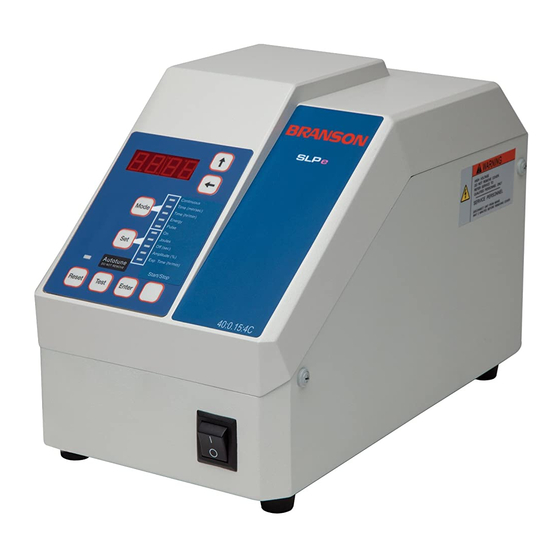
Chapter 2: Introduction to the SLPt Cell Disruptor Controls and Commands The digital controls on the SLPt Cell disruptor allow for accuracy and repeatability of control settings. Application parameters are entered into the power supply through the keypad on the front panel of the unit. External signals are initiated via J2 (9 pin) connector on the back of the power supply. - Page 17 SLPt Cell Disruptor Chapter 2: Introduction to the SLPt Cell Disruptor User Manual Controls and Commands Figure 2.2 SLPt Cell Disruptor Front-panel Controls 88:88 Continuous Time(min/sec) Mode Time(hr/min) Pulse Off(sec) Amplitude(%) ExpTime(hr/min) Autotune Start/Stop DO NOT REMOVE Reset Test Enter Some functions of the SLPt Cell disruptor can be controlled through the external input connected located on the rear of the unit.
-
Page 18: Slpt Cell Disruptor Keypad/Display Description
Chapter 2: Introduction to the SLPt Cell Disruptor Controls and Commands 2.2.1 SLPt Cell Disruptor Keypad/Display Description LED Display A 4 digit LED numeric display is located on the front panel. It is controlled by the Left and Up arrow keys located adjacently on the membrane keypad, and are used to respectively select and increment the selected digit. -
Page 19: Back Panel Connections
SLPt Cell Disruptor Chapter 2: Introduction to the SLPt Cell Disruptor User Manual Controls and Commands Left Arrow Key The Left Arrow key selects from right to left, causing each digit in turn to blink, and wraps back to the right. The blinking digit is available to increment using the Up Arrow key. -
Page 20: System Features
• User External Input, provides ability to remote start, seek and overload Alarm Reset. Also can monitor Weld On, Ready and Alarm For additional feature information, please contact your Branson representative. 100-214-252 Rev. A DOC EXPIRES 12PM 9/16/2007. Article or Material must comply with the requirements... -
Page 21: Chapter 3: Delivery And Handling
SLPt Cell Disruptor Chapter 3: Delivery and Handling User Manual Delivery and Handling Chapter 3: Delivery and Handling 3.1 Delivery and Handling The SLPt Cell Disruptor has no special handling constraints. On receipt of your SLPt, take the following steps: Inspect the carton for signs of damage. - Page 22 Chapter 3: Delivery and Handling Delivery and Handling For Your Notes 100-214-252 Rev. A DOC EXPIRES 12PM 9/16/2007. Article or Material must comply with the requirements stipulated by RoHS in its current version of 1/27/03...
-
Page 23: Chapter 4: Installation And Setup
SLPt Cell Disruptor Chapter 4: Installation and Setup User Manual Installation Checklist Chapter 4: Installation and Setup Installation Checklist - - - - - - - - - - - - - - - - - - - - - - -4 - 1 System Block Diagram - - - - - - - - - - - - - - - - - - - - - -4 - 2 System Component Description - - - - - - - - - - - - - - - - -4 - 2 4.3.1... -
Page 24: System Block Diagram
Chapter 4: Installation and Setup System Block Diagram 4.2 System Block Diagram The block diagram shows the relative interaction of the components of a SLPt Cell Disruptor system. The items inside the bold outline are found in the SLPt Cell Disruptor unit. Some elements shown are optional. Filter Harmonics 500 W... -
Page 25: Tools
101-063-176 4.3.2 Tools Three sizes of microtips are available for use with Sonifier SLPt units. While other tools may be available for use with the SLPt Cell Disruptors, the primary tool is a microtip. Microtips are useful for processing smaller volumes, particularly where higher amplitudes are required. - Page 26 Chapter 4: Installation and Setup System Component Description The tapered microtip attaches directly to the converter. The tapered tip is recommended for applications such as spores, fungi, yeast, muscle, and connective tissue. Excellent results can be obtained on volumes ranging from 3 to 20 ml in a relatively short period of time. As the diameter of the tip decreases, the ampli- tude increases often requiring lower power settings for small volumes.
- Page 27 SLPt Cell Disruptor Chapter 4: Installation and Setup User Manual System Component Description Soundproof Enclosure Although ultrasound is above the normal range of human hearing, audible sound sometimes occurs when liquids are treated ultrasonically, especially due to cavitation produced by ultrasonic vibration. The Sound- proof Enclosure can be used to reduce this to an acceptable level.
-
Page 28: Assembling The Equipment
Chapter 4: Installation and Setup Assembling the Equipment 4.4 Assembling the Equipment The SLPt Cell Disruptor unit is pre-assembled and requires no special tools, however other components must be connected to the unit in order for the system to operate. Some assembly of the ultrasonic horn is required, as described in the following sections. -
Page 29: Connecting Microtips, And Converters
SLPt Cell Disruptor Chapter 4: Installation and Setup User Manual Assembling the Equipment 4.4.2 Connecting Microtips, and Converters Connecting the Microtip to the Converter To connect the microtip to the converter, take the following steps: Step Action Clean the contacting surfaces of the converter and microtip, and remove any foreign matter from the threaded stud and threaded hole. -
Page 30: Input Power Requirements
Chapter 4: Installation and Setup Input Power Requirements 4.5 Input Power Requirements The input power requirements for the SLPt Cell Disruptor are: • 117 VAC, 50/60 Hz (North American model) • 200-245 VAC, 50/60 Hz (Export models only) The SLPt Cell Disruptor is equipped with an IEC-type power cord connector. The unit requires a single- phase, three-wire, 50/60 Hz power source. -
Page 31: User I/O Connection
SLPt Cell Disruptor Chapter 4: Installation and Setup User Manual Guards and Safety Equipment 4.6.2 User I/O Connection The SLPt Cell Disruptor is equipped with a standard external connection to allow you to design and connect your own custom interface for controlling the unit. The User I/O interface can be useful when you need to activate the Sonifier remotely, for example, when the operator must start and stop the unit from another room for safety reasons. -
Page 32: Ultrasonic Test
Chapter 4: Installation and Setup Ultrasonic Test 4.8 Ultrasonic Test The Test button on the front panel of the SLPt Cell Disruptor is used to verify that the unit is functioning (providing ultrasonic energy to the Converter and Horn). Later, you can run another test on the system for your particular experiment (described in 5.3 System Performance Benchmark). -
Page 33: Chapter 5: Technical Specifications
SLPt Cell Disruptor Chapter 5: Technical Specifications User Manual Technical Specifications Chapter 5: Technical Specifications Technical Specifications - - - - - - - - - - - - - - - - - - - 5-1 Physical Description - - - - - - - - - - - - - - - - - - - - - 5-2 System Performance Benchmark - - - - - - - - - - - - - - - 5-3 5.1 Technical Specifications The following table outlines the technical specifications for the Digital Sonifier:... -
Page 34: Physical Description
Chapter 5: Technical Specifications Physical Description 5.2 Physical Description The following table outlines the physical characteristics of the Digital Sonifier. Converter Weight with cable 1.1 lbs. (0.5kg) Converter Length 5”, (127mm) Converter Diameter 1.5” (38mm) Converter to Microtip Stud M8 x 1.25 Horn Tip Diameters 0.091, 0.125 and 0.250 (2.3 –... -
Page 35: System Performance Benchmark
SLPt Cell Disruptor Chapter 5: Technical Specifications User Manual System Performance Benchmark 5.3 System Performance Benchmark Each application and system configuration is slightly different. System performance will vary when you change setup parameters and if your tools change. This can affect the results of your experiments. Creating a benchmark of your initial setup and performance can be useful at a later date in identifying a change in performance, and can also help in recreating your exact initial setup. - Page 36 Chapter 5: Technical Specifications System Performance Benchmark Branson SLPt Cell Disruptor Setup Form Make a copy of this form and use it to record a benchmark for your system’s setup. Date: Operator: Experiment/Solution: ________________________________ Digital Sonifier Model: SLPt 120 Volt...
-
Page 37: Chapter 6: Operation
SLPt Cell Disruptor Chapter 6: Operation User Manual Front Panel Controls Chapter 6: Operation Front Panel Controls - - - - - - - - - - - - - - - - - - - - - - - - - - -6 - 2 6.1.1 Power Switch - - - - - - - - - - - - - - - - - - - - - - - - - - - - -6 - 2 6.1.2... -
Page 38: Membrane Keypad
Chapter 6: Operation Front Panel Controls 6.1.2 Membrane Keypad The membrane keypad on the front panel of the SLPt Sonifier allows you to enter parameters for both Sys- tem Setup and Operation of the unit. Figure 6.1 SLPt Cell Disruptor Front Panel Display Membrane 88:88 Continuous Time(min/sec) - Page 39 SLPt Cell Disruptor Chapter 6: Operation User Manual Front Panel Controls Digital LED Display: Displays parameters. All parameters to be set are viewed on this display. During a weld cycle, % Peak Power is displayed, and the lower 1A and upper half 1B of a colon will blink respectively to indicate sonics on and off.
-
Page 40: Rear Inputs And Connections
Chapter 6: Operation Rear Inputs and Connections 6.2 Rear Inputs and Connections 1. Power input receptacle with fuse holder 2. RF output cable connector, J1 3. User Input connector, J2 Refer to Chapter 2, Figure 2.3 for a detailed rear view drawing. Figure 6.2 User Input J2 Pin Connection Key Feature... -
Page 41: Control Menu
SLPt Cell Disruptor Chapter 6: Operation User Manual System Modes Pulse Start (PS) To set the method of trigger switch duration, select Off (0) if you desire to hold the trigger signal throughout the duration of the process cycle. If the start signal is lost, the cycle is aborted and no alarm is produced. Select On (1) if you wish to start the cycle with a pulse (minimum duration of 10ms). - Page 42 Chapter 6: Operation System Modes The following table shows the relationship between the Mode and Set (parameter) Table 6.2 Mode Set (parameter) Continuous Amplitude Time (min/sec) On, Off, Amplitude Time (hr/min) On, Off, Amplitude Time (min/sec) with Pulse On, Off, Amplitude, Exp Time Time (hr/min) with Pulse On, Off, Amplitude, Exp Time An error will generate 2 beeps, entering an illegal value will generate 3 beeps.
-
Page 43: Operational Sequence
SLPt Cell Disruptor Chapter 6: Operation User Manual Operational Sequence 6.4 Operational Sequence NOTE While Configuration Menu parameters can be specified each time the unit is powered up, the default factory settings are correct for most applications, and are enabled at power up. If there is a need to re-configure, press and hold the ENTER key (6) while powering up. -
Page 44: Slpt In Time Mode (Either Low, Min/Sec Or High, Hr/Min)
Chapter 6: Operation Operational Sequence 6.4.2 SLPt in Time Mode (Either Low, min/sec or High, hr/min) 1. Turn On power, wait for display (1) to show Ready (rdY). 2. Select Mode (2) > Time (2B). The On (3A), Off (3C), and Amplitude LED’s (3D) will light. 3. -
Page 45: Alarms
Er:OL at this point, call your local Branson representative or send to Bran- son Authorized Service Center for repair. Turn power off and back on. If the mes- sage repeats, call your local Branson rep- Er:rF NOVRAM Failure resentative or send to Branson Authorized Service Center for repair. - Page 46 Chapter 6: Operation Alarms 6-10 100-214-252 Rev. A DOC EXPIRES 12PM 9/16/2007. Article or Material must comply with the requirements stipulated by RoHS in its current version of 1/27/03...
-
Page 47: Chapter 7: Maintenance
SLPt Cell Disruptor Chapter 7: Maintenance User Manual Maintenance and Troubleshooting Chapter 7: Maintenance Maintenance and Troubleshooting - - - - - - - - - - - - - - - -7 - 1 Reconditioning the Converter/Tool Interface - - - - - - - - - - -7 - 2 7.2.1 Refacing the Mating Surfaces- - - - - - - - - - - - - - - - - -7 - 3 Troubleshooting Charts - - - - - - - - - - - - - - - - - - - - - -7 - 4... -
Page 48: Reconditioning The Converter/Tool Interface
Chapter 7: Maintenance Reconditioning the Converter/Tool Interface Power Output Loss There are several conditions that can cause a decrease in or loss of power output, including • operating with a faulty power supply or poor electrical connection • operating with a loose tool-converter connection, and •... -
Page 49: Refacing The Mating Surfaces
SLPt Cell Disruptor Chapter 7: Maintenance User Manual Troubleshooting Charts 7.2.1 Refacing the Mating Surfaces NOTE Never clean the Converter or Horn mating surfaces with a buffing wheel. Disassemble the Converter / Tool and wipe the mating surfaces with a clean cloth or paper towel. Examine all mating surfaces. - Page 50 Chapter 7: Maintenance Troubleshooting Charts Table 7.1 System Trouble Analysis Chart Symptom Probable Cause Corrective Action Main power fuse fails or • Cordset has failed • Replace cordset circuit breaker trips when • Power Switch has failed. system is plugged into •...
- Page 51 SLPt Cell Disruptor Chapter 7: Maintenance User Manual Troubleshooting Charts Table 7.1 System Trouble Analysis Chart Symptom Probable Cause Corrective Action • Tighten or replace • Tool is loose or has failed defective tool • Converter cable connection • Tighten converter cable Ultrasonic power is is loose or has failed on back of Sonifier...
-
Page 52: Interconnect Diagram
Chapter 7: Maintenance Interconnect Diagram 7.4 Interconnect Diagram 100-214-252 Rev. A DOC EXPIRES 12PM 9/16/2007. Article or Material must comply with the requirements stipulated by RoHS in its current version of 1/27/03... - Page 53 Benchmark for Setup............... 5 - 3 Benchmark, performance ..............5 - 3 Benchmark, saving................5 - 3 Block Diagram, System ..............4 - 2 Branson how to contact ................1 - 6 Component Description, System............. 4 - 2 Components standard ..................4 - 2 Connecting Microtips, and Converters ..........
- Page 54 Front Panel Controls ............... 6 - 1 Fuse ....................4 - 8 Guards and Safety Equipment ............4 - 9 How to Contact Branson ..............1 - 6 Input Power Requirements.............. 4 - 8 Installation and Setup..............4 - 1 Installation Checklist................
- Page 55 SLPt Cell Disruptor Instruction Manual Operation..................6 - 1 Out-of-range parameters..............6 - 7 out-of-range parameters..............6 - 6 Overview ..................2 - 1 Physical Description ................ 5 - 2 Power Output Loss................7 - 2 Power Requirements input ................... 4 - 8 Power Switch...................
- Page 56 Technical Specifications for the Digital Sonifier ......5 - 1 Timed Mode ..................6 - 4 Tip Erosion ..................7 - 1 Troubleshooting................7 - 1 Ultrasonic Test ................4 - 10 User I/O ................... 4 - 9 Warranty statement ................. 1 - 5 Workplace setting up..................
Need help?
Do you have a question about the Sonifier SLPt and is the answer not in the manual?
Questions and answers