Sign In
Upload
Download
Table of Contents
Contents
Add to my manuals
Delete from my manuals
Share
URL of this page:
HTML Link:
Bookmark this page
Add
Manual will be automatically added to "My Manuals"
Print this page
×
Bookmark added
×
Added to my manuals
Manuals
Brands
CYBEX Manuals
Fitness Equipment
SPARC
Owner's manual
CYBEX SPARC Owner's Manual
Hide thumbs
1
2
3
4
Table Of Contents
5
6
7
8
9
10
11
12
13
14
15
16
17
18
19
20
21
22
23
24
25
26
27
28
29
30
31
32
33
34
35
36
37
38
page
of
38
Go
/
38
Contents
Table of Contents
Bookmarks
Table of Contents
Table of Contents
Safety
Safety Instructions
Warnings and Cautions
Label Placement
Assembly
Specifications - 50A1
Top View - 50A1
Choosing and Preparing Site
Environment
Assembly Procedure
Setup
Calibrate Resistance Level
Testing Operation
Operation
Individual Human Power Versus Mechanical Power
Intended Use
Terms Used
User Controls
Incline Lever
Resistance Lever
Mount and Dismount
Quick Operation Guide
Detailed Operation Guide
Results
How Power Input Versus Displayed Value Is Calculated
Maintenance
Warnings
Clean Unit
Batteries
Service Schedule
Customer Service
Product Registration
Contacting Service
Ordering Parts
Return Material Authorization (RMA)
Damaged Parts
Advertisement
Quick Links
1
Detailed Operation Guide
2
Batteries
Download this manual
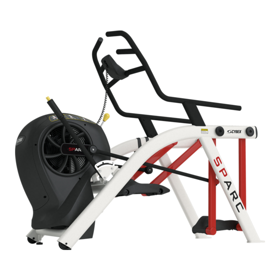
SPARC
50A1 Owner's Manual
Part Number
50A1-999-4 AC
®
Table of
Contents
Previous
Page
Next
Page
1
2
3
4
5
Advertisement
Table of Contents
Need help?
Do you have a question about the SPARC and is the answer not in the manual?
Ask a question
Questions and answers
Related Manuals for CYBEX SPARC
Fitness Equipment CYBEX Structure ST-HR Assembly Instructions Manual
(46 pages)
Fitness Equipment CYBEX VR Owner's Manual
Cybex vr exercise equipment owner’s manual (18 pages)
Fitness Equipment CYBEX 11050-999-4 A Owner's Manual
Cybex eagle leg extension. strength systems (32 pages)
Fitness Equipment CYBEX 50A1 Owner's Manual
(38 pages)
Fitness Equipment CYBEX Arc Trainer 610A Service Manual
(43 pages)
Fitness Equipment CYBEX MG 500 Owner's And Service Manual
Multi-gym (198 pages)
Fitness Equipment CYBEX FT 360 Owner's And Service Manual
Functional trainer (90 pages)
Fitness Equipment CYBEX Bravo Press Owner's Manual
(26 pages)
Fitness Equipment CYBEX Arc Trainer 770A Owner's Manual
Arc trainer cardiovascular systems (96 pages)
Fitness Equipment CYBEX 700C Owner's Manual
(40 pages)
Fitness Equipment CYBEX Arc Trainer 750A Owners Manual And Service Manual
Cardiovascular systems (78 pages)
Fitness Equipment CYBEX VR2 Owner's And Service Manual
(231 pages)
Fitness Equipment CYBEX Bravo 8800 Owner's Manual
(27 pages)
Fitness Equipment CYBEX Bravo Series Owner's Manual
(29 pages)
Fitness Equipment CYBEX Bravo 8840 Owner's Manual
Strength systems (34 pages)
Fitness Equipment CYBEX Arc Trainer 630A Service Manual
Cardiovascular systems (70 pages)
This manual is also suitable for:
50a1
Table of Contents
Print
Rename the bookmark
Delete bookmark?
Delete from my manuals?
Login
Sign In
OR
Sign in with Facebook
Sign in with Google
Upload manual
Upload from disk
Upload from URL


Need help?
Do you have a question about the SPARC and is the answer not in the manual?
Questions and answers