
Related Manuals for CYBEX Arc Trainer 630A


Summary of Contents for CYBEX Arc Trainer 630A
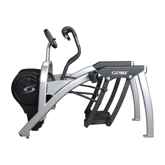
- Page 1 ® Cybex Arc Trainer 630A Service Manual Cardiovascular Systems Part Number 630A-901 B www.cybexinternational.com...
- Page 3 Cybex International, Inc. DISCLAIMER: Cybex International, Inc. makes no representations or warranties regarding the contents of this manual. We reserve the right to revise this document at any time or to make changes to the product described within it without notice or obligation to notify any person of such revisions or changes.
- Page 5 Cybex Arc Trainer 630A Service Manual About This Manual the following: To contact Cybex with comments about this manual you may send email to FCC Compliance Information ! WARNING: Changes or modifications to this unit not expressly approved by the party responsible for compliance could void the user’s authority to operate the...
- Page 7 Warnings ......2-1 ..2-1 Cleaning Your Arc Trainer 630A ..2-2 ....2-3 Lubrication .
- Page 9 Seek a qualified electrician to perform any modifications to the cord or plug. Cybex is not responsible for injuries or damages as a result of cord or plug modification.
- Page 10 Cybex Arc Trainer 630A Service Manual Important Safety Instructions ! DANGER: To reduce the risk of electric shock, always unplug this unit from the electrical outlet immediately after using it and before cleaning it. ! WARNING: Serious injury could occur if these precautions are not observed. To reduce the risk...
- Page 11 Cybex Arc Trainer 630A Service Manual Facility Safety Precautions service from a qualified technician. NOTE: It is the sole responsibility of the user/owner or facility operator to ensure that regular maintenance is performed. Arc Trainers containing the A/V options Safety...
- Page 12 Cybex Arc Trainer 630A Service Manual Safety Page 1-4...
- Page 13 Warning Decals Carefully read and understand the following before using the unit: NOTE: To replace any worn or damaged decals, fax orders to 508-533-5183 or contact Cybex Customer Service at 888-462-9239. If you live outside of the USA, call 508-533-4300.
- Page 14 Cybex Arc Trainer 630A Service Manual Underneath Access Cover 630A-316 SERIOUS INJURY COULD OCCUR IF THESE PRECAUTIONS ARE NOT OBSERVED High voltage is present under this shield. This shield should only be removed by a qualified service technician. Keep wet items away from inside parts.
- Page 15 Arc Trainer 620A/629A Kits Covers: Crank Cover 600AK023 Front Access Cover 600AK024 Pivot Cover, Left Hand 610AK004 Pivot Cover, Right Hand 610AK005 Shroud, Left 600AK025 Shroud, Right 600AK027 Front End: Elevation Motor Tube 600AK004 Lower Pulley 600AK014 Primary Drive 16 Rib Belt 600AK020 Pulley and Crank Shaft 600AK002...
- Page 16 This page intentionally left blank. Service Page 4-18...
- Page 17 Arc Trainer ® and its mark are registered trademarks of Cybex International, Inc. 10 Trotter Drive Medway, MA 02053 • 508-533-4300 • FAX 508-533-5183 • www.cybexinternational.com • techhelp@cybexintl.com techpubs@cybexintl.com • Copyright © 2008, Cybex International, Inc. All rights reserved • 600A-345 C • March 2008...
- Page 18 This page intentionally left blank.
- Page 19 Arc Trainer ® and its mark are registered trademarks of Cybex International, Inc. 10 Trotter Drive Medway, MA 02053 • 508-533-4300 • FAX 508-533-5183 • www.cybexinternational.com • techhelp@cybexintl.com techpubs@cybexintl.com • Copyright © 2008, Cybex International, Inc. All rights reserved • 600A-356 A • March 2008...
- Page 20 This page intentionally left blank.
- Page 21 Arc Trainer ® and its mark are registered trademarks of Cybex International, Inc. 10 Trotter Drive Medway, MA 02053 • 508-533-4300 • FAX 508-533-5183 • www.cybexinternational.com • techhelp@cybexintl.com techpubs@cybexintl.com • Copyright © 2008, Cybex International, Inc. All rights reserved • 610A-365 B • March 2008...
- Page 22 This page intentionally left blank.
- Page 23 ® Arc Trainer Shroud Installation Instructions Kit No. 600AK025 - Left Shroud Kit 600AK027 - Right Shroud Kit NOTE: This instruction sheet describes how to replace the 4. Elevate the unit and disconnect the power shrouds in the Arc Trainer 600A/610A. source.
- Page 24 Arc Trainer ® and its mark are registered trademarks of Cybex International, Inc. 10 Trotter Drive Medway, MA 02053 • 508-533-4300 • FAX 508-533-5183 • www.cybexinternational.com • techhelp@cybexintl.com techpubs@cybexintl.com • Copyright © 2008, Cybex International, Inc. All rights reserved • 600A-357 B • March 2008...
- Page 25 ® Arc Trainer Elevation Motor Tube Replacement Installation Instructions Kit No. 600AK004 ! WARNING: Do not touch components on the TOOLS REQUIRED lower board. A charge can remain after unplugging the power cord • Phillips head screwdriver • 9/16” Open end wrench and turning off the unit.
- Page 26 Arc Trainer ® and its mark are registered trademarks of Cybex International, Inc. 10 Trotter Drive Medway, MA 02053 • 508-533-4300 • FAX 508-533-5183 • www.cybexinternational.com • techhelp@cybexintl.com techpubs@cybexintl.com • Copyright © 2008, Cybex International, Inc. All rights reserved • 600A-307 A • March 2008...
- Page 27 ® Arc Trainer 600A/610A Lower Pulley Installation Instructions Kit No. 600AK014 NOTE: This instruction sheet describes how to replace 4. Remove the access cover. the lower pulley on the Arc Trainer 600A/610A. A. Using a Phillips head screwdriver, remove the four screws and four washers securing the TOOLS REQUIRED access cover.
- Page 28 Arc Trainer ® and its mark are registered trademarks of Cybex International, Inc. 10 Trotter Drive Medway, MA 02053 • 508-533-4300 • FAX 508-533-5183 • www.cybexinternational.com • techhelp@cybexintl.com techpubs@cybexintl.com • Copyright © 2008, Cybex International, Inc. All rights reserved • 600A-317 B • March 2008...
- Page 29 ® Arc Trainer 600A/610A Primary Drive 16 Rib Belt Installation Instructions Kit No. 600AK020 NOTE: This instruction sheet describes how to replace ! WARNING: Disconnect the power cord before the primary drive 16 rib belt on the Arc Trainer continuing this procedure. Keep wet items away from inside parts of the 600A/610A.
- Page 30 6. Remove the side covers. Idler Screw Pulley A. Remove Gasket Washer the six screws and Washer/Bolt six washers securing each side Figure 7 cover in place. See Side 9. Remove HHCS on lower pulley. Figure 4. Cover A. Using a 7/16” socket wrench with a 3” B.
- Page 31 11. Crank shaft assembly pillow block bolts. D. Turn each HHCS in a couple of turns by hand. A. Using a 9/16” socket wrench and a 9/16” open E. Place secondary drive belt on the (secondary wrench remove the two bolts, four washers and pulley and then on the lower pulley.
- Page 32 Arc Trainer ® and its mark are registered trademarks of Cybex International, Inc. 10 Trotter Drive Medway, MA 02053 • 508-533-4300 • FAX 508-533-5183 • www.cybexinternational.com • techhelp@cybexintl.com techpubs@cybexintl.com • Copyright © 2008, Cybex International, Inc. All rights reserved • 600A-342 C • March 2008...
- Page 33 ® Arc Trainer Pulley and Crank Shaft Installation Instructions Kit No. 600AK002 NOTE: This instruction sheet describes how to replace the 3. Elevate the unit and disconnect the power crank shaft in the 600A/610A Arc Trainer. source. A. Elevate the unit to a minimum of level 7 incline. TOOLS REQUIRED B.
- Page 34 6. Remove the NOTE: Tension is now released. Leave lower pivot side covers. assembly in place. Screw ! WARNING: Do not touch components on the A. Remove Gasket Washer lower board. A charge can remain the six after unplugging the power cord and screws and turning off the unit.
- Page 35 12. Attach the crank shaft assembly. NOTE: The new bearings have been pre-assembled on the new crank shaft assembly and are not adjustable. Standoff (4) A. Place the assembly into the primary belt and slide the pins into the holes on the frame. See Figure 11.
- Page 36 Arc Trainer ® and its mark are registered trademarks of Cybex International, Inc. 10 Trotter Drive Medway, MA 02053 • 508-533-4300 • FAX 508-533-5183 • www.cybexinternational.com • techhelp@cybexintl.com techpubs@cybexintl.com • Copyright © 2008, Cybex International, Inc. All rights reserved • 600A-302 L • March 2008...
- Page 37 ® Arc Trainer Rear Foot Plate Arms Installation Instructions Kit No. 610AK010 - Left Rear Foot Plate Arm Kit 610AK011 - Right Rear Foot Plate Arm Kit NOTE: This instruction sheet describes how to replace 4. Install the new foot plate arm the front foot plate arms in the Arc Trainer 610A.
- Page 38 Arc Trainer ® and its mark are registered trademarks of Cybex International, Inc. 10 Trotter Drive Medway, MA 02053 • 508-533-4300 • FAX 508-533-5183 • www.cybexinternational.com • techhelp@cybexintl.com techpubs@cybexintl.com • Copyright © 2008, Cybex International, Inc. All rights reserved • 610A-368 A • March 2008...
- Page 39 Arc Trainer ® and its mark are registered trademarks of Cybex International, Inc. 10 Trotter Drive Medway, MA 02053 • 508-533-4300 • FAX 508-533-5183 • www.cybexinternational.com • techhelp@cybexintl.com techpubs@cybexintl.com • Copyright © 2008, Cybex International, Inc. All rights reserved • 610A-393 B • March 2008...
- Page 40 Arc Trainer ® and its mark are registered trademarks of Cybex International, Inc. 10 Trotter Drive Medway, MA 02053 • 508-533-4300 • FAX 508-533-5183 • www.cybexinternational.com • techhelp@cybexintl.com techpubs@cybexintl.com • Copyright © 2008, Cybex International, Inc. All rights reserved • 610A-394 B • March 2008...
- Page 41 Arc Trainer ® and its mark are registered trademarks of Cybex International, Inc. 10 Trotter Drive Medway, MA 02053 • 508-533-4300 • FAX 508-533-5183 • www.cybexinternational.com • techhelp@cybexintl.com techpubs@cybexintl.com • Copyright © 2008, Cybex International, Inc. All rights reserved • 610A-405 A • March 2008...
- Page 42 This page intentionally left blank.
- Page 43 ® Arc Trainer Main Frame Assembly Installation Instructions Kit No. 610AK019-4 Kit No. 630AK019-4 NOTE: This instruction sheet describes how to replace the main frame assembly in the Arc Trainer 610A. Upper Display Cable Tools Required Console Lower • 3/16” Allen wrench •...
- Page 44 B. Remove handle linkage rod and set aside along B. Carefully remove the left foot plate arm with hardware removed in step 6A. NOTE: These assembly and set aside. See Figure 5. will be attached to the new frame later. 9.
- Page 45 12. Remove right foot plate arm assembly and right pivot cover. A. Repeat steps 7-9. See Figure 5. 13. Install right foot plate arm assembly and right Screws pivot cover. A. Repeat steps 10 and 11. See Figure 5. 14. Remove the access cover. Washer Washer A.
- Page 46 19. Unplug and remove the display cable. B. Using a 9/16” socket and open end wrench, attach four washers and nuts (removed in step A. Unplug the display cable from the control board 20B) to HHCS and tighten securing two drive and remove cable from drive frame assembly.
- Page 47 Arc Trainer ® and its mark are registered trademarks of Cybex International, Inc. 10 Trotter Drive Medway, MA 02053 • 508-533-4300 • FAX 508-533-5183 • www.cybexinternational.com • techhelp@cybexintl.com techpubs@cybexintl.com • Copyright © 2008, Cybex International, Inc. All rights reserved • 610A-404 B • March 2008...
- Page 48 This page intentionally left blank.
- Page 49 Arc Trainer ® and its mark are registered trademarks of Cybex International, Inc. 10 Trotter Drive Medway, MA 02053 • 508-533-4300 • FAX 508-533-5183 • www.cybexinternational.com • techhelp@cybexintl.com techpubs@cybexintl.com • Copyright © 2008, Cybex International, Inc. All rights reserved • 600A-309 B • March 2008...
- Page 50 This page intentionally left blank.
- Page 51 Arc Trainer ® and its mark are registered trademarks of Cybex International, Inc. 10 Trotter Drive Medway, MA 02053 • 508-533-4300 • FAX 508-533-5183 • www.cybexinternational.com • techhelp@cybexintl.com techpubs@cybexintl.com • Copyright © 2008 CYBEX International, Inc. All rights reserved • 600A-312 B • March 2008...
- Page 52 This page intentionally left blank.
- Page 53 Arc Trainer ® and its mark are registered trademarks of Cybex International, Inc. 10 Trotter Drive Medway, MA 02053 • 508-533-4300 • FAX 508-533-5183 • www.cybexinternational.com • techhelp@cybexintl.com techpubs@cybexintl.com • Copyright © 2008, Cybex International, Inc. All rights reserved • 610A-387 B • March 2008...
- Page 54 This page intentionally left blank.
- Page 55 ® Arc Trainer Heart Rate Grip Installation Instructions Kit No. 620AK002 without drill bit 620AK007 with drill bit A. With a flat head screwdriver, carefully pry NOTE: This instruction sheet describes how to install off each metal sensor plate from grip and the heart rate grips on the 620A and 629A Arc disconnect both heart rate wires.
- Page 56 Arc Trainer ® and its mark are registered trademarks of Cybex International, Inc. 10 Trotter Drive Medway, MA 02053 • 508-533-4300 • FAX 508-533-5183 • www.cybexinternational.com • techhelp@cybexintl.com techpubs@cybexintl.com • Copyright © 2008, Cybex International, Inc. All rights reserved • 620A-323 D • March 2008...
- Page 57 ® Arc Trainer Handle Bar Installation Instructions Kit No. 620AK005 NOTE: This instruction sheet describes how to replace the handle bar in the Arc Trainer 620A. Tools Required • 7/32” Allen wrench 1. Read and understand all instructions thoroughly (D)/ before installing this kit.
- Page 58 Arc Trainer ® and its mark are registered trademarks of Cybex International, Inc. 10 Trotter Drive Medway, MA 02053 • 508-533-4300 • FAX 508-533-5183 • www.cybexinternational.com • techhelp@cybexintl.com techpubs@cybexintl.com • Copyright © 2008, Cybex International, Inc. All rights reserved • 620A-326 A • March 2008...
- Page 59 L. A/V bottom membrane (1), SW-19295-4 (NOTE: for English Console only) NOTE: The Power Cable of (F) has a male and female M. Cybex monitor kit (1), EE000005 or EE000007 connector at either end. Make sure the female N. Poster (1), 620A-387 (not shown) end goes to the Monitor (Q) and the male end O.
- Page 60 5. Remove left wheel. Upper Console Display Assembly A. Place a block under the unit as shown in Figure 7. Cable B. Using a 7/16” wrench and a 5/32” Allen wrench, remove the bolt and nut securing the left wheel in place and remove the wheel.
- Page 61 E. Feed cable through to the bottom where wheel was removed. F. Route cable back up through the hole and out through the access hole. See Figure 8. G. Pull rest of cable through the access hole. Ribbon Cable See Figure 8. 7.
- Page 62 B. Insert the RJ-45 cable up through the monitor mount and exit the top. See Figure 17. C. Using a 5/32” Allen wrench, reattach the four BHSCS and four lock washers securing the console to the new console mount. See Figure 6.
- Page 63 14. Attach Console Assembly. B. Remove the back cover from monitor (Q) by pressing the bottom tabs of the cover in and A. Plug the upper display cable into the lower rotating out. See Figure 19 . display cable in the main frame assembly. See Figure 18.
- Page 64 Arc Trainer ® and its mark are registered trademarks of Cybex International, Inc. 10 Trotter Drive Medway, MA 02053 • 508-533-4300 • FAX 508-533-5183 • www.cybexinternational.com • techhelp@cybexintl.com techpubs@cybexintl.com • Copyright © 2008, Cybex International, Inc. All rights reserved • 620A-385 C • March 2008...
- Page 65 ® Arc Trainer Voltage Assembly Kit No. 630AK031 - 110V/60Hz Voltage Assembly Kit Installation Instructions 630AK033 - 220V/50Hz Voltage Assembly Kit 630AK034 - 250V/3A Voltage Assembly Kit 5. Remove the access cover. 630AK035 - 110V/50Hz Voltage Assembly Kit A. Using a Phillips screwdriver, remove the two lower NOTE: This instruction sheet describes how to install the screws (one screw on each side), securing the voltage assembly kit in the Arc 630A.
- Page 66 Cybex International, Inc. 10 Trotter Drive Medway, MA 02053 • 508-533-4300 • FAX 508-533-5183 • www.cybexinternational.com • techhelp@cybexintl.com techpubs@cybexintl.com • Copyright © 2008, Cybex International, Inc. All rights reserved • 630A-326 A • March 2008...
- Page 67 Cybex Arc Trainer 630A Service Manual ADAPTER, SERVICE PROGRAMMING CN-16924 MR-18446 GEARMOTOR,SP ARC 12V DC J102 EC-18267 GRAY CHASSIS 1 CD CARRIER DETECT BATTERY, 12V / 7AHR BROWN 2 RD RECEIVE DATA 12v DC POSITION YELLOW 3 TD TRANSMIT DATA...
- Page 68 Service Page 4-16...
- Page 70 10 Trotter Drive Medway, MA 02053 • 508-533-4300 • FAX 508-533-5183 www.cybexinternational.com • Techhelp@cybexintl.com•techpubs@cybexintl.com...
Need help?
Do you have a question about the Arc Trainer 630A and is the answer not in the manual?
Questions and answers
Can the mainframe of cybex arc trainer model 630a be partially disassembled to allow moving equipment through smaller doorway, then reassembled appropriately?