
Related Manuals for CYBEX Arc Trainer 770A


Summary of Contents for CYBEX Arc Trainer 770A
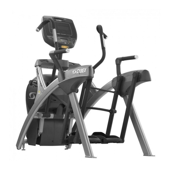
- Page 1 Cybex 770A/770AT Arc Trainer ® Owner’s Manual Cardiovascular Systems Part Number 5770-4 C www.cybexintl.com...
-
Page 2: Table Of Contents
Apple. DISCLAIMER: Cybex International, Inc., makes no representations or warranties regarding the contents of this manual. We reserve the right to revise this document at any time or to make changes to the product described within it without notice or obligation to notify any person of such revisions or changes. -
Page 3: Fcc Compliance Information
Cybex Owner’s Manual FCC Compliance Information Changes or modifications to this unit not expressly approved by the party responsible for compliance could void the user’s authority to operate the equipment! This equipment has been tested and found to comply with the limits for a Class B digital device, pursuant to part 15 of the FCC Rules. -
Page 4: Safety
Cybex Owner’s Manual Safety Read all instructions and warnings before using. Ground and Voltage Information DANGER: Death or serious injury can occur. To avoid death or serious injury the following precautions must be observed. Equipment must be properly grounded. Check with a qualified electrician or service provider to verify the unit is properly grounded. -
Page 5: Important Safety Instructions
• Verify there is enough room for safe access and operation of unit. • Use Cybex AC power adapters only. • Do not use the optional power adapter in damp or wet locations. Do not use the unit if: (1) the unit is plugged into an optional power adapter that has a damaged •... - Page 6 Cybex Owner’s Manual Do not attempt electrical or mechanical repairs. Seek qualified repair personnel when servicing. If • you live in the USA, contact Cybex Customer Service at 888-462-9239. If you live outside the USA, contact Cybex Customer Service at 508-533-4300. •...
- Page 7 Cybex Owner’s Manual • Do not defeat the safety purpose of the polarized or grounding-type plug. A polarized plug has two blades with one wider than the other. A grounding type plug has two blades and a third grounding prong. The wide blade or the third prong is provided for safety. If the provided plug does not fit into outlet, consult an electrician for replacement of the obsolete outlet.
-
Page 8: Warnings And Cautions
508-533-5183 or contact Cybex Customer Service at 888-462-9239. If you are located outside of the USA, call 508-533-4300. For location or part number of labels, see the parts list and exploded-view diagram on the Cybex web site at www.cybexintl.com. -
Page 9: Label Placement
Cybex Owner’s Manual Label Placement 770A-331-4 770A-332-4 1.80 R .12 4 PLACES CAUTION SAFETY YELLOW PMS 108 CAUTION BACKGROUND BLACK TRIANGLE W/ YELLOW EXCLAMATION POINT, 1.25 Moving parts. Moving parts. BLACK LETTERS 18.9 PT ARIAL BLACK FONT Keep hands away Keep hands away when in use. -
Page 10: Assembly
Cybex Owner’s Manual Assembly Specifications - 770A Classification S (Studio) Accuracy Length 76.25” (194 cm) 32” (81 cm) Width Height: 62.5” (159 cm) Weight of 404 lbs (183 kg) Product Shipping 429 lbs (195 kg) Weight Incline Levels 0-20 Resistance... -
Page 11: Specifications - 770At
Cybex Owner’s Manual Specifications - 770AT Classification S (Studio) Accuracy Length 76.25” (194 cm) 36.28” (92 cm) Width Height: 62.5”(159 cm) Weight of 412 lbs. (187 kg.) Product Shipping 437 lbs. (198 kg.) Weight Incline Levels 0-20 Resistance 0-100 Levels Stride Length 24”... -
Page 12: Environment And Storage
Do not use a ground-plug adapter to adapt the 3-prong power cord to a non-grounded electrical outlet. • Use Cybex supplied optional AC power kit only. Consult an electrician with any questions. • Ensure outlets used by this product meet all local and federal building codes. -
Page 13: 770A Assembly Procedure
Cybex Owner’s Manual 770A Assembly Procedure Tools Required • Phillips screwdriver • Stubby Phillips screwdriver • 3/16” Allen wrench (supplied) • 7/32” Allen wrench (supplied) • 9/16” Open end wrench (2) The words “left” and “right” denote the user’s orientation. - Page 14 Cybex Owner’s Manual...
- Page 15 Cybex Owner’s Manual Verify contents of hardware pack See hardware pack listings and hardware pack contents. See Customer Service for contact information if any parts are missing. Item Quantity Part Number Description BK030204 7/32” Allen Wrench HC700430 BHSCS .375-16 x 2.50”...
- Page 16 Cybex Owner’s Manual...
- Page 17 4. Move unit to intended location. 5. Lower rear support legs. Attach 770A console assembly. 1. Place the console into position on the frame. Do not pinch cables while lowering the console. Locknuts (4) Console...
- Page 18 Cybex Owner’s Manual Install coax cable (E3 View Monitor option) 1. Remove four screws securing back cover to the console using a Phillips screwdriver. Back Cover Screws (4) 2. Route coax cable up through console support tube. Console Support Tube...
- Page 19 Cybex Owner’s Manual Install accessory tray base 1. Place the accessory tray in position on the frame and route the iPod cable towards the back of the unit. Do not pinch optional coax cable. Accessory Tray Base iPod Cable Coax Cable...
- Page 20 Cybex Owner’s Manual Install accessory tray bottom Install the grommet to the frame. Frame Grommet Install the accessory tray bottom to the accessory tray base with three screws using a Phillips screwdriver. Accessory Tray Bottom Accessory Tray Base Screw Screws (2)
- Page 21 Cybex Owner’s Manual Install handrails. 1. Remove three locknuts from the left support leg using two 9/16” open end wrenches. Keep the two spacers in place. Left Handle Locknuts (3) Spacers (2) 2. Install the left handle and three locknuts using two 9/16” open end wrenches.
- Page 22 Cybex Owner’s Manual 4. Install the left outer rear cover with five screws using a Phillips screwdriver. Screws (2) Left Outer Rear Cover Screws (3) 5. Install the left top rear cover with five screws using a Phillips screwdriver. Screws (5)
- Page 23 Cybex Owner’s Manual 7. Remove three locknuts from the right support leg using two 9/16” open end wrenches. Keep the two spacers in place. Right Handle Locknuts (3) Spacers (2) 8. Install the right handle and three locknuts using two 9/16” open end wrenches.
- Page 24 Cybex Owner’s Manual 10. Install the right outer rear cover with five screws using a Phillips screwdriver. Screws (2) Right Outer Rear Cover Screws (3) 11. Install the right top rear cover with five screws using a Phillips screwdriver. Right Top Rear Cover Screws (5) 12. Install the right inner and outer collars with two screws using a Phillips screwdriver.
- Page 25 Cybex Owner’s Manual Attach foot pads Have one person lift the unit while a second person places a foot pad under each of the two back feet. Foot Pads (2) Level unit Confirm unit is on a level surface. If not, use a 9/16” open-end wrench to adjust the leveling feet up or down.
-
Page 26: 770At Assembly Procedure
Cybex Owner’s Manual Visually inspect unit 1. Carefully remove any package material from arms and rest of unit. 2. Carefully examine the unit to ensure assembly is correct and complete. 770AT Assembly Procedure Tools Required • Phillips screwdriver • Stubby Phillips screwdriver •... - Page 27 Cybex Owner’s Manual Item Quantity Part Number Description 770A-415 Commercial Arc warranty sheet 770A-416 Consumer Arc warranty sheet 770A-427 Cable, 6’, Coax (E3 View Monitor option)
- Page 28 Cybex Owner’s Manual Verify contents of hardware pack See hardware pack listings and hardware pack contents. See Customer Service for contact information if any parts are missing. Item Quantity Part Number Description Flange Spacer 600A-311 BK030201 3/16” Allen Wrench BK030204 7/32”...
- Page 29 Cybex Owner’s Manual...
- Page 30 Cybex Owner’s Manual Lift and move unit 1. Remove large bolts and shipping supports. Keep package material on linkage arms at this time. This will protect the paint from scratching during assembly. 2. Grasp each rear support leg firmly and lift with one person on each side.
- Page 31 Cybex Owner’s Manual Install coax cable (E3 View Monitor option) 1. Remove four screws securing back cover to the console using a Phillips screwdriver. Back Cover Screws (4) 2. Route coax cable up through console support tube. Console Support Tube...
- Page 32 Cybex Owner’s Manual Install accessory tray base 1. Place the accessory tray in position on the frame and route the iPod cable towards the back of the unit. Accessory Tray Base iPod Cable Coax Cable (E3 View Monitor option) Frame Screws 2. Install the four screws using a Phillips screwdriver.
- Page 33 Cybex Owner’s Manual Install accessory tray bottom Install the grommet to the frame. Frame Grommet Install the accessory tray bottom to the accessory tray base with three screws using a Phillips screwdriver. Accessory Tray Bottom Accessory Tray Base Screw Screws (2)
- Page 34 Cybex Owner’s Manual Install handrails. 1. Remove three locknuts from the left support leg using two 9/16” open end wrenches. Keep the two spacers in place. Left Handle Locknuts (3) Spacers (2) 2. Install the left handle and three locknuts using two 9/16” open end wrenches.
- Page 35 Cybex Owner’s Manual 4. Install the left outer rear cover with five screws using a Phillips screwdriver. Screws (2) Left Outer Rear Cover Screws (3) 5. Install the left top rear cover with five screws using a Phillips screwdriver. Left Top...
- Page 36 Cybex Owner’s Manual 7. Remove three locknuts from the right support leg using two 9/16” open end wrenches. Keep the two spacers in place. Right Handle Locknuts (3) Spacers (2) 8. Install the right handle and three locknuts using two 9/16” open end wrenches.
- Page 37 Cybex Owner’s Manual 10. Install the right outer rear cover with five screws using a Phillips screwdriver. Screws (3) Right Outer Rear Cover Screws (3) 11. Install the right top rear cover with five screws using a Phillips screwdriver. Right Top Rear Cover Screws (5) 12. Install the right inner and outer collars with two screws using a Phillips screwdriver.
- Page 38 Cybex Owner’s Manual Remove left and right handle assembly The left and right handle assemblies are shipped in rotated positions. The handle assemblies must be removed and rotated 180 degrees for proper setup and assembly. Shipping Position 1. Remove a screw and washer from the left handle assembly using two 7/32” Allen wrenches.
- Page 39 Cybex Owner’s Manual 7. Remove a screw and washer from the right handle assembly using two 7/32” Allen wrenches. Screw Washer Right Handle Pivot Pin Assembly 8. Slide pivot pin assembly out and remove right handle assembly. 9. Rotate right handle assembly 180 degrees.
- Page 40 Cybex Owner’s Manual Install right linkage rod 1. Pivot right handle assembly up and slide right linkage rod onto right arm. Linkage Rod Flange Right Linkage Spacer Washer Loctite Screw Right Arm 2. Place a drop of Loctite onto the screw.
- Page 41 Cybex Owner’s Manual Connect contact heart rate cable 1. Plug right heart rate cable into main frame socket. Right Side Main Frame Shown Socket Heart Rate Wire Position plug so handle does not rub cable during operation. 2. Plug left heart rate cable into main frame socket.
- Page 42 Cybex Owner’s Manual Level unit Confirm unit is on a level surface. If not, use a 9/16” open-end wrench to adjust the leveling feet up or down. Leveling Feet Install coax cable (E3 View Monitor option) Install 6’ coax cable to the coax cable connector in base of unit.
-
Page 43: Setup
Initial setup Perform this procedure during the installation of the unit. Once complete, refer to Setup Options below. 1. Press the Cybex logo icon to display the Access Toolbox and Lock Screen options. 2. Press the Access Toolbox icon to display the Access to Toolbox login screen. - Page 44 Cybex Owner’s Manual Setup options Enter setup options. 1. Press the Cybex logo icon to display the Access Toolbox and Lock Screen options. 2. Press the Access Toolbox icon to display the Access to Toolbox login screen. 3. Enter the sequence: 4. Press the Setup icon to display the setup menu.
-
Page 45: A/V Configuration And Fm Radio . . . . . . . . . . . . . . . . . . . . . . . . . . . . . . 43 Presets
Cybex Owner’s Manual A/V Configuration and FM Radio Presets Setting up the Cybex Wireless Audio Receiver Module for a 770A and 770AT requires four steps: Determine the type of transmitter used (MYE 900MHz, Broadcast Vision 863MHz, etc. or TV FM). - Page 46 Cybex Owner’s Manual 7. Tap Setup at the main Toolbox screen. 8. Tap Scroll Right to navigate to the A/V Device icon. 9. Tap A/V Device. 10. Tap Device Installed to select “Wireless TV” if not set. 11. Tap Toolbox to return to the Toolbox screen.
- Page 47 Cybex Owner’s Manual If no TV numbers appear, no UHF transmitters were discovered. Verify the UHF transmitters are powered on and set to their respective TV numbers (1,2,3, etc.) or toggle the Near/Far setting and re- scan. Review channels 1. Tap Up or Down to listen to available channels with the headphones.
- Page 48 Cybex Owner’s Manual 5. Repeat procedure to add all TV FM channels. 6. Press Toolbox to exit setup when all the TV’s FM transmitter then Home frequencies have a TV number. Transmitter setup complete. 7. Proceed to Add FM Radio Stations (optional).
- Page 49 The goal is for a volume setting of 10 on the unit to be the same for all TV and FM channels. 7. Repeat procedure for all TV’s. Using the Cybex Wireless Audio Receiver 1. Plug headphones into headphone jack. 2. Begin striding and press the QUICK START icon.
-
Page 50: E3 View Monitor Controls
Cybex Owner’s Manual E3 View Monitor Controls The CardioTouch screen is used to perform all setup operations for the E3 View Monitor. CardioTouch screen functions Wrench Icon Return to Toolbox home Go to Setup home screen Next Moves forward in Setup menu to next screen... -
Page 51: E3 View Monitor Setup
Cybex Owner’s Manual E3 View Monitor Setup Access Setup Screen 1. Tap the Cybex logo icon to display the Access Toolbox and Lock Screen options. 2. Tap the Access Toolbox icon to display the Access to Toolbox login screen. 3. Enter the sequence: 4. Tap the Setup icon to display the setup menu. - Page 52 Cybex Owner’s Manual Picture 1. Tap ▲ or ▼ to select Picture. 2. Tap ► to select access Picture menu. Picture ■ Brightness ■ Contrast ■ Color ■ Tint ■ Color Temperature ► ■ Sharpness ■ Noise Reduction Enabled ■ HDMI Picture ►...
- Page 53 Cybex Owner’s Manual Channels 1. Tap ▲ or ▼ to select Channels. 2. Tap ► to select access Channels menu. ATSC Monitor DVB-T Monitor Channels Channels ■ Signal ■ Auto Program ► Cable STD ■ Auto Program ► ■ Manual Program ►...
- Page 54 Cybex Owner’s Manual Auto Program (ATSC Monitor) 1. Tap ▼ to select Auto Program. 2. Tap ► to enter the menu. 3. Tap ▲ or ▼ to select Mode. ATSC Monitor Auto Program ■ Mode Analog Only ■ Channel Sequence Interleave A + D ■...
- Page 55 Cybex Owner’s Manual 13. Tap the icon to list programmed channels. 14. Tap the Setup icon to return to SETUP MODE menu. Auto Program (DVB-T Monitor) 1. Tap ▼ to select Auto Program. 2. Tap ► to enter the menu. 3. Tap ▲ or ▼ to select Country.
- Page 56 Cybex Owner’s Manual 9. Tap the Setup icon to return to normal TV viewing once auto programming is complete. 10. Tap the icon to list programmed channels. 11. Tap the Setup icon to return to SETUP MODE menu. Manual Program (ATSC and DVB-T) 1. Tap ▼...
- Page 57 Cybex Owner’s Manual Add/Delete Channels (ATSC and DVB-T) 1. Tap ▼ to select Add/Delete Channels. 2. Tap ► to enter the Add/Delete Channels menu. Add/Delete Channels ■ Analog Channel ■ Add/Delete Analog Channel Added ■ Enable/Disable Digital Channel ► Position: ▲ ▼...
- Page 58 Cybex Owner’s Manual Features 1. Tap ▲ or ▼ to select Features. 2. Tap ► to select access Features menu. ATSC Monitor DVB-T Monitor Features Features ■ Power on Captions Mode ■ Power on Subtitles Mode Last Last ■ Digital Mode Time Setup ►...
- Page 59 Cybex Owner’s Manual OSD Language 1. Tap ▲ or ▼ to select OSD Language. 2. Tap ◄ or ► to select language. English, Français or Español. ATSC choices English, Français, Español, Dutch, Danish, Russian, German, and Swedish. DVB-T choices 4. Tap the Setup icon to return to SETUP MODE menu.
-
Page 60: Testing Operation
Cybex Owner’s Manual Testing Operation Use the following instructions to test the full resistance and incline range of the unit: 1. Plug the optional power cord into a power outlet from a grounded circuit, See Electrical Requirements. Coil up the remainder of the power cord and place it out of the way. If you do not have the optional power supply, skip to step 3. -
Page 61: Operation
Cybex Owner’s Manual Operation Intended Use The intended commercial use of this machine is to aid exercise and improve general physical fitness. Terms Used Active Mode – Any time the unit is controlling resistance and accumulating workout data. Active Mode begins after tapping QUICK START icon during the initial count-down screen, after completing the setup for a workout, or by default if the initial count-down screen times out and enters Quick Start mode. -
Page 62: User Control Symbols Used
Cybex Owner’s Manual User Control Symbols Used Control Control Name Description INCLINE UP Adjust Incline up. INCLINE DOWN Adjust Incline down. RESISTANCE UP Adjust Resistance up. RESISTANCE DOWN Adjust Resistance down. VOLUME UP Adjust Volume up. VOLUME DOWN Adjust Volume down. -
Page 63: Cardiotouch Symbols Used
Cybex Owner’s Manual CardioTouch Symbols Used Icon Icon Name Description Quick Start enters Active Mode at the default incline and resistance QUICK with time counting up from 0:00. START Tap Workouts icon to enter workout group selection. WORKOUTS Tap TV icon to enter TV control menu. If TV is not connected, icon will be grayed out. -
Page 64: Cardiotouch Symbols Used (Continued)
Select after entering information to enter value. CLEAR Clear any values selected. INFO Select to provide more information and details. SCALE Displays current value and high/low range. Tap Cybex logo to access Screen Lock and CYBEX LOGO Toolbox. See Preventive Maintenance section. -
Page 65: Console Display
Cybex Owner’s Manual Console Display The 770A and 770AT models have two display options, LED or E3 View Monitor shown below. LED Display Bar Graph Heart Rate Indicator ® Muscle Incline Meter Data Enunciator Readouts E3 View Monitor Display... -
Page 66: Muscle Map And Incline Meter
Cybex Owner’s Manual Muscle Map and Incline Meter Muscle Map – An anatomical representation of the human body with primary muscle groups lit by multi-color LED’s. The color of the LED displays which muscle groups are targeted and the relative intensity of the exercise. -
Page 67: Cardiotouch Screen And User Controls
Cybex Owner’s Manual CardioTouch Screen and User Controls Incline Incline CardioTouch Resistance Resistance Keys Display Screen Display Keys Volume STOP Key Fan Key Channel/Track Keys Keys Displays — Incline and Resistance are shown in the LED displays. Keys — User controls for Incline, Resistance, Volume, STOP, Fan and Channel/Track. -
Page 68: Mount And Dismount
Cybex Owner’s Manual Mount and Dismount WARNING: Serious injury or death can occur. To avoid injury or death the following procedure must be followed. Wait until all moving parts come to a complete stop and foot plates are in starting position before mounting or dismounting. -
Page 69: Range Of Motion
Cybex Owner’s Manual Range of Motion The elevation is adjustable up or down in the shape of an arc. The lowest setting of 0 equates to an arc of 12 degrees, where the highest setting of 20 equates to an arc of 34.5 degrees. There is no difference in muscles used between different incline positions. -
Page 70: Quick Operation Guide
Cybex Owner’s Manual Quick Operation Guide Maximum user weight is 400 lbs. (181 kg). The following is a quick overview of the operation of the unit. For more information read Detailed Operation Guide in this chapter. 1. Verify foot plates are completely stopped. - Page 71 Cybex Owner’s Manual To select a workout, tap one of the workout icons from the workouts screen. Upon entering a workout the display will guide you through the appropriate settings. This is referred to as Workout Setup Mode. If the Start key is pressed now, all defaults for that workout will be accepted.
-
Page 72: Workout Selection
Begin comfortably with a lower level and progress with higher levels as you become acclimated. With the 770A and 770AT you may choose from Quick Start or Workouts. Speed is never predetermined. Change speed by changing stride. Quick Start Press Quick Start. -
Page 73: Data Readouts - Led Display
Cybex Owner’s Manual For Men For Women Levels Settings Power Constant Power Constant Power Select time, level and weight. Adaptive Power Adaptive Power Select time, level and weight. See Appendix for Workout Overviews Data Readouts - LED display As the user exercises, the unit keeps track of and displays the following data: BPM (Beats Per Minute) –... -
Page 74: E3 View Monitor Screen Options
Cybex Owner’s Manual E3 View Monitor Screen Options During operation four E3 View Monitor screen options are available. Press E3 View Monitor icon to change screens. Display TV + Data Display video with data at bottom of screen TV Only... -
Page 75: Fan Control
Functions Connecting an iPod — Connecting an iPod to the 770A and 770AT allows the unit to control the iPod through the CardioTouch screen and charges the iPod. 1. Connect iPod (not supplied) into the 30 pin connector in the right side accessory tray. -
Page 76: Maintenance
Maintenance All preventive maintenance activities must be performed on a regular basis. Performing routine preventive maintenance actions can aid in providing safe, trouble-free operation of all Cybex Strength Systems equipment. Cybex is not responsible for performing regular inspection and maintenance actions for your machines. -
Page 77: Cleaning Unit
Cybex is not responsible for performing regular inspection and maintenance actions for your unit. Instruct all personnel in equipment inspection and maintenance actions and also in accident reporting/ recording. -
Page 78: Remove Access Cover
Cybex Owner’s Manual Remove Access Cover 1. Remove the two lower screws securing the access cover using a Phillips screwdriver. Upper Screws (2) Access Cover Lower Screws (2) 2. Remove two upper screws securing the access cover using a Phillips screwdriver. Refer to the above diagram. -
Page 79: Drive Belts
Cybex Owner’s Manual Drive Belts There are two drive belts that may become loose, worn or cracked. Unless the belts have been removed and not replaced properly, it is unlikely the belts will come loose or need to be re-tensioned. -
Page 80: Attach Access Cover
Cybex Owner’s Manual Attach Access Cover Do not over tighten screws. 1. Replace and tighten the two upper screws removed in step 2 Remove Access Cover using a Phillips screwdriver. 2. Replace and tighten the two lower screws removed in step 1 Remove Access Cover using a Phillips screwdriver. -
Page 81: Recommended Service Schedule
All maintenance activities shall be performed by qualified personnel. Failure to do so could result in serious injury. This is the minimum recommended service. Determine distance. 1. Press the Cybex logo icon to display the Access Toolbox and Lock Screen options. 2. Press the Access Toolbox icon to access the Toolbox login screen. -
Page 82: Statistics
Contact qualified service technician to check elevation assembly, replace any worn parts and lubricate elevation bushings. Statistics The Statistics screen allows tracking of equipment usage. 1. Press the Cybex logo icon to display the Access Toolbox and Lock Screen options. 2. Press the Access Toolbox icon to access the Toolbox login screen. -
Page 83: Customer Service
To speak with a customer service representative, call 888-462-9239 (for customers living within the USA) or 508-533-4300 (for customers outside the USA). The following information located on the serial number decal will assist our Cybex representatives in serving you. •... -
Page 84: Serial Number
Provide the model and serial number of your Cybex equipment. At Cybex’s discretion, the technician may request that you return the problem part(s) to Cybex for evaluation and repair or replacement. The technician will assign you a RMA number and will send you an ARS label. -
Page 85: Damaged Parts
Cybex Owner’s Manual Damaged Parts Materials damaged in shipment should not be returned for credit. Shipping damages are the responsibility of the carrier (UPS, Federal Express, trucking companies, etc.) Apparent Damage Upon receipt of your shipment, check all items carefully. Any damage seen with a visual check must be noted on the freight bill and signed by the carrier’s agent. -
Page 86: Appendix - Workout Overviews
Cybex Owner’s Manual Appendix - Workout Overviews Weight Loss - Hill Climb A gentle calorie burner with steady work increases over 3 minutes followed by a 1 minute rest. Time 1:00 1:00 1:00 1:00 Level Warm Up Core Cool Down... -
Page 87: Weight Loss - Speed Bump
Cybex Owner’s Manual Weight Loss - Speed Bump A relatively steady workload includes a high output bump for increased energy expenditure. Time 1:00 1:00 1:00 1:00 1:00 1:00 Level Warm Up Core Cool Down Resistance Incline Target Pace Resistance Incline... -
Page 88: Strength - High Low
Cybex Owner’s Manual Strength - High Low Two levels of intensity and duration help develop muscular strength and endurance. Time 1:00 1:00 1:00 1:00 1:00 1:00 1:00 Level Warm Up Core Cool Down Resistance Incline Target Pace Resistance Incline Target Pace... -
Page 89: Strength - Bursts
Cybex Owner’s Manual Strength - Bursts Brief high-intensity segments are mixed with longer and easier intervals developing strength and aerobic capacity. Time 1:00 1:00 1:00 1:00 1:00 1:00 Level Warm Up Core Cool Down Resistance Incline Target Pace Resistance Incline... -
Page 90: Strength - Interval
Cybex Owner’s Manual Strength - Interval A repeating 15 second high intensity spike promotes strength gains Time 1:00 1:00 1:00 1:00 Level Warm Up Core Cool Down Resistance Incline Target Pace Resistance Incline Target Pace Resistance Incline Target Pace Resistance... -
Page 91: Fitness (Mens) , Shaping (Womens)
Cybex Owner’s Manual Fitness (Mens) , Shaping (Womens) - Total Leg Alternating levels of resistance and incline change the targeted muscle group in an interval format. Time 1:00 1:00 1:00 1:00 Level Warm Up Core Cool Down Resistance Incline Target Pace... -
Page 92: Fitness (Mens) - Target: Hip, Shaping
Cybex Owner’s Manual Fitness (Mens) - Target: Hip, Shaping (Womens) - Glute Camp 2 minutes of progressive resistance and incline targeting the hip extensors are followed by a 1 minute rest. Time 1:00 1:00 1:00 1:00 Level Warm Up Core... -
Page 93: Cardio - Wave
Cybex Owner’s Manual Cardio - Wave A long duration interval promotes cardio endurance with enough rest to repeat the process. Time 1:00 1:00 1:00 1:00 Level Warm Up Core Cool Down Resistance Incline Target Pace Resistance Incline Target Pace Resistance... -
Page 94: Cardio - Interval
Cybex Owner’s Manual Cardio - Interval A 30 second charge improves aerobic power with 1 minute of recovery before a repeat. Time 1:00 1:00 1:00 Level Warm Up Core Cool Down Resistance Incline Target Pace Resistance Incline Target Pace Resistance... -
Page 95: Cardio - Heart Rate Control
Cybex Owner’s Manual Cardio - Heart Rate Control Requires HR transmitter. The Arc will adapt the resistance as you maintain speed to keep your heart rate at a certain level. Power - Constant Power You set the power in watts. Pedaling faster feels easier, pedaling slower feels harder; but the workload remains the same. - Page 96 10 Trotter Drive Medway, MA 02053 508-533-4300 FAX 508-533-5183 www.cybexintl.com • •...
Need help?
Do you have a question about the Arc Trainer 770A and is the answer not in the manual?
Questions and answers