
Related Manuals for Beckhoff BK5200


Summary of Contents for Beckhoff BK5200
- Page 1 Documentation | EN BK52x0 and LC5200 Bus Coupler for DeviceNet 2021-09-21 | Version: 2.0.0...
-
Page 3: Table Of Contents
2 Product overview............................ 8 BK5200 - Introduction ........................ 8 BK5250 - Introduction ........................ 9 LC5200 - Introduction ........................ 10 Technical data .......................... 11 3 Basic Function Principles........................ 12 The Beckhoff Bus Terminal system .................... 12 Principle of the Bus Terminal...................... 14 DeviceNet ............................ 15 3.3.1 DeviceNet Introduction .................... 15 3.3.2 Data exchange......................... - Page 4 Table of contents Version: 2.0.0 BK52x0 and LC5200...
-
Page 5: Foreword
, XTS and XPlanar are registered trademarks of and licensed by Beckhoff Automation GmbH. Other designations used in this publication may be trademarks whose use by third parties for their own purposes could violate the rights of the owners. Patent Pending... -
Page 6: Safety Instructions
All the components are supplied in particular hardware and software configurations appropriate for the application. Modifications to hardware or software configurations other than those described in the documentation are not permitted, and nullify the liability of Beckhoff Automation GmbH & Co. KG. Personnel qualification This description is only intended for trained specialists in control, automation and drive engineering who are familiar with the applicable national standards. -
Page 7: Documentation Issue Status
Foreword Documentation issue status Version Modifications 2.0.0 • Migration • BK5250 added • Technical data updated • Ex-markings added to the technical data • Chapter Notes on ESD protection added • LED function matrix added • Document structure updated • Safety instructions adapted to IEC 82079-1 •... -
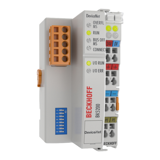
Page 8: Product Overview
Fig. 1: BK5200 – Bus Coupler for DeviceNet The BK5200 Bus Coupler connects the DeviceNet bus system to the modularly extendable electronic terminal blocks. One unit consists of one Bus Coupler, any number from 1 to 64 terminals and one bus end terminal. -
Page 9: Bk5250 - Introduction
Fig. 2: BK5250 – Compact Bus Coupler for DeviceNet The Compact Bus Coupler BK5250 for DeviceNet extends the Beckhoff Bus Terminal system by a cost- optimized version in a compact housing. Up to 64 Bus Terminals are supported; with the Terminal Bus Extension, up to 255 Bus Terminals can be connected. -
Page 10: Lc5200 - Introduction
Product overview LC5200 - Introduction Fig. 3: LC5200 - Low-cost Bus Coupler for DeviceNet The LC5200 low-cost bus coupler is characterized by its compact design and less expensive connection technology. It corresponds to the functions of the BK5210 DeviceNet Bus Coupler in relation to operation with Bus Terminals and its fieldbus properties. -
Page 11: Technical Data
CE, cULus, CE, cULus, ATEX [} 28] ATEX [} 28] ATEX [} 29] ATEX [} 28] System data DeviceNet BK5200, BK5210, BK5250, LC5200 Number of I/O modules Data transfer medium shielded, twisted copper wire with energy supply, 5-pin Max. cable length 500 m 250 m 100 m Data transfer rates 125 kbaud... -
Page 12: Basic Function Principles
Bus Couplers for all usual bus systems The Beckhoff Bus Terminal system unites the advantages of a bus system with the possibilities of the compact series terminal. Bus Terminals can be driven within all the usual bus systems, thus reducing the controller parts count. - Page 13 Basic Function Principles K-Bus The K-Bus is the data path within a terminal strip. The K-Bus is led through from the Bus Coupler through all the terminals via six contacts on the terminals' side walls. The end terminal terminates the K-Bus. The user does not have to learn anything about the function of the K-Bus or about the internal workings of the terminals and the Bus Coupler.
-
Page 14: Principle Of The Bus Terminal
Basic Function Principles Principle of the Bus Terminal Fig. 4: Principle of the Bus Terminal Version: 2.0.0 BK52x0 and LC5200... -
Page 15: Devicenet
The BECKHOFF DeviceNet devices have a powerful implementation of the protocol. Through active participation in the ODVA's technical committees, BECKHOFF are contributing to the further development of this bus system, and has in this way itself gathered profound DeviceNet expertise. -
Page 16: Data Exchange
Diagnostics The extensive diagnostic functions of the BECKHOFF DeviceNet devices allow rapid fault localisation. The diagnostic messages are transmitted over the bus and collated by the master. The status of the network connection, the device status, the status of the inputs and outputs and of the power supply are displayed by LEDs. -
Page 17: Fig. 7 Data Exchange
Basic Function Principles Analog outputs receive 16 bits of data, i.e. two bytes, per channel. An analog output terminal with 2 channels must therefore receive 4 bytes. A digital output terminal with 2 channels requires a total of 2 bits of data, 1 bit for each channel. First the data from all the analog outputs The first 4 bytes of an object transmitted to the terminal strip are assigned to the first analog output terminal, which is the analog output terminal closest to the Bus Coupler. -
Page 18: Vendor Id
0. As soon as an error occurs, the I/O ERR LED lights up and the status byte contains the value 1. 3.3.3 Vendor ID The Vendor ID is # 108 3.3.4 DeviceNet Group The BK5200, BK5210 and LC5200 Bus Couplers are exclusively Group 2 devices. Fig. 8: Overview of the identifiers used Version: 2.0.0 BK52x0 and LC5200... -
Page 19: Mounting And Wiring
Fig. 9: Spring contacts of the Beckhoff I/O components Dimensions The system of the Beckhoff Bus Terminals is characterized by low physical volume and high modularity. When planning a project it must be assumed that at least one Bus Coupler and a number of Bus Terminals will be used. -
Page 20: Installation On Mounting Rails
Mounting and wiring Fig. 10: Dimensions Installation on mounting rails WARNING Risk of injury through electric shock and damage to the device! Bring the Bus Terminals system into a safe, de-energized state before starting mounting, disassembly or wiring of the Bus Terminals. Mounting The Bus Couplers and Bus Terminals are attached to commercially available 35 mm mounting rails (DIN rail according to EN 60715) by applying slight pressure:... - Page 21 Mounting and wiring 1. Carefully pull the orange-colored lug approximately 1 cm out of the terminal to be disassembled, until it protrudes loosely. The lock with the mounting rail is now released for this terminal, and the terminal can be pulled from the mounting rail without excessive force. 2.
-
Page 22: Power Supply, Potential Groups
Mounting and wiring Power supply, potential groups Power supply The Bus Couplers require a 24 V DC supply for their operation. In the case of the BK52x0 Bus Couplers this is connected via the upper spring-loaded terminals marked "24 V" and "0 V". This supply voltage feeds not only the Bus Coupler electronics, but also the Bus Terminals via the K-bus. -
Page 23: Fig. 11 Bk5200, Bk5210, Bk5250 - Potential Groups
Note: All the Bus Terminals are electrically isolated from the K-bus. The K-bus is thus electrically isolated from everything else. Fig. 11: BK5200, BK5210, BK5250 – potential groups The LC5200 does not provide electrical isolation from the fieldbus and peripheral level. If the peripheral level nevertheless needs to have an electrically isolated implementation, this can easily be achieved through the use of isolating terminals (KL9xxx). -
Page 24: Electrical Isolation
Mounting and wiring Electrical isolation BK5200, BK5210 The BK5200 and BK5210 Bus Couplers have electrical isolation between the DeviceNet bus cable and the communication electronics of the Bus Coupler. Fig. 12: Potential levels of the BK5200 and BK5210 LC5200 The LC5200 does not provide electrical isolation from the fieldbus and peripheral level. If the peripheral level nevertheless needs to have an electrically isolated implementation, this can easily be achieved through the use of isolating terminals (KL9xxx). -
Page 25: Devicenet Connection - Pin Assignment
Mounting and wiring DeviceNet connection – pin assignment A 5-pin connector is supplied for the connection of the DeviceNet bus cable. When it is plugged into the Bus Coupler, pin 1 is at the top. The figure shows the socket in the Bus Coupler. The power supplied by this plug is isolated from the power supply of the terminal to the right of the Bus Coupler. -
Page 26: Bus Cable Lengths And Pin Assignment
Mounting and wiring Bus cable lengths and pin assignment The maximum length of cable which can be used depends on the selected baud rate. The following lengths should be understood as the total length of the main line plus any drop lines. Baud rate Bus length 500 kbit/s... -
Page 27: Fig. 17 Cable Assignment
Mounting and wiring Fig. 17: Cable assignment BK52x0 and LC5200 Version: 2.0.0... -
Page 28: Atex - Special Conditions (Standard Temperature Range)
80°C at the wire branching points, then cables must be selected whose tempera- ture data correspond to the actual measured temperature values! • Observe the permissible ambient temperature range of 0 to 55°C for the use of Beckhoff fieldbus compo- nents standard temperature range in potentially explosive areas! •... -
Page 29: Atex - Special Conditions (Extended Temperature Range)
80°C at the wire branching points, then cables must be selected whose tempera- ture data correspond to the actual measured temperature values! • Observe the permissible ambient temperature range of -25 to 60°C for the use of Beckhoff fieldbus com- ponents with extended temperature range (ET) in potentially explosive areas! •... -
Page 30: Continuative Documentation For Atex And Iecex
IECEx Pay also attention to the continuative documentation Ex. Protection for Terminal Systems Notes on the use of the Beckhoff terminal systems in hazardous areas according to ATEX and IECEx that is available for download on the Beckhoff homepage www.beckhoff.com! Version: 2.0.0... -
Page 31: Parameterization And Commissioning
Parameterization and Commissioning Parameterization and Commissioning Start-up behaviour of the Bus Coupler Immediately after being switched on, the Bus Coupler checks, in the course of a self-test, all the functions of its components and the communication on the K-bus/E-bus. The red I/O LED blinks while this is happening. After completion of the self-test, the Bus Coupler starts to test the attached Bus Terminals (the "Bus Terminal Test"), and reads in the configuration. -
Page 32: Fig. 19 Output Data In The Bus Coupler
Parameterization and Commissioning or input value is represented, according to the standard settings, by "7FFF" hex. Negative input/output values, e.g. -10 V are mapped as "1000" hex. The intermediate values are correspondingly proportional. A range with a resolution of 15 bits is not achieved for all input and output stages. With an actual resolution of 12 bits, the last 3 bits for outputs have no effect and for inputs they are read "0". -
Page 33: Fig. 20 Input Data In The Bus Coupler
Fig. 20: Input data in the Bus Coupler Process image in the BK5200 and in the PLC (scanner) Fig. 21: Process image in the BK5200 and in the PLC (scanner) Data consistency Data whose content is all correctly associated is said to be consistent. - Page 34 Parameterization and Commissioning instance, the consistency must be extended. The different bus systems guarantee consistency up to the required length. Correct transfer of the consistent data from the bus system master to the controller is important. The corresponding manual for the bus system will provide a detailed description of the correct procedure, in particular the description of the master interfaces used.
-
Page 35: Configuration Of The Bus Coupler
Set all the DIP switches to the desired configuration before you switch on the Bus Coupler. Switches 7 and 8 are used to set the baud rate, as shown in the following table. Fig. 22: BK5200 - Configuration Fig. 23: DIP switch... - Page 36 Parameterization and Commissioning Switch on the Bus Coupler When you have set all the DIP switches to the desired configuration you can switch on the Bus Coupler. Any changes you make to the switches while the system is in operation will have no effect until the next time it is switched on.
-
Page 37: Diagnostic Leds
Parameterization and Commissioning Diagnostic LEDs After switching on, the Bus Coupler immediately checks the connected configuration. Error-free start-up is indicated when the red "I/O ERR" LED goes out. If the "I/O ERR" LED blinks, an error in the area of the terminals is indicated. -
Page 38: Led Displays
Parameterization and Commissioning 5.4.1 LED displays Module Status MS Meaning green LED blinks Configuration is incorrect green LED is steadily lit Status is OK OVERFL red LED blinks K-bus error red LED is steadily lit Receive queue overflow Network Status NS Meaning CONNECT green LED blinks... -
Page 39: Led Function Matrix
NS tus NS tus NMS (LED red) (LED green) (duo LED) (duo LED) (duo LED) (duo LED) (duo LED) Products BK5200 BK5210B1 BK5210B2 BK5220 BK5250 LC5200 IP Compact IP Coupler LEDs green flash- Boot Up OK, IO Data length... - Page 40 NS tus NS tus NMS (LED red) (LED green) (duo LED) (duo LED) (duo LED) (duo LED) (duo LED) Products BK5200 BK5210B1 BK5210B2 BK5220 BK5250 LC5200 IP Compact IP Coupler LEDs red flashing Time-Out, no K-Bus error, Time-Out, no...
-
Page 41: Appendix
Appendix Appendix Composition of a process image in the Bus Coupler An example shows the assignment of input and output channels to the process image. The sample construction should consist of the following bus - terminal - assemblies: Position Functional groups on the rail POS01 Bus Coupler POS02... - Page 42 Appendix Area for bit-oriented data, digital outputs Relative byte address Bit position Process image in the controller Position in the block POS07 POS07 POS08 POS08 POS09 POS09 POS18 POS18 POS19 POS19 Area for byte-oriented data, analog inputs Relative byte address Bit position Process image in the controller Position in the block...
-
Page 43: Fig. 24 Process Image In The Bus Coupler - Output Data
Appendix Distribution of the process image in the Bus Coupler Fig. 24: Process image in the Bus Coupler – output data Fig. 25: Process image in the Bus Coupler – input data The base addresses I0 and O0 listed here are used as relative addresses or addresses in the Bus Coupler. Depending on the higher-level DeviceNet system, the addresses can appear at a freely selectable position in the process image of the controller by the bus master. -
Page 44: Support And Service
Please contact your Beckhoff branch office or representative for local support and service on Beckhoff products! The addresses of Beckhoff's branch offices and representatives round the world can be found on her internet pages: https://www.beckhoff.com You will also find further documentation for Beckhoff components there. - Page 45 Fig. 19 Output data in the Bus Coupler ....................Fig. 20 Input data in the Bus Coupler ...................... Fig. 21 Process image in the BK5200 and in the PLC (scanner) ............Fig. 22 BK5200 - Configuration ....................... Fig. 23 DIP switch............................
- Page 47 More Information: www.beckhoff.com/BKxxxx Beckhoff Automation GmbH & Co. KG Hülshorstweg 20 33415 Verl Germany Phone: +49 5246 9630 info@beckhoff.com www.beckhoff.com...
Need help?
Do you have a question about the BK5200 and is the answer not in the manual?
Questions and answers