
Related Manuals for Panametrics PanaFlow MV80


Summary of Contents for Panametrics PanaFlow MV80
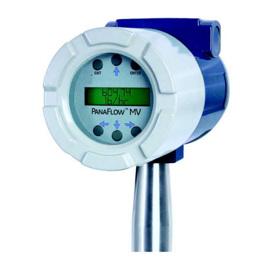
- Page 1 Flow PanaFlow™ MV80, MV82 & MV84 Vortex Volumetric and Mass Flow Meters User’s Manual 910-292 E panametrics.com May 2020...
- Page 3 User’s Manual 910-292 E April 2019 panametrics.com Copyright 2019 Baker Hughes company. This material contains one or more registered trademarks of Baker Hughes Company and its subsidiaries in one or more countries. All third-party product and company names are trademarks of their respective...
- Page 4 [no content intended for this page]...
- Page 5 Customer Notice for Oxygen Service Unless you have specifically ordered Panametrics optional O2 cleaning, this flow meter may not be fit for oxygen service. Some models can only be properly cleaned during the manufacturing process. Panametrics, is not liable for any damage or personal injury, whatsoever, resulting from the use of Panametrics standard mass flow meters for oxygen gas.
- Page 6 Repairs, Extended Warranties, Service Agreements and more. Please visit https://www.bakerhughesds.com/measurement-sensing/flow-measurement/flow-measurement-services for more details. Terms and Conditions Sales Terms and Conditions for your recent purchase of a Panametrics product, including the applicable product Warranty, can be found on our website. Typographical Conventions Note: These paragraphs provide information that provides a deeper understanding of the situation, but is not essential to the proper completion of the instructions.
- Page 7 Preface Local Safety Standards The user must make sure that he operates all auxiliary equipment in accordance with local codes, standards, regulations, or laws applicable to safety. Working Area WARNING! Auxiliary equipment may have both manual and automatic modes of operation. As equipment can move suddenly and without warning, do not enter the work cell of this equipment during automatic operation, and do not enter the work envelope of this equipment during manual operation.
- Page 8 The PanaFlow™ M80, M82, M84 and M84R fully complies with RoHS regulations (Directive 2011/65/EU). Waste Electrical and Electronic Equipment (WEEE) Directive Panametrics is an active participant in Europe’s Waste Electrical and Electronic Equipment (WEEE) take-back initiative (Directive 2012/19/EU). The equipment that you bought has required the extraction and use of natural resources for its production. It may contain hazardous substances that could impact health and the environment.
-
Page 9: Table Of Contents
Contents Chapter 1. Introduction Multi-Parameter Vortex Mass Flow Meters ............... . 1 1.1.1 Multi-Parameter Mass Flow Meters. - Page 10 Contents 2.6.1.2 DC Power Wiring ..................40 2.6.2 4-20 mA Output Connections .
- Page 11 Contents Chapter 4. Serial Communications HART Communications ..................97 4.1.1 Wiring .
- Page 12 Contents Returning Equipment to the Factory ................142 Appendix A.
-
Page 13: Chapter 1. Introduction
How the PanaFlow Vortex Mass Flow Meter Operates PanaFlow MV80, MV82, and MV84 Multi-Parameter Vortex Mass Flow Meters (see Figure 1 below) use a unique sensor head to monitor mass flow rate by directly measuring three variables-fluid velocity, temperature, and pressure. The built-in flow computer calculates the mass flow rate and volumetric flow rate based on these three direct measurements. -
Page 14: Velocity Measurement
Chapter 1. Introduction FLOW Figure 1: In-Line Vortex Multi-Parameter Mass Flow Meter Velocity Measurement The PanaFlow vortex velocity sensor is a patented mechanical design that minimizes the effects of pipeline vibration and pump noise, both of which are common error sources in flow measurement with vortex flow meters. The velocity measurement is based on the well-known Von Karman vortex shedding phenomenon. -
Page 15: Vortex Shedding Frequency
Chapter 1. Introduction 1.3.1 Vortex Shedding Frequency Von Karman vortices form downstream of a shedder bar into two distinct wakes. The vortices of one wake rotate clockwise while those of the other wake rotate counterclockwise. Vortices generate one at a time, alternating from the left side to the right side of the shedder bar. -
Page 16: Flow Velocity Range
Chapter 1. Introduction 1.3.3 Flow Velocity Range To ensure trouble-free operation, vortex flow meters must be correctly sized so that the flow velocity range through the meter lies within the measurable velocity range (with acceptable pressure drop) and the linear range. The measurable range is defined by the minimum and maximum velocity using Table 1 below. -
Page 17: Pressure Drop
Chapter 1. Introduction As shown in Figure 3 below, PanaFlow meters exhibit a constant Strouhal number across a large range of Reynolds numbers, indicating a consistent linear output over a wide range of flows and fluid types. Below this linear range, the intelligent electronics in PanaFlow automatically corrects for the variation in the Strouhal number with the Reynolds number. -
Page 18: Pressure Measurement
The output signal of insertion meters is the total flow rate in the channel. The accuracy of the total flow rate computation depends on adherence to the piping installation requirements given in Chapter 2. If adherence to those guidelines cannot be met, contact Panametrics for specific installation advice. 1.8.1... -
Page 19: Line Size, Process Connections And Materials
Chapter 1. Introduction 1.8.2 Line Size, Process Connections and Materials The MV80 and MV84 In-line model is built for line sizes ½ through 4 inch wafer or ½ through 12 inch flanged design using ANSI 150, 300, 600, PN16, 40, or 63 class flanges. JIS flanges available upon request. The MV82 Insertion model can be used in line sizes 2 inch and greater and is built with a compression fitting or packing gland design using 2 inch NPT, or 2 inch flanged connections (ANSI 150, 300, 600, PN16, 40, or 63 class flanges). - Page 20 Chapter 1. Introduction [no content intended for this page] PanaFlow™ MV80, MV82 & MV84 User’s Manual...
-
Page 21: Chapter 2. Installation
Chapter 2. Installation Chapter 2. Installation Installation Overview PanaFlow Vortex Flow Meter installations are simple and straightforward. Both the Series MV80 In-Line and Series MV82 Insertion type flow meter installations are covered in this chapter. After reviewing the installation requirements given below, see page 10 for Series MV80 installation instructions. -
Page 22: Unobstructed Flow Requirements
Chapter 2. Installation 2.1.2 Unobstructed Flow Requirements Select an installation site that will minimize possible distortion in the flow profile. Valves, elbows, control valves and other piping components may cause flow disturbances. Check your specific piping condition against the examples shown in Figure 4 below. -
Page 23: Recommended Meter Locations
Chapter 2. Installation 2.1.3 Recommended Meter Locations Figure 5: Liquid Horizontal Figure 6: Liquid Vertical PanaFlow™ MV80, MV82 & MV84 User’s Manual... - Page 24 Chapter 2. Installation Figure 7: Gas or Steam Horizontal Figure 8: Gas or Steam Vertical PanaFlow™ MV80, MV82 & MV84 User’s Manual...
-
Page 25: Series Mv80 In-Line Flow Meter Installation
ID of 1.939 in. (2 in. schedule 80). Do not install the meter in a pipe with an inside diameter smaller than the inside diameter of the meter. For schedule 160 and higher pipe, a special meter is required. Consult Panametrics before purchasing the meter. -
Page 26: Installing Wafer-Style Flow Meters
Chapter 2. Installation 2.2.2 Installing Wafer-Style Flow Meters Install the wafer-style meter between two conventional pipe flanges of the same nominal size as the flow meter (see Figure 10 below). If the process fluid is a liquid, make sure the meter is located where the pipe is always full. This may require locating the meter at a low point in the piping system. - Page 27 Chapter 2. Installation 2.2.2 Installing Wafer-Style Flow Meters (cont.) To install the meter, complete the following steps: Turn off the flow of process gas, liquid, or steam. Verify that the line is not pressurized. Confirm that the installation site meets the required minimum upstream and downstream pipe diameters. Insert the studs for the bottom side of the meter body between the pipe flanges.
-
Page 28: Installing Flange-Style Flow Meters
Chapter 2. Installation 2.2.3 Installing Flange-Style Flow Meters Install the flange-style meter between two conventional pipe flanges of the same nominal size as the flow meter (see Figure 11 below). If the process fluid is a liquid, make sure the meter is located where the pipe is always full. This may require locating the meter at a low point in the piping system. -
Page 29: Series Mv82 Insertion Flow Meter Installation
Chapter 2. Installation 2.2.3 Installing Flange-Style Flow Meters (cont.) To install the meter, complete the following steps: Turn off the flow of process gas, liquid, or steam. Verify that the line is not pressurized. Confirm that the installation site meets the required minimum upstream and downstream pipe diameters. Seat the meter level and square on the mating connections with the flange stamped with a flow arrow on the upstream side, with the arrow head pointing in the direction of flow. - Page 30 Chapter 2. Installation Confirm that the installation site meets the minimum upstream and downstream pipe diameter requirements. See Figure 4 on page 10. Use a cutting torch or sharp cutting tool to tap into the pipe. The pipe opening must be at least 1.875 inches in diameter (Do not attempt to insert the sensor probe through a smaller hole).
-
Page 31: Hot Tap Guidelines
Chapter 2. Installation 2.3.1.4 Hot Tap Guidelines WARNING! Hot tapping must be performed by a trained professional. US. regulations often require a hot tap permit. The manufacturer of the hot tap equipment and/or the contractor performing the hot tap is responsible for providing proof of such a permit. WARNING! All flow meter connections, isolation valves, and fittings for hot tapping must have the same pressure rating as the main pipeline or higher. - Page 32 Chapter 2. Installation 2.3.1.4 Hot Tap Guidelines (cont.) Proceed as follows: Confirm that the installation site meets the minimum upstream and downstream pipe diameter requirements. Weld a two inch mounting adapter on the pipe. Make sure the mounting adapter is within ± 5° perpendicular to the pipe centerline (see Figure 13 on page 18).
-
Page 33: Insertion Guidelines
Chapter 2. Installation 2.3.1.5 Insertion Guidelines The sensor head must be properly positioned in the pipe. For this reason, it is important that insertion length calculations are carefully followed. A sensor probe inserted at the wrong depth in the pipe will result in inaccurate readings. -
Page 34: Installing Flow Meters With A Compression Connection
Chapter 2. Installation 2.3.2 Installing Flow Meters with a Compression Connection Refer to Figure 15 below, and use the formula shown to determine insertion length for flow meters (NPT and flanged) with a compression process connection. Flow Flow Insertion Length Formula Where: I = S –... - Page 35 Chapter 2. Installation 2.3.2 Installing Flow Meters with a Compression Connection (cont.) Example: To install a Series MV82 meter with a standard probe (S = 29.47 inches) into a 14 inch schedule 40 pipe, the following measurements (in inches) are taken: •...
- Page 36 Chapter 2. Installation 2.3.2 Installing Flow Meters with a Compression Connection (cont.) CAUTION! The sensor alignment pointer must point downstream, in the direction of flow. WARNING! To avoid serious injury, DO NOT loosen the compression fitting under pressure. Refer to Figure 16 on page 23 and complete the following steps: Refer to Figure 15 on page 22 and calculate the required sensor probe insertion length for your system.
-
Page 37: Installing Flow Meters With A Packing Gland Connection
Chapter 2. Installation 2.3.3 Installing Flow Meters with a Packing Gland Connection Use the formula in Figure 17 below to determine the insertion depth for flow meters (NPT and flanged) equipped with an insertion tool. To install, see “Insertion Procedure for Flow Meters with Permanent Insertion Tool” on page 26 for instructions for meters with a permanent insertion tool. -
Page 38: Insertion Procedure For Flow Meters With Permanent Insertion Tool
Chapter 2. Installation 2.3.3 Installing Flow Meters with a Packing Gland Connection (cont.) Example 2 - NPT Style Meters: In this example, the length of thread engagement on the NPT style meters must also subtracted in the equation shown in Figure 17 on page 25. The length of the threaded portion of the NPT meter is 1.18 inches. Measure the threaded portion still visible after the installation and subtract that amount from 1.18 inches. - Page 39 Chapter 2. Installation 2.3.4 Insertion Procedure for Flow Meters with Permanent Insertion Tool (cont.) CAUTION! The sensor alignment pointer must point downstream, in the direction of flow. Note: If line pressure is above 500 psig, it could require up to 25 ft-lb of torque to insert the flow meter. Do not confuse this with possible interference in the pipe.
-
Page 40: Insertion Procedure For Flow Meters With Removable Insertion Tool
Chapter 2. Installation 2.3.5 Insertion Procedure for Flow Meters with Removable Insertion Tool Refer to Figure 19 below, and follow the instructions on the next page. Upper Retractor Bracket Depth Marker Arrow Stanchion Stem Lock Bolt (center) Scribe Mark Sensor Alignment Pointer Stem Stem Clamp Nuts... - Page 41 Chapter 2. Installation 2.3.5 Insertion Procedure for Flow Meters with Removable Insertion Tool (cont.) CAUTION! The sensor alignment pointer must point downstream, in the direction of flow. Note: If line pressure is above 500 psig, it could require up to 25 ft-lb of torque to insert the flow meter. Do not confuse this with possible interference in the pipe.
-
Page 42: Installing Flow Meters With A Packing Gland Connection (No Insertion Tool)
Chapter 2. Installation 2.3.6 Installing Flow Meters with a Packing Gland Connection (No Insertion Tool) Use the formula in Figure 20 below to determine the insertion depth for meters with a packing gland connection (NPT and flanged) without an insertion tool. Insertion Length Formula I = S –... -
Page 43: Adjusting The Meter Orientation
Chapter 2. Installation 2.3.6 Installing Flow Meters with a Packing Gland Connection (No Insertion Tool) (cont.) WARNING! The line pressure must be less than 50 psig for installation. To install the meter, complete the following steps: Calculate the required sensor probe insertion length. Fully retract the stem until the sensor head is touching the bottom of the stem housing. -
Page 44: Enclosure Adjustment (Series Mv80 Only)
Chapter 2. Installation Rotate display/keypad in 90° increments (maximum 180° from original position). Figure 21: Display/Keypad Viewing Adjustment CAUTION! The electronics boards are electrostatically sensitive. Wear a grounding wrist strap and make sure to observe proper handling precautions required for static-sensitive components. - Page 45 Chapter 2. Installation Loosen three setscrews and rotate enclosure (maximum 180° from original position) Figure 22: Enclosure Viewing Adjustment CAUTION! To avoid damage to the sensor wires, do not rotate the enclosure beyond 180° from the original position. Disconnect the power from the flow meter. Loosen the three set screws shown in Figure 22 above and rotate the display to the desired position.
-
Page 46: Loop Power Flow Meter Wiring Connections
Chapter 2. Installation Loop Power Flow Meter Wiring Connections WARNING! To avoid potential electric shock, follow National Electric Code safety practices or your local code when wiring this unit to a power source and to peripheral devices. Failure to do so could result in injury or death. All wiring procedures must be per-formed with the power off. -
Page 47: Ma Output Connections
Chapter 2. Installation Connect 4-20 mA loop power (12 to 36 VDC at 25 mA, 1W max.) to the +PWR and -PWR terminals on the terminal block (see Figure 24 below). Torque all connections to 4.43 to 5.31 in-lbs (0.5 to 0.6 Nm). The DC power wire size must be 20 to 12 AWG with 1/4 inch (7 mm) of insulation stripped from each conductor. - Page 48 Chapter 2. Installation The pulse output requires a separate 5 to 36 VDC power supply (see Figure 26 or Figure 27 below). The pulse output optical relay is a normally-open single-pole relay. The relay can conduct a current up to 40 mA. It is isolated from the meter electronics and power supply.
-
Page 49: Frequency Output Connections
Chapter 2. Installation 2.5.4 Frequency Output Connections The frequency output is used for a remote counter. It can be scaled to output a 1 to 10 kHz signal proportional to mass or volume flow, temperature, pressure or density. The frequency output requires a separate 5 to 36 VDC power supply (see Figure 28 or Figure 29 below). The frequency output optical relay is a normally-open single-pole relay. -
Page 50: Remote Electronics Wiring
Chapter 2. Installation 2.5.6 Remote Electronics Wiring The remote electronics enclosure should be mounted in a convenient, easy-to-reach location. For hazardous location installations, make sure to observe agency requirements for installation. Allow some slack in the interface cable between the junction box and the remote electronics enclosure. To prevent damage to the wiring connections, do not put stress on the wiring connections at any time. -
Page 51: Line Power Meter Wiring Connections
Chapter 2. Installation Line Power Meter Wiring Connections WARNING! To avoid potential electric shock, follow National Electric Code safety practices or your local code when wiring this unit to a power source and to peripheral devices. Failure to do so could result in injury or death. All AC power connections must be in accordance with published CE directives. -
Page 52: Input Power Connections
Chapter 2. Installation 2.6.1 Input Power Connections To access the wiring terminal blocks, locate and loosen the small set screw which locks the small enclosure cover in place. Unscrew the cover to expose the terminal block. 2.6.1.1 AC Power Wiring CAUTION! The AC wire insulation temperature rating must meet or exceed 90°C (194°F), maximum operating voltage 600VRMS. -
Page 53: Ma Output Connections
Chapter 2. Installation 18 to 36 VDC @300 mA Max. + Pwr DC Power – Pwr DC Common Figure 34: DC Power Connections 2.6.2 4-20 mA Output Connections The standard PanaFlow meter has a single 4-20 mA loop. Two additional loops are available on the optional communication board. -
Page 54: Frequency Output Connections
Chapter 2. Installation 2.6.2 4-20 mA Output Connections (cont.) The maximum loop resistance (load) for the current loop output is dependent upon the supply voltage and is given in Figure 38 below. The 4-20 mA loop is optically isolated from the flow meter electronics. is the total resistance in the loop, including the wiring resistance. - Page 55 Chapter 2. Installation 2.6.3 Frequency Output Connections (cont.) R current limit Freq Out + Freq. Out voltage = +V Select resistor so that current Freq Out – through Freq. Out < 40mA Figure 39: Isolated Frequency Output Using External Power Supply R current limit ~10K DC Power + Pwr...
-
Page 56: Pulse Output Connections
Chapter 2. Installation 2.6.4 Pulse Output Connections The pulse output is used for a remote counter. When the preset volume or mass, as defined in the totalizer settings (see “The Totalizer #1 Menu” on page 83) has passed through the meter, the output provides a 50 millisecond square pulse. -
Page 57: Alarm Output Connections
Chapter 2. Installation 2.6.5 Alarm Output Connections One alarm output (Alarm 1) is included on the standard PanaFlow meter. Two or more alarms (Alarm 2 and Alarm 3) are included on the optional communication board. The alarm output is used for transmitting high or low process conditions, as defined in the alarm settings (see “The Alarms Menu”... -
Page 58: Remote Electronics Wiring
Chapter 2. Installation 2.6.6 Remote Electronics Wiring The remote electronics enclosure should be mounted in a convenient, easy to reach location. For hazardous location installations, make sure to observe agency requirements for installation. Allow some slack in the interface cable between the junction box and the remote electronics enclosure. -
Page 59: Optional Input Wiring
Chapter 2. Installation 2.6.7 Optional Input Wiring The meter has two optional input wiring terminals, maximum wire size is 16 AWG. These can be used to input a Remote or Second RTD input in situations such as: an Energy Monitoring meter, the input of a Remote Pressure Transducer, to pass a Contact Closure, for a Remote Density measurement, etc. -
Page 60: Optional External 4-20 Ma Input Wiring
Chapter 2. Installation 2.6.7.2 Optional External 4-20 mA Input Wiring The meter is set to have Option 1 used for the external input. Programming menus that pertain to the optional 4-20 mA input are located in “Hidden Diagnostics Menus” on page 129. Refer to Figure 51 below to wire the external 4-20 mA input into the flow meter using an external power supply. -
Page 61: Optional External 4-20 Ma Input And Rtd Wiring
Chapter 2. Installation 2.6.7.2 Optional External 4-20 mA Input Wiring (cont.) Refer to Figure 53 below to wire the external 4-20 mA input into the flow meter using power from the 24 VDC output of an AC powered meter. Option 1 Option 2 AC units only. -
Page 62: Optional Energy Ems External 4-20 Ma Input And Rtd Wiring
Chapter 2. Installation Figure 55: External 4-20 mA Input and RTD Wiring - High Power 2.6.7.4 Optional Energy EMS External 4-20 mA Input and RTD Wiring Figure 56: Energy EMS External 4-20 mA Input and RTD Wiring - High Power 2.6.7.5 Optional Contact Closure Input Wiring Refer to Figure 57 below to wire an external switch input into the flow meter. -
Page 63: Meter Initial Setup
Chapter 2. Installation Meter Initial Setup 2.7.1 Power Over Ethernet (POE) Wiring Connections The NEMA 4X enclosure contains an integral wiring compartment with one dual strip terminal block (located in the smaller end of the enclosure). Two 3/4-inch female NPT conduit entries are available for separate power and signal wiring. -
Page 64: Poe Power Wiring
Chapter 2. Installation Figure 59: DC Power Connections 2.7.3 POE Power Wiring CAUTION! The DC wire insulation temperature rating must meet or exceed 85°C (185°F), maximum operating voltage 300 VRMS. Alternatively POE injector may be used for example: TRENDnet TPE-115Gi. Connect the unit with the Ethernet cable to POE enable Ethernet switch (POE option does not require a separate power supply). -
Page 65: Ip Setup Network Configuration Tool
Chapter 2. Installation • Static IP address • Dynamically assigned IP address via DHCP (Dynamic Host Configuration Protocol). For static configuration consult your network administrator which IP address to use. 2.7.5.1 IP Setup Network Configuration Tool: IPSetup is used to configure network settings on your Vortex/TCP device such as IP Address, Mask, Gateway, DNS Server. -
Page 66: Ipsetup Faq
Chapter 2. Installation • If you are trying to talk to a device on the other side of a router. Check to see if the PC and Vortex/TCP devices are on the same LAN. 2.7.7 IPSetup FAQ • If DHCP serve can't assign an address to the meter, it will switch to AutoIP. AutoIPs are special addresses in the range 169.254.XXX.XXX. -
Page 67: Web Page
Chapter 2. Installation 2.7.8.1 WEB page Figure 63: Main/home page Above is a Figure of the main page of the webpage with the menu selections on the left side. When the meter is initially powered up, it scans for connected meters. This version is intended for master/slave configuration with multiple meters connected to a single gateway. - Page 68 Chapter 2. Installation Figure 65: Meter The above Figure display what values are available in the Meter Menu. Figure 66: Fluid The above Figure displays the values of the Fluid Menu. PanaFlow™ MV80, MV82 & MV84 User’s Manual...
- Page 69 Chapter 2. Installation Figure 67: Diagnostics The above Figure shows the values of the Diagnostics Menu. Figure 68: Configuration The above Figure shows the Configuration page options. Figure 69: Data log Figure 70: Startup log PanaFlow™ MV80, MV82 & MV84 User’s Manual...
-
Page 70: Web Configuration Interface
Chapter 2. Installation 2.7.9 WEB Configuration Interface Clicking on CONFIGURE Menu link opens the following page. Figure 71: Configuration Connection to the Configuration interface is done using encrypted protocol HTTPS. When connected for the first time, your browser and the unit need to perform a verification. This process is slightly different in different browsers. For the initial set up of the webpage please click the link “Click here if you are on the local network”. - Page 71 Chapter 2. Installation Figure 73: Fire Fox Add Exception Note: If you selected the link “Click here if you are on the local network and reopen in this frame”, the browser will not have the “Add Exception” button. We recommend using the first link when connecting to the new unit for the first time.
- Page 72 Chapter 2. Installation On Windows IE Explorer, the browser will show page as shown below. You need to click the link “Continue to this website (not recommended)”. In some versions of IE it may not show this link. In such case upgrade IE to version 11 or better user different browser, e.g. Firefox. Internet Explorer HTTPS warning page.
-
Page 73: 2.7.10 Internet Connection To The Meter, Security Issues
Chapter 2. Installation Figure 78: Configuration Interface In Frame 2.7.10 Internet connection to the meter, security issues Typically the meter is connected to the Local Area Network (LAN) with non-routable Private Network Address (192.168.xx.xx, 10.xx.xx.xx, 172.16-31.xx.xx). Th ere are two options to setup the meter from the Internet: •... -
Page 74: Modbus/Tcp Interface
Chapter 2. Installation Corporate gateways can have additional security enhancing measures, like sourcing. Sourcing addresses only allow access from certain individual IPs or networks. If security concerns are an issue, you may limit access to the meter using encrypted protocol only: port 443, https. On special request VortexInst can add special capability of Access Control List (ACL) to insecure by definition Modbus protocol. -
Page 75: Mbgui.exe Simple Modbus/Tcp Client
Chapter 2. Installation Figure 79: EXE Folder 2.7.11.2 MBGUI.EXE Simple Modbus/TCP client Figure 80: MBGUI.EXE Interface This is a simple Modbus/TCP client configured for use with VRTX/TCP meter. The names and location of registers are stored in mbgui.ini file. This file is created at start up and contains default definitions. The structure of the application uses the following approach accepted for VorTex 's meters supporting Modbus/RTU. -
Page 76: Console Modbus/Tcp Client Mbus.exe
Chapter 2. Installation Group” selector will show it in right panel. You can rename the application to something more meaningful for you (please avoid spaces in program name). In this case it will rename accordingly the INI file. By this you may create several clients for different meters. -
Page 77: 2.7.12 Data Logging
Chapter 2. Installation Figure 83: MBUS.exe Hex example 2.7.12 Data Logging VRTX/TCP meter has internal logging capability. The data is logged to micro SD card inside unit. The capacity of SD card may vary from 4 to 32 GB. The size of card and free space are shown on StartUp Log page. Card is formatted as FAT32 with long file name disabled. - Page 78 Chapter 2. Installation ..05 - May 160501.CSV 160502.CSV - Daily files in Comma Separated Variables text format. Figure 85: Log Files To download file to your PC right click on it and select “save”. You may also open it immediately. It will be opened as text file or in EXCEL depending on your settings of used browser.
- Page 79 Chapter 2. Installation In this example it is offering to open the file in LibreOffice Calc - analog of Windows EXCEL. It then asks about details of CSV format: what to use as field separators. Select "comma". Click OK and it will open the file in EXCEL (CALC). Figure 87: Text Import file PanaFlow™...
- Page 80 Chapter 2. Installation First three columns in table A, B, and C are fixed and always present. All other are configurable on SD Log Config page on CONFIGURE form. The names of columns are self-explanatory. Column C (Secs) shows number of seconds since meter was restarted. Columns named PU, TU, VFU display Pressure, Temperature, Volume Flow Units accordingly.
-
Page 81: Dummy Registers Group 9000
Chapter 2. Installation The SD Log Config page is the following. Just select desired items and click SET button at the bottom of the form. Figure 89: SD Card Configuration Page 2.7.12.1 Dummy registers group 9000 Client can read and write into Dummy Modbus registers 9000 to 9999. These registers may used for storing some process variables and logged synchronously with other VRTX Meter data. -
Page 82: Other Methods Of Retrieving Log Files
Chapter 2. Installation Figure 90: MB9K Config example Example of Dummy registers log. Figure 91: Dummy register log example 2.7.12.2 Other methods of retrieving log files WGET: Retrieving log files could be automated using Internet-standard utility WGET. This utility readily available on Linux machines and for Windows can downloaded from here: https://www.gnu.org/software/wget/ or install Linux simulator on Windows WinBash, which also contains WGET: http://win-bash.sourceforge.net/ To read daily file for specific date use the following WGET command:... - Page 83 Chapter 2. Installation WGET http://10.10.10.79/LOGS/2016/05/160527.CSV (where first 2 digits - year, next - month, next day). This instruction will download daily log file for date: 05/27/2016. FTP: VRTX/TCP meter has capability of accessing the file system on SD card via FTP protocol. For that you may use any specialized FTP client or even File browser on Linux or Windows systems.
-
Page 84: 2.7.13 Update Of Firmware
Chapter 2. Installation 2.7.13 Update of Firmware VORTEX meter firmware can be updated on-line. For that there are two applications: • AutoUpdate Standard update utility using UDP protocol. Local network only. • TcpUpdate Update utility using TCP protocol allowing access from other networks. In revision 1.0 of VORTEX/TCP TcpUpdate is disabled. -
Page 85: Chapter 3. Operating Instructions
The following steps should be taken to minimize the likelihood of a pressure surge damaging the PanaFlow MV80/82 vortex flow meter: The vortex flow meter must be located a minimum of 10 pipe diameters downstream from the pressure release valve, but 15 pipe diameters is recommended whenever possible. - Page 86 Chapter 3. Operating Instructions Flow Meter Display/Keypad (cont.) ENTER EXIT PanaFlow™ MV Figure 94: Magnetic Keypad Operation Figure 95 below shows a picture of the display/keypad. From Run Mode, the ENTER key enables access to the Setup Menus through a password screen. Within the Setup Menus, pressing ENTER activates the current field. To set new ...
-
Page 87: Display Contrast Adjustment
Chapter 3. Operating Instructions Display Contrast Adjustment The flow meter display contrast is set at the factory but if the dis-play characters appear too dark or too light proceed as follows: Hold down the “Exit” button on the front panel for 5 to 10 seconds. “Setting Contrast” will appear. Push the “Up”... - Page 88 Chapter 3. Operating Instructions Run Mode Screens ENTER Mass Flow Password Rate Volume ENTER Flow Rate Setup Press EXIT to Menus return to Run Mode Pressure Energy EMS Energy Meters Only Density keys to access Total each item Alarm 1 Status Alarm 2 Status...
-
Page 89: Using The Setup Menus
Chapter 3. Operating Instructions Using the Setup Menus 3.5.1 A Menu Map Figure 97: Complete Map of Setup Menus PanaFlow™ MV80, MV82 & MV84 User’s Manual... -
Page 90: Programming The Flow Meter
Chapter 3. Operating Instructions 3.5.2 Programming the Flow Meter Enter the Setup Menu by pressing the ENTER key until prompted for a password. Note: All outputs are disabled while using the Setup Menus. Use the keys to select the new password characters (1234 is the factory-set password). When the password is correctly displayed, press ENTER to continue. -
Page 91: Example For Calculating Output Current
Chapter 3. Operating Instructions 3.5.3 The Output Menu (cont.) Figure 98: Output Menu Map 3.5.4 Example for Calculating Output Current Assume Output 1 is scaled as above for mass flow with 4 mA = 0 lb/hr and 20 mA = 100 lb/hr. Output 1 current = ((Flow rate / 100) x 16 mA) + 4 mA. -
Page 92: The Display Menu
Chapter 3. Operating Instructions 3.5.5 The Display Menu Use the Display Menu shown in Figure 99 below to set the cycle time for automatic screen sequencing used in Run Mode, change the precision of displayed values, smooth the values or enable or disable each item displayed in the Run Mode screens. - Page 93 Chapter 3. Operating Instructions pressing the keys until Alarm [1] appears. The lower line displays the mass flow rate at which the alarm activates. Note: All outputs are disabled while using the Setup Menus. First, set the desired units of measurement: keys to move to the Units Menu (see “The Units Menu”...
- Page 94 Chapter 3. Operating Instructions 3.5.6 The Alarms Menu (cont.) ENTER Run Mode Password ENTER Alarms *see below Menu keys to access menus <Measure> None Mass < Mode > Relay Alarm 1 <Measure> units Volume None More > xxxx **Energy HIGH Alarm (>) LOW Alarm (<) Temp 1,2 Press...
-
Page 95: The Totalizer #1 Menu
Chapter 3. Operating Instructions 3.5.7 The Totalizer #1 Menu Use the Totalizer Menu to configure and monitor the totalizer. The totalizer maximum count is 999,999,999 at which point it will roll over to 0. The totalizer output is a 50 millisecond (.05 second) positive pulse (relay closed for 50 milliseconds). - Page 96 Chapter 3. Operating Instructions 3.5.7 The Totalizer #1 Menu (cont.) ENTER Run Mode Password ENTER Totalizer Menu keys to access menus Totaling Inactive Mass Example: Volume Energy Maximum flow rate = 600 gallons per minute (600 gallons per minute = 10 gallons per second). If unit per pulse is set to 600 gallons per pulse, (unit)/Pulse the totalizer will pulse once every minute.
-
Page 97: The Totalizer #2 Menu
Chapter 3. Operating Instructions 3.5.8 The Totalizer #2 Menu Refer to Figure 102 below, and use Totalizer #2 to Monitor Flow or Energy. The totalizer maximum count is 999,999,999 at which point it will roll over to 0. Note: Totalizer #2 does not operate a relay - it is for monitoring only. ENTER Run Mode Password... -
Page 98: The Energy Menu For Ems Energy Meters Only
Chapter 3. Operating Instructions 3.5.9 The Energy Menu for EMS Energy Meters Only There are several possibilities regarding the measurement of water or steam energy, given the location of the meter and the use of a second RTD. Table 3 below summarizes the possibilities: Table 3: Configuration Options Fluid Meter Location... - Page 99 Chapter 3. Operating Instructions 3.5.9 The Energy Menu for EMS Energy Meters Only (cont.) ENTER Run Mode Password ENTER Energy Menu keys to access menus Loc in Sent Flow Yes or No Heating System Yes or No % Returned Figure 103: The Energy Menu for EMS Energy Meters Only PanaFlow™...
-
Page 100: 3.5.10 The Fluid Menu
Chapter 3. Operating Instructions 3.5.10 The Fluid Menu Use the Fluid Menu (see Figure 104 on page 89) to configure the flow meter for use with common gases, liquids and steam. Your flow meter is pre-programmed at the factory for your application's process fluid. Reference Richard W. - Page 101 Chapter 3. Operating Instructions 3.5.10 The Fluid Menu (cont.) Figure 104: The Fluid Menu PanaFlow™ MV80, MV82 & MV84 User’s Manual...
-
Page 102: The Units Menu
Chapter 3. Operating Instructions 3.5.11 The Units Menu Use the Units Menu (see Figure 105 below) to configure the flow meter with the desired units of measurement. These are global settings and determine what appears on all screens. ENTER Run Mode Password ENTER Units... -
Page 103: 3.5.12 The Time & Date Menu
Chapter 3. Operating Instructions 3.5.12 The Time & Date Menu Use the Time and Date Menu (see Figure 106 below) to enter the correct time and date into the flow meter's memory. The parameters are used in the Run Mode and the alarm and system log files. Note: Time is displayed in AM/PM format, but military format is used to set the time. -
Page 104: 3.5.13 The Diagnostics Menu
Chapter 3. Operating Instructions 3.5.13 The Diagnostics Menu Use the Diagnostics Menu (see Figure 107 on page 93) to simulate operation and review the system files. The system log files contain time/date stamped messages including: power on, power off, programmed time outs, parameter faults, incorrect password entry and other various information relative to system operation and programming. - Page 105 Chapter 3. Operating Instructions 3.5.13 The Diagnostics Menu (cont.) ENTER Run Mode Password ENTER Diagnostics Menu keys to access menus Simulate Vortex Sim Vor Freq Frequency (Hz) *Simulate Temperature Sim Temp 1,2 For a V model in any fluid, enter nominal operating temperature and pressure as simulated values in the diagnostics menu.
-
Page 106: 3.5.14 The Calibration Menu
The Vortex Coef Ck and Low Flow Cutoff are set at the factory. Consult Panametrics for help with these settings if the meter is showing erratic flow rate readings. Figure 108: The Calibration Menu... -
Page 107: 3.5.15 The Password Menu
Chapter 3. Operating Instructions 3.5.15 The Password Menu Use the Password Menu (see Figure 109 below) to set or change the system password. The factory-set password is 1234. ENTER Run Mode Password ENTER Password Menu keys to access menus Set Password 1234 Figure 109: The Password Menu PanaFlow™... - Page 108 Chapter 3. Operating Instructions [no content intended for this page] PanaFlow™ MV80, MV82 & MV84 User’s Manual...
-
Page 109: Chapter 4. Serial Communications
Chapter 4. Serial Communications Chapter 4. Serial Communications HART Communications The HART Communications Protocol (Highway Addressable Remote Transducer Protocol) is a bidirectional digital serial communications protocol. The HART signal is based on the Bell 202 standard and is superimposed on the 4-20 mA Output 1. -
Page 110: Hart Dc Powered Meter Wiring
Chapter 4. Serial Communications 4.1.1.2 HART DC Powered Meter Wiring Vortex Meter R load, Current Power 250 ohm Meter Supply minimum Field Connection Remote Connection for Communicator for Communicator Figure 111: HART DC Powered Meter Wiring PanaFlow™ MV80, MV82 & MV84 User’s Manual... -
Page 111: Hart Ac Powered Meter Wiring
Chapter 4. Serial Communications 4.1.1.3 HART AC Powered Meter Wiring Vortex Meter R load, Current 250 ohm Meter minimum Field Connection Remote Connection for Communicator for Communicator Figure 112: HART AC Powered Meter Wiring PanaFlow™ MV80, MV82 & MV84 User’s Manual... -
Page 112: Hart Commands With The Digital Display Menu
Chapter 4. Serial Communications 4.1.2 HART Commands with the Digital Display Menu Figure 113: HART Commands with the Online Menu PanaFlow™ MV80, MV82 & MV84 User’s Manual... - Page 113 Chapter 4. Serial Communications 4.1.2 HART Commands with the Digital Display Menu (cont.) Figure 114: HART Commands with the Analog Output Menu PanaFlow™ MV80, MV82 & MV84 User’s Manual...
- Page 114 Chapter 4. Serial Communications 4.1.2 HART Commands with the Digital Display Menu (cont.) Figure 115: HART Commands with the Fluid Menu PanaFlow™ MV80, MV82 & MV84 User’s Manual...
- Page 115 Chapter 4. Serial Communications 4.1.2 HART Commands with the Digital Display Menu (cont.) Diagnostics Menu 1 Vel 1 Vtx Freq From Online Menu 2 Pres 2 Sim Vtx Freq 3 Temp 3 Vtx AtoD 4 Temp 2 4 Filter Set 5 Internal Temp 5 Change Filter Set 6 Vortex Diag.
- Page 116 Chapter 4. Serial Communications 4.1.2 HART Commands with the Digital Display Menu (cont.) Sensor Cal Menu 1 K Factor 2 Base Reynolds * 1 Calibration Review From Online Menu 2 Ck Value 1 Vol unit 1 Vtx Freq 2 Vortex Sensor 3 Low flow cutoff 2 USL 2 Sim Vtx Fr eq...
-
Page 117: Hart Commands With The Generic Digital Display Menu
Chapter 4. Serial Communications 4.1.3 HART Commands with the Generic Digital Display Menu Note: Use password 16363. Online Menu From Device setup / Review 1 Device setup 1 Pr ocess Variables 1 PV 1 Model 1 4 mA 2 PV 2 PV % Rnge 2 Distributor 2 20 mA... -
Page 118: Modbus Communications
Chapter 4. Serial Communications Modbus Communications WARNING! Place the controls in manual mode when making configuration changes to the vortex meter. 4.2.1 Applicable Flow Meter Models PanaFlow Mass Flow Meters, Models MV80 and MV82 with Modbus communication protocol and firmware version 4.00.58 and above are capable of Modbus commuinications. -
Page 119: Wiring
Chapter 4. Serial Communications 4.2.4 Wiring An RS485 daisy chained network configuration, as shown in Figure 119 below, is recommended. Do not use a star, ring, or cluster arrangement. RS-485 Master RS-485 – RS-485 + RS-485 GND Other Device 1 Vortex Meter Other Device 2, etc. -
Page 120: Menu Items
Chapter 4. Serial Communications 4.2.6 Menu Items The following menu items are in the Output Menu and allow selection and control of the Modbus communication protocol. 4.2.6.1 Address When the Modbus protocol is selected, the Modbus address is equal to the user programmable device address if it is in the range 1…247, in accordance with the Modbus specification. -
Page 121: Modbus Protocol
Chapter 4. Serial Communications 4.2.6.5 Modbus Protocol The Modbus RTU protocol is supported in this implementation. Supported baud rates are 1200, 2400, 4800, 9600, 19200, 38400, 57600, and 115200. The default baud rate is 19200 baud. Depending upon the Modbus protocol selected, data is transmitted in 8-bit data frames with even or odd parity and 1 stop bit, or no parity and 2 or 1 (non-standard) stop bits. -
Page 122: Register Definitions
Chapter 4. Serial Communications 4.2.6.6 Register Definitions The meter serial number and those variables that are commonly monitored (mass, volume and energy flow rates, total, pressure, temperature, density, viscosity, Reynolds number, and diagnostic variables such as frequency, velocity, gain, amplitude and filter setting) are accessible via the Modbus protocol. Long integer and floating point numbers are accessed as pairs of 16-bit registers in the register order selected in the Modbus Order menu. - Page 123 Chapter 4. Serial Communications 4.2.6.6 Register Definitions (cont.) Table 8 below shows the registers that are available with the energy meter firmware. Table 8: Energy Firmware Registers Registers Variable Data Type Units Function Code Addresses 30527-30528 Totalizer #2 unsigned long display units* 03, 04 526-527...
-
Page 124: Exception Status Definitions
Chapter 4. Serial Communications 4.2.6.7 Exception Status Definitions The Read Exception Status command (function code 07) returns the exception status byte, which is defined as shown in Table 10 below. This byte may be cleared by setting “coil” register #00003 (function code 5, address 2, data = 0xff00). -
Page 125: Error Responses
Chapter 4. Serial Communications 4.2.6.10 Error Responses If an error is detected in the message received by the unit, the function code in the response is the received function code with the most significant bit set, and the data field will contain the exception code byte (see Table 12 below). Table 12: Exception Codes Exception Code Description... -
Page 126: Examples
Chapter 4. Serial Communications 4.2.6.14 Examples Read the exception status byte from the device with address 1: 01 07 41 E2 01 Device address 07 Function code 04 = read exception status A typical response from the device is as follows: 01 07 03 62 31 01 Device address... - Page 127 Chapter 4. Serial Communications 4.2.6.14 Examples (cont.) An attempt to read register(s) that don't exist: 01 04 00 00 00 50 F1 D2 01 Device address 04 Function code 4 = read input register 00 00 Starting address 00 50 Number of registers = 80 F0 36 CRC This results in an error response as follows: 01 84 02 C2 C1...
-
Page 128: Bacnet Ms/Tp Communications
Chapter 4. Serial Communications BACnet MS/TP Communications 4.3.1 BACnet MS/TP Description The BACnet Master-Slave/Token-Passing (MSTP) driver implements a data link protocol that uses the services of the RS-485 physical layer. The MS/TP bus is based on BACnet standard protocol SSPC-135, Clause 9. BACnet MS/TP protocol is a peer-to-peer, multiple master protocols based on token passing. -
Page 129: Supported Bacnet Objects
Chapter 4. Serial Communications 4.3.4 Supported BACnet Objects A BACnet object represents physical or virtual equipment information, as a digital input or parameters. The MV 80 and MV 82 Vortex Mass Flow Meters present the following object types: Device Object Analog Input Binary Input Binary Value... - Page 130 Chapter 4. Serial Communications Table 16: Properties Object Types Object Types Properties Device Analog Input Binary Input Binary Value Reliability Out_Of_Service (W) (W) (W) Units Polarity (W) Priority_Array Relinquish_Default Status_Flag Present_Value (W) ...
-
Page 131: Device Object
The Device object default property values are listed in Table 17 below. Table 17: Properties Default Values Properties Default Values object-identifier object-name Device,1 object-type Device system-status operational vendor-name Panametrics Measurement & Control vendor-identifier model-name Multivariable Flow Meter firmware-revision application-software-version 1.07 protocol-version protocol-revision protocol-services-supported {F,F,F,F,F,F,F,F,F,F,F,F,T,F,T,T,T,T,F,F,F,F,F,F,F,F,F,F,F,F,T,T,F,F,F,F,F} protocol-object-types-supported... -
Page 132: Analog Input Object
Chapter 4. Serial Communications 4.3.4.2 Analog Input Object MV 80 and MV 82 Vortex Mass Flow Meters Analog Input type objects are described in table below. Object Instance Object Name Unit Description Volume Flow cubic-feet-per-second, This AI object is used to measure volume flow. cubic-feet-per-minute, us-gallons-per-minute, imperial-gallons-per-minute,... - Page 133 Chapter 4. Serial Communications Object Instance Object Name Unit Description Energy Flow Kilowatts, Horsepower, btus-per-hour, kilo-btus-per-hour, megawatts Totalizer 1 and If Totalizer selection for Mass An electronic counter which records the total Totalizer 2 measure – accumulated flow over a certain range of time. pounds-mass-per-second, grams-per-second, kilograms-per-second,...
-
Page 134: Binary Input Objects
Chapter 4. Serial Communications Object Instance Object Name Unit Description Scaled Freq hertz Flow Velocity feet-per-second Viscosity centipoises Frequency hertz VorTex Amp millivolts FilterSetting hertz 4.3.4.3 Binary Input Objects The MV 80 and MV82 Vortex Mass Flow Meters Binary Input type objects are described in Table 18 below. Table 18: Binary Input Object Types Object Object... -
Page 135: Annex - Bacnet Protocol Implementation Conformance Statement
Chapter 4. Serial Communications 4.3.5 ANNEX - BACnet Protocol Implementation Conformance Statement Date: 19-April-2012 Vendor Name: VorTex Instruments Product Name: Pro-V M22 multivariable flow-meter Product Model Number: M22/M23 VT/VTP Applications Software Version: 1.07 Firmware Revision: N/A BACnet Protocol Revision: 4 Product Description: VorTex multivariable flow-meter BACnet Standardized Device Profile (Annex L): ... - Page 136 Chapter 4. Serial Communications 4.3.5 ANNEX - BACnet Protocol Implementation Conformance Statement (cont.) Table 21: Services Supported Read Property Execute Write Property Execute Read Property Multiple Execute Write Property Multiple Execute Who-Is Execute I-Am Initiate Who-Has Execute I-Have Initiate Device Communication Control Execute Segmentation Capability: ...
- Page 137 Chapter 4. Serial Communications 4.3.5 ANNEX - BACnet Protocol Implementation Conformance Statement (cont.) Object List: Table 24: Properties of Analog Input/Value Object Types Name Present Value Status Flags Event State Out of Service Units Volume Flow F,F,F,F Normal False Mass Flow F,F,F,F Normal False...
- Page 138 Chapter 4. Serial Communications 4.3.5 ANNEX - BACnet Protocol Implementation Conformance Statement (cont.) Data Link Layer Options: BACnet IP, (Annex J) BACnet IP, (Annex J), Foreign Device ISO 8802-3, Ethernet (Clause 7) ANSI/ATA 878.1, 2.5 Mb. ARCNET (Clause 8) ANSI/ATA 878.1, EIA-485 ARCNET (Clause 8), baud rate(s) MS/TP master (Clause 9), baud rate(s): 9600, 19200, 38400 MS/TP slave (Clause 9), baud rate(s): Point-To-Point, EIA 232 (Clause 10), baud rate(s):...
-
Page 139: Acronyms And Definitions
Chapter 4. Serial Communications 4.3.5 ANNEX - BACnet Protocol Implementation Conformance Statement (cont.) Character Sets Supported: Indicating support for multiple character sets does not imply that they can all be supported simultaneously. ANSI X3.4 IBM™/Microsoft™DBCS ISO 8859-1 ISO 10646 (UCS-2) ISO 10646 (UCS-4) JIS C 6226 If this product is a communication gateway, describe the types of non-BACnet equipment/network(s)... - Page 140 Chapter 4. Serial Communications [no content intended for this page] PanaFlow™ MV80, MV82 & MV84 User’s Manual...
-
Page 141: Chapter 5. Troubleshooting And Repair
Chapter 5. Troubleshooting and Repair Chapter 5. Troubleshooting and Repair WARNING! Before attempting any flow meter repair, verify that the line is not pressurized. Always remove the main power before disassembling any part of the mass flow meter. Hidden Diagnostics Menus The menus shown in Figure 120 on page 130 can be accessed using the password 16363 and then completing the following steps: Navigate to the display that reads Diagnostics Menu. - Page 142 Chapter 5. Troubleshooting and Repair Hidden Diagnostics Menus (cont.) (--------- Level One Values ---------) (---------------------- Level Two Values ----------------------) Output Type xxxx None xxxxxxxxxx xxxx Mode xxxx 2700 Sig. Rev Reynolds Micro Rev xxxx Correction 0.0003 Rtd1 = x.x Gain Press 9 C's Rtd2 = x.x xxxx...
-
Page 143: Level One Hidden Diagnostics Values
Chapter 5. Troubleshooting and Repair 5.1.1 Level One Hidden Diagnostics Values • f = Vortex shedding frequency (Hz). • fi = Adaptive filter - should be about 25% higher than the vortex shedding frequency, this is a low-pass filter. If the meter is using the Filter Control (see below) in manual mode, fi will be displayed as fm. -
Page 144: Column Two Hidden Diagnostics Values
Chapter 5. Troubleshooting and Repair • Display CG, PWR = Factory use only. • Internal Temperature = Electronics temperature. 5.1.2 Column Two Hidden Diagnostics Values • 4-20(1) Zero = Analog counts to calibrate zero on analog output 1. • 4-20(1) FScale = Analog counts to cal. full scale on analog output 1. •... -
Page 145: Analog Output Calibration
Chapter 5. Troubleshooting and Repair • RTD1 Press the RIGHT arrow to access: • Ro = RTD resistance at 0°C (1000 ohms). • A = RTD coefficient A (.0039083). • B = RTD coefficient B (-5.775e-07). • RTD1 Max Deg. F = 500 •... -
Page 146: Troubleshooting The Flow Meter
Chapter 5. Troubleshooting and Repair Troubleshooting the Flow Meter WARNING! Before attempting any flow meter repair, verify that the line is not pressurized. Always remove the main power before disassembling any part of the flow meter. Use hazardous area precautions if applicable. Static sensitive electronics - use electrostatic discharge precautions. - Page 147 Chapter 5. Troubleshooting and Repair Troubleshooting the Flow Meter (cont.) Record These Values (cont.) Record the values listed in Table 27 below from the Hidden Diagnostics Menu with the meter installed: (Use the password 16363 to access the Hidden Diagnostics Menu). Table 27: Hidden Diagnostics Menu Values Parameter With Flow...
-
Page 148: Determine The Fault
Chapter 5. Troubleshooting and Repair Determine the Fault 5.5.1 Symptom: Output at No Flow • The low flow cutoff is set too low. At no flow, go to the first column of the hidden diagnostics menu and record the Lvl value. The low flow cutoff must be set above this value. •... -
Page 149: Symptom: No Output
Chapter 5. Troubleshooting and Repair 5.5.3 Symptom: No Output For remote mounted electronics, carefully check all the wiring connections in the remote mount junction box. There are 18 connections that must be correct, verify each color (black and red), shield, and wire number. Turn on the pressure and temperature display in the Display Menu and verify that the pressure and temperature are correct. - Page 150 60 Hz for example. If all readings are correct, re-install the vortex sensor wires. Verify all meter configuration and troubleshooting steps previously described. There are many possible causes of this problem. Consult Panametrics if necessary. PanaFlow™ MV80, MV82 & MV84 User’s Manual...
-
Page 151: Symptom: Meter Displays Temperature Fault
Measure the resistance from one of the outside pins to case ground then from one of the inside pins to case ground. They should read open. OUTSIDE INSIDE OUTSIDE Figure 124: Temperature Sensor Connector Pins Consult Panametrics with your findings PanaFlow™ MV80, MV82 & MV84 User’s Manual... -
Page 152: Symptom: Meter Displays Pressure Fault
Measure the resistance from one of the outside pins to case ground then from one of the inside pins to case ground. They should read open. Go to the first column of the hidden diagnostics and record the Pe(V) and Pv(V) values and consult Panametrics with your findings. -
Page 153: Electronics Assembly Replacement (All Meters)
Chapter 5. Troubleshooting and Repair Electronics Assembly Replacement (All Meters) CAUTION! The electronics boards are electrostatically sensitive. Wear a grounding wrist strap and make sure to observe proper handling precautions required for static-sensitive components. WARNING! Before attempting any flow meter repair, verify that the line is not pressurized. Always remove the main power before disassembling any part of the mass flow meter. -
Page 154: Pressure Sensor Replacement (Series Mv80 Only)
Before returning any PanaFlow MV flow meter to the factory, you must request a Return Material Authorization (RMA) number. To obtain an RMA number and the correct shipping address, contact Panametrics Customer Service using the information on the back cover of this manual. - Page 155 Appendix A. Product Specifications Appendix A. Product Specifications Accuracy MV80 Series In-Line Meters MV82 Series Insertion Meters Process Variables Liquids Gas & Steam Liquids Gas & Steam Mass ±1% of rate over ±1.5% of rate over ±1.5% of rate over ±2% of rate over Flow Rate...
- Page 156 Typical mass flow ranges are given in the following table. Precise flow depends on the fluid and pipe size. MV82 insertion meters are used with pipe sizes from 2 inch and above. Consult Panametrics for sizing assistancApril 2019e. Water Minimum and Maximum Flow Rates ½-inch...
- Page 157 Appendix A. Product Specifications Flow Rates (cont.) Typical Air (@20°F) Minimum and Maximum Flow Rates (nm /hr) Nominal Pipe Size (mm) Pressure 0 barg 1307 2275 5157 9034 5 barg 1339 2080 3476 7775 13533 30682 53749 10 barg 1035 1814 1554 3819...
- Page 158 Appendix A. Product Specifications Flow Rates (cont.) Typical Saturated Steam Minimum and Maximum Flow Rates (lb/hr) Nominal Pipe Size (in) Pressure 0.75 5 psig 1264 1087 2431 4231 9594 16806 100 psig 1652 2893 1386 3405 5690 12729 22156 50233 87998 200 psig 2229...
- Page 159 Appendix A. Product Specifications Linear Range Smart electronics corrects for lower flow down to a Reynolds number of 5,000. The Reynolds number is calculated using the fluid's actual temperature and pressure monitored by the meter. Rangeability depends on the fluid, process connections and pipe size.
- Page 160 Appendix A. Product Specifications Pressure Transducer Ranges Pressure Sensor Ranges , psia (bara) Full Scale Operating Pressure Maximum Over-Range Pressure psia bara psia bara 1000 1500 2500 To maximize accuracy, specify the lowest full scale operating pressure range for the application. To avoid damage, the flow meter must never be subjected to pressure above the over-range pressure shown above.
- Page 161 Appendix A. Product Specifications Process Fluid and Ambient Temperature Process Fluid: Standard temperature sensor: –330 to 500°F (–200 to 260°C) High temperature sensor: to 750°F (400°C) Ambient: Operating temperature range: –40 to 140° F (–40 to 60° C) Storage temperature range: –40 to 185° F (–40 to 85° C) Maximum relative humidity: 0-98%, non-condensing conditions...
- Page 162 Appendix A. Product Specifications Wetted Materials Series MV80 and MV84 In-Line Flow Meter: 316L stainless steel standard C276 hastelloy or A105 carbon steel optional Series MV82 Insertion Flow Meter: 316L stainless steel standard. Teflon® packing gland below 500° F (260° C) Graphite packing gland above 500°...
- Page 163 Appendix A. Product Specifications Model Number Information —Series MV80 In-Line Flow Meter - D - Parent Number Code: In-line Multivariable Mass Vortex Flow Meter MV80 Feature 1: Multivariable Options VT-EM VTP-EM VT-EP VTEP-EM Feature 2: Flow Body Feature 3: Meter Body Material Carbon Steel 316 Stainless Steel Hastelloy...
- Page 164 Appendix A. Product Specifications Model Number Information: Series MV82 Insertion Flow Meter Parent Number Code: MV82 Insertion Multivariable Mass Vortex Flowmeter Feature 1: Multivariable Options VT-EM VTP-EM VT-EP VTEP-EM Feature 2: Probe Length Feature 3: Electronics Enclosure R (25) R (50) Feature 4: Display Options Feature 5: Input Power DC4POE...
- Page 165 Appendix A. Product Specifications Model Number Information: Series MV84 Inline Mass Vortex Flow Meter PanaFlow™ MV80, MV82 & MV84 User’s Manual...
- Page 166 Appendix A. Product Specifications [no content intended for this page] PanaFlow™ MV80, MV82 & MV84 User’s Manual...
-
Page 167: Appendix B. Approvals
Explosive atmospheres. Equipment dust ignition protection by enclosure “t” Directive 2014/34/EU Equipment Intended for use in Potentially Explosive Atmospheres (ATEX) Technical assistance may be obtained by contacting Panametrics Customer Service using the information on the back cover of this manual. PanaFlow™ MV80, MV82 & MV84 User’s Manual... - Page 168 Appendix B. Approvals [no content intended for this page] PanaFlow™ MV80, MV82 & MV84 User’s Manual...
-
Page 169: Appendix C. Flow Meter Calculations
Appendix C. Flow Meter Calculations Appendix C. Flow Meter Calculations In-Line Flow Meter Calculations C.1.1 Volume Flow Rate -- - C.1.2 Mass Flow Rate C.1.3 Flowing Velocity ---- - Where: A = Cross sectional area of the pipe (ft )... -
Page 170: Insertion Flow Meter Calculations
Appendix C. Flow Meter Calculations Insertion Flow Meter Calculations C.2.1 Flowing Velocity ---- - C.2.2 Volume Flow Rate C.2.3 Mass Flow Rate A Where: A = Cross sectional area of the pipe (ft ) f = Vortex shedding frequency (pulses/sec) = Meter factor corrected for Reynolds Number (pulses/ft)... -
Page 171: Energy Flow Calculations
Appendix C. Flow Meter Calculations Energy Flow Calculations Energy is calculated for a steam supply/condensate return or hot/chilled water system. For steam/water, the meter must be located in the supply line; otherwise, the meter may be located in either the supply line or in the return line. C.3.1 Steam supply, water return, meter steam supply Energy = mdot * (h0 - pctRet * h1) Where:... -
Page 172: C.4.1A Density
Appendix C. Flow Meter Calculations C.4.1a Density The density of steam is calculated from the formula given by Keenan and Keys. The given equation is for the volume of the steam 4.555.04 T ---------------------------- - ... -
Page 173: C.4.1B Viscosity
Appendix C. Flow Meter Calculations C.4.1b Viscosity The viscosity is based on an equation given by Keenan and Keys: – 1.501 10 poise ------------------------------------ - 446.8 T Where: T is the temperature in Kelvin. C.4.2 Calculations for Gas (“Real Gas” and “Other Gas”) Use this formula to determine the settings for “Real Gas”... -
Page 174: C.4.2B Viscosity
Appendix C. Flow Meter Calculations C.4.2b Viscosity The viscosity for real gases is calculated using the exponential equation for two known viscosities. The equation is: Where: a and n are found from two known viscosities at two temperatures: In ... -
Page 175: C.4.3B Viscosity
Appendix C. Flow Meter Calculations C.4.3b Viscosity The liquid viscosity is found by Andrade's equation. This uses two viscosities at different temperatures to extrapolate the viscosity. Andrade's equation: ------------ - degR To find A and B: In ... - Page 176 Appendix C. Flow Meter Calculations [no content intended for this page] PanaFlow™ MV80, MV82 & MV84 User’s Manual...
-
Page 177: Appendix D. Glossary
Appendix D. Glossary Appendix D. Glossary Cross sectional area ACFM Actual Cubic Feet Per Minute (volumetric flow rate) ASME American Society of Mechanical Engineers Bluff Body Non-streamlined body placed into a flow stream to create vortices. Also called Shedder Bar. British Thermal Unit, an energy measurement Cenelec European Electrical Code... - Page 178 Appendix D. Glossary Insertion A flow meter which is inserted into a hole in the user's pipeline Flow Meter Joule A unit of energy equal to one watt for one second; also equal to a Newton-meter Liquid crystal display • Mass flow rate Milliampere, one thousandth of an ampere of current Viscosity, a measure of a fluid's resistance to shear stress.
- Page 179 Appendix D. Glossary Reynolds Number A dimensionless number equal to the density of a fluid times the velocity of the fluid times the diameter of the or Re fluid channel, divided by the fluid viscosity (i.e., Re = VD/). The Reynolds number is an important number for ...
- Page 180 Appendix D. Glossary [no content intended for this page] PanaFlow™ MV80, MV82 & MV84 User’s Manual...
- Page 181 AUTHORIZATION NUMBER (RAN), and shipping instructions for the return of the instrument to a service center will be provided. If Panametrics instructs you to send your instrument to a service center, it must be shipped prepaid to the authorized repair station indicated in the shipping instructions.
- Page 182 Warranty [no content intended for this page] PanaFlow™ MV80, MV82 & MV84 User’s Manual...
- Page 184 Customer Support Centers U.S.A. The Boston Center 1100 Technology Park Drive Billerica, MA 01821 U.S.A. Tel: 800 833 9438 (toll-free) 978 437 1000 E-mail: mstechsupport@bakerhughes.com Ireland Sensing House Shannon Free Zone East Shannon, County Clare Ireland Tel: +353 61 61470200 E-mail: mstechsupport@bakerhughes.com Copyright 2020 Baker Hughes company.
Need help?
Do you have a question about the PanaFlow MV80 and is the answer not in the manual?
Questions and answers