Table of Contents
Advertisement
Quick Links
Advertisement
Table of Contents

Subscribe to Our Youtube Channel
Related Manuals for Panametrics DewPro MMY30


Summary of Contents for Panametrics DewPro MMY30
- Page 1 ® DewPro MMY30 User’s Manual Panametrics.com A40251540 Rev. D April 2022...
- Page 3 ® DewPro MMY30 Trace Moisture Transmitter User’s Manual A40251540 Rev. D April 2022 Panametrics.com A40251540 Rev. D...
- Page 4 [no content intended for this page]...
- Page 5 Preface Information Paragraphs Note: These paragraphs provide information that provides a deeper understanding of the situation, but is not essential to the proper completion of the instructions. IMPORTANT: These paragraphs provide information that emphasizes instructions that are essential to proper setup of the equipment.
- Page 6 Preface Qualification of Personnel Make sure that all personnel have manufacturer-approved training applicable to the auxiliary equipment. Personal Safety Equipment Make sure that operators and maintenance personnel have all safety equipment applicable to the auxiliary equipment. Examples include safety glasses, protective headgear, safety shoes, etc. Unauthorized Operation Make sure that unauthorized personnel cannot gain access to the operation of the equipment.
-
Page 7: Table Of Contents
Description of the DewPro MMY30 Programming Matrix ........ - Page 8 Contents [no content intended for this page] ® DewPro MMY30 User’s Manual...
-
Page 9: Chapter 1. General System Information
Unpacking and Inspection Upon receipt of the DewPro MMY30 transmitter, examine the shipping carton for broken or open packing, distortion, or any other evidence of mishandling. If an examination indicates there is damage to the unit or any of its components, notify the carrier (within 15 days of delivery) and request an inspection. -
Page 10: Product Order String
Chapter 1. General System Information Product Order String Table 1: Product Order String Category Digit Description Certification/ Safe area Approvals IS: CL I/II/III, Div 1, GP ABCDEFG XP-IS: CL I, Div 1, GP ABCD NI: CL I, DIV 2, GP ABCD and DIP: CL II/III, DIV 1, GP EFG II 3 G, Ex nA IIC T4 (Manufacturer's ATEX declaration) Other Process... -
Page 11: Introduction
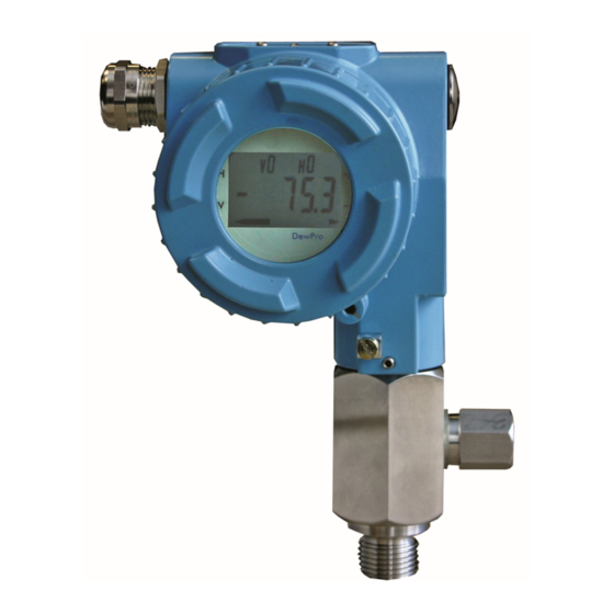
1.3.1 Unit Description The DewPro MMY30 trace moisture transmitter (shown in Figure 2 below) is a loop-powered dewpoint measuring device. The transmitter includes a sensor element, a flow chamber, a weather-proof enclosure, microprocessor electronics, and assorted fittings, all in a compact assembly. In most cases, either the inlet or outlet port includes an orifice to regulate the flow. -
Page 12: Theory Of Operation
4 to 20 mA Loop The DewPro MMY30 transmitter is powered by a DC voltage supply from 12 to 28 VDC. At the nominal 24 VDC supply, the maximum loop resistance is 600 ohms. The signal is represented by the 4 to 20 mA loop current and is directly proportional to the dewpoint range in °C or °F. -
Page 13: Dimensions
Choose a mounting location which allows enough clearance for the use of tools and for connection of the field validator. Figure 3 below shows the dimensions of the standard DewPro MMY30, and Figure 4 on page 6 shows the DewPro MMY30 with the optional display/user interface. - Page 14 Chapter 1. General System Information 1.92 (48) Figure 4: DewPro MMY30 Dimensions with Optional Display/User Interface ® DewPro MMY30 User’s Manual...
-
Page 15: Chapter 2. Installation Guidelines
Take all necessary precautions when mounting or removing the DewPro MMY30. • Mount the DewPro MMY30 vertically whenever possible to prevent solid particles or condensation from entering the bypass line. • Mount the DewPro MMY30 downstream from a shut-off valve to depressurize the DewPro MMY30 when removing it from the process pipe for maintenance or field compensation. -
Page 16: Method I - Orifice At Outlet
Air Flow The DewPro MMY30 is designed to measure the pressure dewpoint. By restricting the flow at the outlet of the integral bypass with an orifice, the sensor monitors the dewpoint at process pressure. The flow rate of the bleed-off air to the atmosphere at 7-8 bar (100 psig), is approximately 70 cc/min (28 L/h / 1.0 SCFH). -
Page 17: Method Ii - Orifice At Inlet
Chapter 2. Installation Guidelines Method II - Orifice at Inlet Figure 6 below illustrates installation of the DewPro MMY30 at the inlet orifice. Figure 6: DewPro MMY30 Installation at Inlet Orifice ® DewPro MMY30 User’s Manual... -
Page 18: Method Iii - No Flow Restriction
Low-pressure, closed-loop drying systems, which are very common with hopper dryers in the plastics industry, operate at very low pressures of a few inches of water. The air passing through the DewPro MMY30 bypass line is fed back to the main stream after a pressure drop in the main line. In this configuration, the DewPro MMY30 bypass has no flow restriction at either the inlet or the outlet.The outlet is equipped with a 1/4”... -
Page 19: Method Iv - Bypass Installation
Method IV - Bypass Installation In some cases there may not be enough room to install the DewPro MMY30 directly to the process pipe. The tube connection at the inlet enables mounting the DewPro MMY30 at a remote location. Any of the functions described for Methods I-III can be selected. - Page 20 (165 mm) 2.76 in. (70 mm) 3.23 in. (82 mm) 0.79 in. (20 mm) 4.45 in. 2.95 in. (113 mm) (75 mm) Horizontal Pipe Mounting Horizontal Pipe Mounting Figure 9: DewPro MMY30 with Various Mounting Brackets ® DewPro MMY30 User’s Manual...
-
Page 21: Chapter 3. Wiring Instructions
Proper handling procedures must be observed during the removal, installation, or other handling of internal circuit boards or devices. Note: If the DewPro MMY30 is equipped with an optional display/user interface, refer to Chapter 4. System Configuration 3.2.1 Various Power Supplies Figure 10 below illustrates various power supplies and displays for use with the DewPro MMY30. -
Page 22: Designing The Loop
Designing the Loop When selecting a power supply, please note that the voltage at the +/- terminal of the DewPro MMY30 should not fall below 12 VDC. The maximum loop resistance is an important parameter for selection of the supply voltage. Each device connected to the loop causes a voltage drop. -
Page 23: Mounting In Environments With Severe Electrical Noise
IMPORTANT: For use of the DewPro MMY30 in environments with severe electrical noise, refer to the specifications in Chapter 6. A shielded, two-wire cable (as shown in Figure 12 below) can be used to interconnect the DewPro MMY30 with the power source. -
Page 24: Electrical Connections
To meet EMI/RFI immunity requirements, a two-wire shielded cable with a common foil shield layer must be used to power the MMY30. Remove 3” of the cable insulation and pull back the foil so that it is clamped in the metal cable gland. The ground wire must be connected to the internal DewPro MMY30 grounding screw. ®... -
Page 25: Chapter 4. Optional Display/User Interface (Option G Or H)
4.1.1 DewPro MMY30 with Display Assembly Unscrew and remove the protective lid from the top of the DewPro MMY30 (as shown in Figure 14 above), exposing the display module below. The buttons V, H, + and – are now accessible. -
Page 26: Description Of The Dewpro Mmy30 Programming Matrix
Figure 15: The MMY30 Optional Display The display of the DewPro MMY30 continuously shows the current matrix location using the vertical (V) and horizontal (H) coordinates to designate the row and column, respectively. The bar graph represents the output current in an analog fashion (see Figure 15 above). -
Page 27: Matrix Programming
Chapter 4. Optional Display/User Interface (Option G or H) Matrix Programming “V” “H” Navigating through the matrix is accomplished by using the buttons to move to another row or column, as shown in the example below. At any location where a value may be changed by the user, the desired value is programmed using the “+”... -
Page 28: Functions Of The Matrix
Note: When switching to ppm , the display may indicate an error “3” if the dewpoint reading is above –20°C. (e.g., the DewPro MMY30 is exposed to ambient air.) 4.5.1.3 Loop at Fault VH 07 If any fault malfunction occurs, the loop can be set to either “–10%”... -
Page 29: Special Calibration
Chapter 4. Optional Display/User Interface (Option G or H) 4.5.2 Special Calibration 4.5.2.1 Adjusting the Pressure Constant VH 30 The process pressure constant is entered in bar (absolute), which is used to calculate ppm . The moisture unit ppm is the ratio of water vapor pressure to the total process pressure and is, therefore, independent of the process pressure. -
Page 30: Mode Of Operation
Chapter 4. Optional Display/User Interface (Option G or H) 4.5.3 Mode of Operation 4.5.3.1 Input Locking VH 89 Any number other than “50” will lock the instrument settings from inadvertent or unauthorized changes. (The instrument is only unlocked at a value of “50.”) 4.5.3.2 Displaying the Present Error Code VH 90 In the event of a system fault, this field displays the diagnostic error code for the fault encountered. - Page 31 Chapter 4. Optional Display/User Interface (Option G or H) 4.5.3.6 Set to Default Values VH 94 This field resets all factory defaults. Note: Anything that has been calibrated will not be reset. 4.5.3.7 Resetting the Device VH 99 The device is reset in this field by entering a value of “50.”...
- Page 32 Chapter 4. Optional Display/User Interface (Option G or H) [no content intended for this page] ® DewPro MMY30 User’s Manual...
-
Page 33: Chapter 5. Troubleshooting
If the dewpoint is below –90°C (–130°F), the current will go below 4 mA and then to 22 mA as the fault current. Expose the DewPro MMY30 to ambient air for several minutes. If the error remains, the cause may be a defective sensor assembly or an electronics malfunction. - Page 34 Chapter 5. Troubleshooting [no content intended for this page] ® DewPro MMY30 User’s Manual...
-
Page 35: Chapter 6. Technical Specifications
Chapter 6. Technical Specifications Chapter 6. Technical Specifications MMY30 Specifications Sensing Element capacitive measurement, planar aluminium oxide sensor Measurement Range –90°C to +10°C DP (dewpoint temperature) –130°F to +50°F DP 0 to 1000 ppm (fully adjustable with integral display option) Recommended Recalibration Cycle 12 months, depending on the application Calibration Accuracy... -
Page 36: Optional Onboard Display With User Interface
1.5 kg (3.2 lb) European Union Compliance (CE) Hereby, Panametrics / Baker Hughes, declares that this equipment is in compliance with EU Directives 2014/30/EU & 2014/34/EU. The full text of the EU declaration of conformity is available at the following internet address: https:www.bakerhughes.com/downloads and search for MMY30. -
Page 37: Hazardous Area Approvals (Optional)
Dust-ignitionproof, Class II and III, Division 1,Groups E, F and G, Type 4X, T5 Ta = 60°C (FM Approvals) • MMY30-Fxxxx: Non-Sparking apparatus for ATEX Zone 2, II 3 G Ex nA IIC T4 (ATEX declaration by the manufacturer (Panametrics) ® DewPro MMY30 User’s Manual... - Page 38 Chapter 6. Technical Specifications [no content intended for this page] ® DewPro MMY30 User’s Manual...
-
Page 39: Appendix A. User Interface Matrix Input
Appendix A. User Interface Matrix Input Appendix A. User Interface Matrix Input Table 3 on page 32 shows the complete DewPro MMY30 programming matrix. ® DewPro MMY30 User’s Manual... - Page 40 Appendix A. User Interface Matrix Input Table 3: Matrix Input for Programming MMY30 Display Select Units Loop #1 at Moisture Value Fault 0 = °C 0 = -10% 1 = °F 1 = 110% 35 = ppm 2 = Hold Dewpoint °C Dewpoint °C at 4 mA...
- Page 41 • If Panametrics determines that the damage is not covered under the terms of the warranty, or if the warranty has expired, an estimate for the cost of the repairs at standard rates will be provided. Upon receipt of the owner’s approval to proceed, the instrument will be repaired and returned.
- Page 42 Warranty [no content intended for this page] ® DewPro MMY30 User’s Manual...
- Page 43 Contact Us! • Break/fix technical support issues for a prod- Global Technical Support Team uct you currently have Email: mstechsupport@bakerhughes.com Phone: 8000-833-9438, option 3. • RMA Repair Requests, Calibration Requests, International - Baker Hughes Customer care Document and Certificate requests for a mstechsupport@bakerhughes.com Email: product you currently have...
Need help?
Do you have a question about the DewPro MMY30 and is the answer not in the manual?
Questions and answers