Advertisement
Quick Links
Advertisement

Subscribe to Our Youtube Channel
Related Manuals for Panametrics PanaFlow LZ


Summary of Contents for Panametrics PanaFlow LZ
- Page 1 PanaFlow™ LZ User’s manual 910-316 Rev. A September 2017...
- Page 2 [no content intended for this page]...
- Page 3 Terms and conditions WARNING! Panametrics’ sales terms and conditions for your recent purchase of a Panametrics product, including the This symbol indicates a risk of potential applicable product warranty, can be found on our website...
- Page 4 (Directive 2011/65/EU). regulations, or laws applicable to safety. Waste Electrical and Electronic Equipment (WEEE) directive Working area Panametrics is an active participant in Europe’s Waste Electrical and Electronic Equipment (WEEE) take-back WARNING! initiative (Directive 2012/19/EU). Auxiliary equipment may have both manual and automatic modes of operation.
-
Page 5: Table Of Contents
Specifications ..................12 2.0 Introduction To ensure safe and reliable operation of the PanaFlow LZ WARNING! -
Page 6: Unpacking The Panaflow Lz System
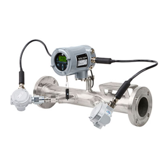
Identification flow transmitters, the photographs used in this manual may appear slightly different The PanaFlow LZ meter has up to three separate labels for from your system. However, the basic identification, depending on its configuration. The system instructions are valid for all PanaFlow LZ is mounted as a single unit.The six keys on the magnetic... -
Page 7: Site Considerations
4.0 Site considerations Local mounting The flow transmitter accuracy is affected by the flowcell location in the process piping and on the orientation of the transducers. Thus, in addition to accessibility for maintenance, adhere to the following installation guidelines: • Locate the flowcell so that there are at least 10 pipe diameters of straight, undisturbed flow upstream and 5 pipe diameters of straight, undisturbed flow downstream from the measurement point (see Figure 2 below). - Page 8 4.2 Remote mounting 4.5 Insulation The standard flow transmitter enclosure is a powder- Do not place thermal insulation on or around the transducer coated, aluminum, IP67 explosion-proof enclosure. locations or the flow transmitter. The enclosures act as heat Typically, the enclosure is mounted as close as possible sinks that protect against high and low temperatures.
-
Page 9: Installing Cable Glands
5.0 Installing cable glands When wiring the PanaFlow LZ system in accordance with the instructions in the flow transmitter User’s Manual, it is essential that the cable glands be properly installed. To accomplish this, carefully complete the following steps: WARNING! Failure to properly install the cables in the glands will compromise the environmental ratings of the PanaFlow LZ system. - Page 10 5.0 Installing cable glands (cont.) 3. Tighten the Threaded Entry (see Figure 6 below) with a wrench to form a permanent joint. Figure 6: Tightening the threaded entry 4. Insert the Coaxial Cable into the Threaded Entry (see Figure 7 below). Figure 7: Inserting the coaxial cable into the threaded entry...
- Page 11 5.0 Installing cable glands (cont.) 5. Push the Coaxial Cable into the gland until the Armor Clamp is fully inserted into the Threaded Entry section. (see Figure 8 below). Figure 8: Inserting the armor clamp into the gland 6. Screw the Middle Nut onto the cable gland to secure the clamped section (see Figure 9 below). Figure 9: Installing the middle nut...
- Page 12 5.0 Installing cable glands (cont.) 7. Tighten the Middle Nut completely by hand (see Figure 10 below). Figure 10: Tightening the middle nut by hand 8. Tighten the Middle Nut with a wrench, but be very careful not to overtighten the nut or the Armor Wires may be broken (see Figure 11 below).
- Page 13 5.0 Installing cable glands (cont.) 9. Screw the Back Nut over the Retaining Collar (see Figure 12 below). Figure 12: Screwing the back nut over the retaining collar 10. Hand tighten the Back Nut to secure the Coaxial Cable and make a weather-tight seal (see Figure 13 below). Figure 13: Tightening the back nut by hand...
- Page 14 5.0 Installing cable glands (cont.) 11. Slide the Rubber Boot down the cable and over the Cable Gland Assembly (see Figure 14 below). Figure 14: Sliding the rubber boot over the cable gland assembly 12. Make sure the Rubber Boot completely covers the Cable Gland and that no tears have occurred in the boot during the assembly process (see Figure 15 below).
- Page 15 (see Figure 16 below) as follows: Attention! Because the PanaFlow LZ system has the flexibility to use several different Panametrics flow transmitters, the photographs used in this manual may appear slightly different from your system. However, the basic instructions are valid for all PanaFlow LZ systems.
-
Page 16: Specifications
6.0 Specifications Operation and performance 6.2 Electronics/flow transmitter Fluid types Temperature range Liquids: acoustically conductive fluids, including most clean Operating: -40 to 140°F (-40 to +60°C) liquids, and many liquids with small amounts of entrained Storage: -67 to 167°F (-55 to 75°C) solids or gas bubbles Flow measurement Correlation Transit Time model... - Page 17 Drawing Description Temperature range WT Transducers:- 40 to 175°C (-40 to 347°F) General arrangement drawing, PanaFlow LZ, 712-2122 BWT Transducers: -40 to 100°C (-40 to 212°F) 6” and 3”, 1 path, 2 traverse, tilted diameter -40 to 250°C (-40 to 482°F) General arrangement drawing, PanaFlow LZ, Temperature rating of -20°C if used with carbon steel meter...
- Page 18 6.3 Transducer cables Integral Cables • Mineral insulated cables with potted cable glands (for North America & Canada hazardous locations) • Armored flame retardant coaxial cables with ATEX/IECEx certified cable glands (for European hazardous locations) Remote Cables ATEX/IECEx: Armored RG-62 for ATEX/IECEx US/CAN: Non-armored RG-62, conduit not included Remote cables are not included and must be ordered separately.
- Page 20 Experts in flare management, Panametrics technology also reduces flare emissions and optimizes performance. With a reach that extends across the globe, Panametrics’ critical measurement solutions and flare emissions management are enabling customers to drive efficiency and achieve carbon reduction targets across critical industries including: Oil &...
Need help?
Do you have a question about the PanaFlow LZ and is the answer not in the manual?
Questions and answers