
Subscribe to Our Youtube Channel
Related Manuals for Panametrics XDP-H2


Summary of Contents for Panametrics XDP-H2
- Page 1 XDP-H2 Panametrics Explosion-Proof Display Package User’s Manual Attention! This manual is for use with XDP units with H2 software (E=2) only. 910-204 Rev. B2 panametrics.com July 2022...
- Page 3 • If Panametrics determines that the damage is not covered under the terms of the warranty, or if the warranty has expired, an estimate for the cost of the repairs at standard rates will be provided. Upon receipt of the owner’s approval to proceed, the instrument will be repaired and returned.
- Page 4 Warranty [no content intended for this page] XDP-H2 User’s Manual...
-
Page 5: Table Of Contents
4.10.4 Viewing and Clearing the Cal Drift..............4-20 XDP-H2 User’s Manual... - Page 6 XDP Alarm Relays ....................B-2 Appendix C. Menu Maps XDP-H2 User’s Manual...
- Page 7 A Typical Application........... 1-4 XDP-H2 User’s Manual...
-
Page 8: Chapter 1. General Information
Introduction The XDP Explosion-proof Display Package has been designed as one component of a system that monitors the composition of a binary gas. The second component is a remotely-mounted sensor/transmitter, such as the Panametrics Model TMO2-TC or similar device. Note: Refer to the documentation supplied with the specific transmitter used for complete information on the transmitter. -
Page 9: System Overview
The XDP accepts the 4-20 mA analog input from the transmitter and processes the information. Then, the results are displayed on the built-in digital display window. In addition, the data may be output as a linear analog signal to drive a data recorder and/or controller device. XDP-H2 User’s Manual... -
Page 10: A Typical Application
• 0-100% air in carbon dioxide Panametrics offers several transmitters that are well suited for operation in all of these environments, and the XDP has been designed to permit quick and easy switching between the analysis and display of these three gas mixture inputs. -
Page 11: Chapter 2. Installation
Wiring the XDP ............2-3 XDP-H2 User’s Manual... -
Page 12: Introduction
Choosing an All environmental and installation factors should have been discussed with a Panametrics applications engineer or field sales person at the time the XDP was Installation Site ordered. Thus, the equipment should be suited to the application and the planned installation site. -
Page 13: Mounting The Xdp System
Note: A suitable sample system may be ordered directly from Panametrics. The sample system would be supplied fully assembled on a flat plate with four (4) mounting holes. See the sample system and/or transmitter manuals for more details. -
Page 14: Wiring The Remote Transmitter - J6
Connect the XDP Low alarm as follows (this alarm is factory-configured in failsafe mode, but may be reconfigured): Connect pin #7 (NC) to the alarm device input. Connect pin #8 (C) to the alarm device return. Pin #9 (NO) is not used for fail-safe operation. XDP-H2 User’s Manual... -
Page 15: Wiring The Xdp Analog Output - J8
To wire the serial port, complete the following steps: - J4 Note: This connection may be made with a Panametrics #704-668 cable. If this cable is used, pin #1 is the red wire, pin #2 is the white wire, and pin #3 is the green wire. - Page 16 Figure 2-10 on page 8. Make sure that the factory-installed jumper wire at pin G on the power connector is secure. This completes the wiring of the XDP. Proceed to Chapter 3, Operation, for instructions on using the meter. XDP-H2 User’s Manual...
- Page 17 8.23 (209) 9.14 (232) 5.60 (142) 10.54 (268) 3.00 5.00 (76) (127) 4.99 (127) 6.00 (152) NOTE: DIMENSIONS ARE IN INCHES (MILLIMETERS). 8.00 (203) XDP-H2 User’s Manual...
- Page 18 Normal (C) Normal (NO) Fault (NC) Fault (C) No connections Fault (NO) required here. [* wire colors for Panametrics Low (NC) # 704-668 serial cable] (See Appendix B) SYSTEM ANALOG OUTPUT - J5 SYSTEM FAULT ALARM - J2 Low (C)
-
Page 19: Chapter 3. Operation
Error Messages............3-6 XDP-H2 User’s Manual... -
Page 20: Introduction
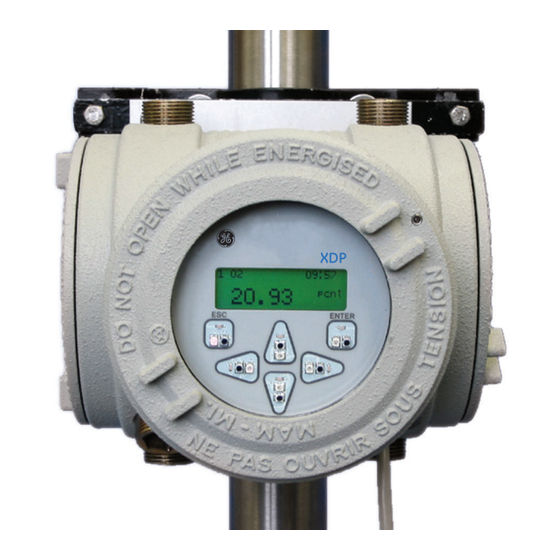
1.8 m (6 ft) of the unit. 3.4.1 The Digital Display The digital display window at the top of the XDP enclosure includes the components Window shown in Figure 2 below. XDP-H2 User’s Manual... -
Page 21: Initial Screen Displays
This is a typical example of the first initialization screen. Boot is Flash. Program CRC valid. Booting from Flash Scanning Hardware This is a typical example of the second initialization screen. Found Image Slot 1 Downloading Slot 1 XDP-H2 User’s Manual... - Page 22 Low Low alarm, and this screen appears. Low Low H2 pcnt +XX.X Note: The padlock icon at the upper right hand corner of the above displays indicates that the User Program is locked with password protection. XDP-H2 User’s Manual...
-
Page 23: Starting The Sample Gas
Then, use [] and [] Enter Password to increment the value. Press [ENTER] when done. XXXX Disp This screen shows the highest level of the User Program, which is referred to as the main menu. XDP-H2 User’s Manual... -
Page 24: Exiting The User Program
Table 1 on page 7. IMPORTANT: Table 1 on page 7 lists the error messages in order of priority. If multiple errors occur simultaneously, only the highest priority error is displayed (errors with the same priority level cannot occur simultaneously). XDP-H2 User’s Manual... - Page 25 Occurs in H2/AIR This indicates air contamination, and the no response pct: measurement Low-Low Alarm will trip. Remove the mode, when the source of the air contamination. H2 reading is below the Low-Low Alarm setpoint (usually 80%). XDP-H2 User’s Manual...
- Page 26 Chapter 3. Operation [no content intended for this page] XDP-H2 User’s Manual...
-
Page 27: Chapter 4. Setup And Calibration
Calibrating the System..........4-17 XDP-H2 User’s Manual... -
Page 28: Introduction
H2/CO2 curve. To select the Active Curve XDP active curve, access the User Program as described on page 3-4, and proceed as follows: Disp Use the [] and [] keys to select [Cal] and press [ENTER]. XDP-H2 User’s Manual... -
Page 29: Switching Display Windows
Program as described on page 3-4 and proceed as follows: Note: As a shortcut, the display windows may be switched from normal run mode by using the [] and [] keys. Disp Use the [] and [] keys to select [Disp] and press [ENTER]. XDP-H2 User’s Manual... -
Page 30: Adjusting The Display Contrast
Use the [] and [] keys to select [User] and press [ENTER]. User Lock Menus Note: “Lock All” and “Versions” menu options also appear on the above list. Use the [] and [] keys to select [Contrast] User and press [ENTER]. Analog Output Contrast Backlight XDP-H2 User’s Manual... -
Page 31: Setting The Display Backlight
The “Fault Alarm” and “Analog Output” options are also available in the above list box. The display backlight has three possible settings: • Off - the backlight is permanently turned off • On - the backlight is continuously on XDP-H2 User’s Manual... -
Page 32: Setting The System Fault Alarm
User Program, as described on page 3-4, and proceeding as follows: Alarm Note: See Appendix B, Additional Wiring Connections, for instructions on wiring the system fault alarm. Disp Use the [] and [] keys to select [Opt] and press [ENTER]. XDP-H2 User’s Manual... -
Page 33: Setting Up The System Analog Output
User Program, as System Analog described on page 3-4, and proceeding as follows: Output Note: See Appendix B, Additional Wiring Connections, for instructions on wiring the system analog output. XDP-H2 User’s Manual... -
Page 34: Choosing The System Analog Output Type
Use the [] and [] keys to select [Aout User Aout Type], and press [ENTER]. Aout Type Zero Setpoint Span Setpoint Note: The Test, Zero Trim, and Span Trim options are also available in the above list box. XDP-H2 User’s Manual... -
Page 35: Setting The Zero Setpoint
You are now back at the system analog output setup menu. Aout Type Zero Setpoint Span Setpoint Either press [ESC] until you return the User Menu or proceed to the appropriate section to continue setting up the system analog output. XDP-H2 User’s Manual... -
Page 36: Setting The Span Setpoint
At the next prompt, enter the desired “Test Percent” value, which is the system analog output value (expressed as a percentage of the system analog output span) used by the meter as a TEST signal. 4-10 XDP-H2 User’s Manual... -
Page 37: Setting The Zero Trim
At the following prompt, the system analog output of the meter is driven at exactly the low end of the output range. User Aout Zero-Trim Press the [] and [] key until your output device reads the correct value. When done, Zero Trim press [ENTER]. XDP-H2 User’s Manual 4-11... -
Page 38: Setting The Span Trim
You are now back at the system analog output setup menu. Test Zero Trim Span Trim Either press [ESC] until you return the User Menu or proceed to the appropriate section to continue setting up the system analog output. 4-12 XDP-H2 User’s Manual... -
Page 39: Setting Up The Serial Port
At the following prompt, choose one of the following baud rates: 300, 1200, 2400, 9600, 19200, 38400, 57600, or 115200. User Node..Baud-Rate Use the [] and [] keys to select the desired baud rate and press [ENTER]. 9600 19200 38400 XDP-H2 User’s Manual 4-13... -
Page 40: Other Opt Menu Options
To accomplish this, access the main menu as described on page 3-4, and proceed as follows: Note: If the meter is powered down, the password protection is in effect by default when the meter is powered up. 4-14 XDP-H2 User’s Manual... -
Page 41: Lock All
Lock All Versions Note: The “User” menu option is also available above. The meter returns directly to run mode, with 1 H2/AIR the padlock icon indicating that the User 91.52 pcnt Program is now locked. XDP-H2 User’s Manual 4-15... -
Page 42: Versions
Disp Press [ESC] to return to the main menu. Lock Menus Lock All Versions Press [ESC] until you exit the User Program, or proceed to the appropriate section of this chapter to continue programming the meter. 4-16 XDP-H2 User’s Manual... -
Page 43: Calibrating The System
To perform a field calibration of the meter, access the main menu of the User Calibration Program (see page 3-4) and proceed as follows: Disp If necessary, use the [] and [] keys to select [Cal] and press [ENTER]. Press [ENTER]. Disp 1:Cal XDP-H2 User’s Manual 4-17... - Page 44 [NO] response sends the calibration gas value to the analog output. Gas-Curve: Man..Cal Use [] and [] highlight the desired answer (YES or NO) to the question shown. Then, press Hold 4-20 mA Output the [ENTER] key. During Calibration? 4-18 XDP-H2 User’s Manual...
-
Page 45: Performing A Span Calibration
Press [ENTER] when done. xxx.xx A [YES] response at the next prompt sends the last live value to the analog output, while a [NO] response sends the calibration gas value to the analog output. XDP-H2 User’s Manual 4-19... -
Page 46: Viewing And Clearing The Cal Drift
The XDP internally monitors the amount of drift from the factory calibration, and the Clearing the Cal operator may view the drift values and clear them, if desired. To accomplish this, access the main menu of the User Program (see page 3-4) and proceed as follows: Drift 4-20 XDP-H2 User’s Manual... - Page 47 Use the [] and [] keys to select [Clear Cal Drift] and press [ENTER]. View-Cal-Drift Clear-Cal-Drift Clear-Cal-Drift Use [] and [] highlight the desired answer (YES or NO) to the question shown. Then, press Clear Drift? Warning the [ENTER] key. Data Will Be Reset! XDP-H2 User’s Manual 4-21...
- Page 48 Press [ESC] to return to the Cal Menu. View-Cal-Drift Clear-Cal-Drift Press [ESC] as many times as necessary to return to normal RUN mode, or proceed to the appropriate section of this chapter to continue programming the XDP. 4-22 XDP-H2 User’s Manual...
- Page 49 Exiting the User Program ..........5-17 XDP-H2 User’s Manual...
-
Page 50: Chapter 5. Advanced Programming
Low and Low Low alarms • testing all XDP alarms 5.3.1 Configuring the After powering up, the XDP performs a series of internal tests. If the display has not Display yet been configured, the following screen appears: XDP-H2 User’s Manual... - Page 51 [ENTER] to select this range. (H2/AIR is used H2/AIR here as an example.) From 1:Cfg H2/AIR A list of available units is shown. Use the [] and [] keys to select the desired units and press [ENTER]. pcnt XDP-H2 User’s Manual...
-
Page 52: Accessing The Setup Menu
Chapter 4, Setup and Calibration. Also, the display may be reconfigured at any time by repeating the above procedure. 5.3.2 Accessing the To access the setup menu from the main menu of the User Program, proceed as Setup Menu follows: Disp Use the [] and [] keys to select [Cal]. XDP-H2 User’s Manual... -
Page 53: Configuring The 4-20 Ma Xdp Analog Output
Use the [] and [] keys to select the desired output range and press [ENTER]. H2/AIR H2/CO2 AIR/CO2 Note: The H2/AIR range is used in this manual as an example. To program the other ranges, use similar procedures. XDP-H2 User’s Manual... - Page 54 When Enter-mA-Value done, press [ENTER]. xx.xx The above two prompts repeat so that more than one test value may be tried. When the testing is complete, press [ESC] from the first prompt to leave the Test submenu. XDP-H2 User’s Manual...
- Page 55 5-4 and complete the following steps: Alarms Setup Range Use the [] and [] keys to select [Alarms] and press [ENTER]. 4-20mA-Out Alarms Note: The other six alarm relays listed in the alarm setup menu are discussed in the next section. XDP-H2 User’s Manual...
- Page 56 Trip Reset The program alternates between the two previous prompts, each time [ENTER] is pressed. To leave the test loop, press [ESC]. Note: Upon leaving the test loop, the alarm is automatically reset to its normal state. XDP-H2 User’s Manual...
- Page 57 Use [] and [] to position the cursor under the desired character. Then, use [] and [] Trip-Point to increment the value. Press [ENTER] when done. xxx.xx Use the [] and [] keys to select [Test] and Ala..Low-Low-Alarm press [ENTER]. Trip-Point Test Fail-Safe XDP-H2 User’s Manual...
- Page 58 Alarms Press [ESC] to return to the setup menu. Low-Alarm Low-Low-Alarm Normal-Alarm To continue programming the setup menu, proceed to the appropriate section for instructions. Otherwise, press [ESC] four times to return to live measurement mode. 5-10 XDP-H2 User’s Manual...
- Page 59 Alarms Norma..Test press [ENTER]. Trip Reset After verifying that the alarm has actually tripped, continue to the next prompt. Alarms Norma..Test If necessary, use the [] and [] keys to select [Reset] and press [ENTER]. Trip Reset XDP-H2 User’s Manual 5-11...
-
Page 60: Factory-Level Programming
At the next prompt, enter serial number of the transmitter, as provided by Panametrics. Sensor-Serial-Num Use [] and [] to position the cursor under the desired character. Then, use [] and [] Sensor-Serial-Num to increment the value. Press [ENTER] when done. xxxxx 5-12 XDP-H2 User’s Manual... - Page 61 5-5) and connect the XDP analog output signal to the analog input terminals. Use the [] and [] keys to select [Trim] and 4-20mA-Input press [ENTER]. Test Trim The XDP analog output is now driven to exactly 4 mA. XDP-H2 User’s Manual 5-13...
-
Page 62: Entering Factory Calibration Data
Gas Curve: Use the [] and [] keys to select [H2/AIR] and press [ENTER]. H2/AIR H2/CO2 AIR/CO2 At the next prompt, enter the number of data points available for calibrating the chosen gas curve. 5-14 XDP-H2 User’s Manual... - Page 63 Press [ESC] to return to the setup submenu. Gas-Curve: H2/AIR H2/CO2 AIR/CO2 To continue programming the setup menu, proceed to the appropriate section for instructions. Otherwise, press [ESC] four times to return to live measurement mode. XDP-H2 User’s Manual 5-15...
-
Page 64: Loading Software
Use the [] and [] keys to select [Load Slot] and press [ENTER]. Load Slot Load Main Setup Load-Slot Press [ENTER]. 1:Load When the download is complete, the meter automatically reboots into run mode. Size: Received Block: Write to Slot 1 5-16 XDP-H2 User’s Manual... -
Page 65: Exiting The User Program
When you have finished programming all of the required functions, press [ESC] as Program many times as necessary to return to normal run mode. The number of key presses required depends on which feature was programmed last. The XDP may then be placed into service. XDP-H2 User’s Manual 5-17... - Page 66 Chapter 5. Advanced Programming [no content intended for this page] 5-18 XDP-H2 User’s Manual...
-
Page 67: Chapter 6. Xdp Specifications
Transmitter Specifications ..........6-3 XDP-H2 User’s Manual... -
Page 68: Performance Specifications
Power Input: 100-240 VAC; 50/60 Hz; 40 W max. Power Output to Transmitter: 24.0 ± 2.0 VDC; 1 A max. Note: The power supply meets CISPR 55022 and CISPR 55014, Level B EMI requirements and IEC1010-1 safety standards. XDP-H2 User’s Manual... -
Page 69: Functional Specifications
73/23/EEC Low Voltage Directive (Installation Category II, Pollution Degree 2). It is in compliance with ATEX directive 94/9/EC Annex II, per the document at the back of this manual. Transmitter For complete transmitter specifications, refer to the documentation provided with the transmitter. Specifications XDP-H2 User’s Manual... - Page 70 Chapter 6. XDP Specifications [no content intended for this page] XDP-H2 User’s Manual...
-
Page 71: Appendix A. Ce Mark Compliance
LVD Compliance ............A-2 XDP-H2 User’s Manual... -
Page 72: Introduction
The disconnect device must be marked as such, clearly visible, directly accessible, and located within 1.8 m (6 ft) of the XDP. Note: If the instructions in this appendix are followed, the unit will comply with the Low Voltage Directive (73/23/EEC). XDP-H2 User’s Manual... -
Page 73: Appendix B. Additional Wiring Connections
XDP Alarm Relays ............B-2 XDP-H2 User’s Manual... -
Page 74: Introduction
• Gas Curve Relay 2 • Process/Cal Relay • Zero/Span Relay Note: Contact Panametrics for information on the use and functions of these alarms. Table 2: Terminal Block J7 Connections Pin # Alarm Terminal Gas Curve Relay 1 Gas Curve Relay 2... - Page 75 (NO) contacts. For non-fail-safe operation, connect pin #1 to the alarm input. Connect pin #2 to the alarm device return. For fail-safe operation, connect pin #3 to the alarm input XDP-H2 User’s Manual...
- Page 76 Appendix B. Additional Wiring Connections [no content intended for this page] XDP-H2 User’s Manual...
- Page 77 Factory-Level Menu Map ..........C-6 XDP-H2 User’s Manual...
- Page 78 Appendix C. Menu Maps XDP-H2 User’s Manual...
- Page 79 H2/AIR mA H2/AIR Select-Active-Curve Manual Cal H2/AIR Zero Span H2/CO2 H2/CO2 Zero/Span Drift Hold Output? Hold Output? AIR/CO2 View-Cal-Drift Clear-Cal-Drift Clear Drift? Introduce Cal Gas Introduce Cal Gas Next When Stable Next When Stable Span Drift Zero Drift XDP-H2 User’s Manual...
- Page 80 Contrast Span Setpoint 0-2V 91.52 pcnt Backlight Lock All Test Namur Versions Software Versions Comm Zero Trim Span Trim Timed Data Length* Node ID* Baud Rate* [* see text for available options] Parity* Stop Bits* Comm Type* XDP-H2 User’s Manual...
- Page 81 Trip-Point 4-20mA-Out Low-Alarm Pcnt Alarms Low-Low-Alarm Test Trip 0:Display 0:Fault Alarm* 0:Analog Output* [* system functions] Normal-Alarm Fail-Safe Reset H2/AIR XDP-Fault-Alarm Non-Fail-Safe H2/CO2 Gas-Curve-Relay1 Fail-Safe 4-20_Out_Range Gas-Curve-Relay2 AIR/CO2 Test mA Test Process/Cal-Relay Test Trip Zero/Span-Relay Trim Reset XDP-H2 User’s Manual...
- Page 82 91.52 pcnt Disp 1:Cal User Range Setup Setup Load Slot 4-20mA-Out Lock Menus Load Main Alarms Lock All Trim Serial Number Versions mA Input Test Test 4-20mA Input 1:Load H2/AIR Factory Calibration H2/CO2 91.52 pcnt AIR/CO2 XDP-H2 User’s Manual C-10...
- Page 83 DECLARATION CONFORMITY Panametrics Limited Shannon Industrial Estate Shannon, County Clare Ireland declare under our sole responsibility that the XDP Explosion-Proof Display Package to which this declaration relates, are in conformity with the following standards: • EN 61326:1998, Class A, Annex A, Continuous Unmonitored Operation (For EN 61000-4-3, the above units meet performance Criteria A, and in a limited number of frequencies, performance Criteria B per EN 61326.)
- Page 84 DÉCLARATION CONFORMITÉ Nous, Panametrics Limited Shannon Industrial Estate Shannon, County Clare Ireland déclarons comme étant de notre seule responsabilité que les produits Unité d’affichage antidéflagrante XDP sur lesquels porte ce document, sont conformes aux spécifications suivantes: • EN 61326:1998, Classe A, Annexe A, Fonctionnement continu sans surveillance (Pour EN 61000-4-3, les appareils ci-dessus sont conformes au critère A de performance et, dans un nombre limité...
- Page 85 KONFORMITÄTS- ERKLÄRUNG Wir, Panametrics Limited Shannon Industrial Estate Shannon, County Clare Ireland erklären unter alleiniger Eigenverantwortlichkeit, dass die Produkte XDP explosionsgeschütztes Anzeigegerät auf die sich diese Deklaration bezieht, die folgenden Normen erfüllen: • EN 61326:1998, Class A, Annex A, kontinuierlicher, überwachungsfreier Betrieb (Für EN 61000-4-3 erfüllen die obigen Geräte die Leistungskriterien A und in bei einer begrenzten Anzahl von...
- Page 86 ATEX COMPLIANCE Panametrics 1100 Technology Park Drive Billerica, MA 01821-4111 U.S.A. as the manufacturer, declare under our sole responsibility that the product XDP Explosion-Proof Display Package to which this document relates, in accordance with the provisions of ATEX Directive 94/9/EC Annex II, meets...
- Page 88 Customer Support Centers U.S.A. The Boston Center 1100 Technology Park Drive Billerica, MA 01821 U.S.A. Tel: 800 833 9438 (toll-free) 978 437 1000 E-mail: mstechsupport@bakerhughes.com Ireland Sensing House Shannon Free Zone East Shannon, County Clare Ireland Tel: +353 (0)61 470200 E-mail: mstechsupport@bakerhughes.com Copyright 2022 Baker Hughes company.
Need help?
Do you have a question about the XDP-H2 and is the answer not in the manual?
Questions and answers