Sign In
Upload
Manuals
Brands
Panametrics Manuals
Measuring Instruments
PanaFlow MV80
Panametrics PanaFlow MV80 Manuals
Manuals and User Guides for Panametrics PanaFlow MV80. We have
1
Panametrics PanaFlow MV80 manual available for free PDF download: User Manual
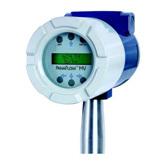
Panametrics PanaFlow MV80 User Manual (184 pages)
Vortex Volumetric and Mass Flow Meters
Brand:
Panametrics
| Category:
Measuring Instruments
| Size: 11 MB
Table of Contents
Table of Contents
9
Chapter 1. Introduction
13
Multi-Parameter Vortex Mass Flow Meters
13
Multi-Parameter Mass Flow Meters
13
Volumetric Flow Meters
13
Using this Manual
13
How the Panaflow Vortex Mass Flow Meter Operates
13
Velocity Measurement
14
Vortex Shedding Frequency
15
Vortex Frequency Sensing
15
Flow Velocity Range
16
Pressure Drop
17
Minimum Back Pressure
17
Temperature Measurement
17
Pressure Measurement
18
Flow Meter Configurations
18
Multivariable Options
18
Line Size, Process Connections and Materials
19
Flow Meter Electronics
19
Chapter 2. Installation
21
Installation Overview
21
Flow Meter Installation Requirements
21
Unobstructed Flow Requirements
22
Recommended Meter Locations
23
Series MV80 In-Line Flow Meter Installation
25
Flange Bolt Specifications
25
Installing Wafer-Style Flow Meters
26
Installing Flange-Style Flow Meters
28
Series MV82 Insertion Flow Meter Installation
29
General Installation Guidelines
29
Electronics Enclosure Clearance
29
Isolation Valve Selection
29
Cold Tap Guidelines
29
Hot Tap Guidelines
31
Insertion Guidelines
33
Selecting the Correct Insertion Formula
33
Installing Flow Meters with a Compression Connection
34
Installing Flow Meters with a Packing Gland Connection
37
Insertion Procedure for Flow Meters with Permanent Insertion Tool
38
Insertion Procedure for Flow Meters with Removable Insertion Tool
40
Installing Flow Meters with a Packing Gland Connection (no Insertion Tool)
42
Adjusting the Meter Orientation
43
Display/Keypad Adjustment (All Meters)
43
Enclosure Adjustment (Series MV80 Only)
44
Loop Power Flow Meter Wiring Connections
46
DC Input Power Connections
46
Ma Output Connections
47
Pulse Output Connections
47
Frequency Output Connections
49
Optional Backlight Connection
49
Remote Electronics Wiring
50
Line Power Meter Wiring Connections
51
Input Power Connections
52
AC Power Wiring
52
DC Power Wiring
52
Ma Output Connections
53
Frequency Output Connections
54
Pulse Output Connections
56
Alarm Output Connections
57
Remote Electronics Wiring
58
Optional Input Wiring
59
Optional Energy EMS RTD Input Wiring
59
Optional External 4-20 Ma Input Wiring
60
Optional External 4-20 Ma Input and RTD Wiring
61
Optional Energy EMS External 4-20 Ma Input and RTD Wiring
62
Optional Contact Closure Input Wiring
62
Meter Initial Setup
63
Power over Ethernet (POE) Wiring Connections
63
DC Power Wiring
63
POE Power Wiring
64
Direct Connection Options
64
Connection Issues
64
Network Configuration
64
IP Setup Network Configuration Tool
65
Configuring the Meter with IP Setup
65
Ipsetup Does Not Display Your Vortex/Tcp Device
65
Ipsetup FAQ
66
Meter WEB
66
WEB Page
67
WEB Configuration Interface
70
2.7.10 Internet Connection to the Meter, Security Issues
73
Modbus/Tcp Interface
74
Modbus Utilities
74
MBGUI.EXE Simple Modbus/Tcp Client
75
Console Modbus/Tcp Client MBUS.EXE
76
2.7.12 Data Logging
77
Dummy Registers Group 9000
81
Other Methods of Retrieving Log Files
82
2.7.13 Update of Firmware
84
Chapter 3. Operating Instructions
85
Pressurization Guidelines
85
Flow Meter Display/Keypad
85
Display Contrast Adjustment
87
Start-Up
87
Using the Setup Menus
89
A Menu Map
89
Programming the Flow Meter
90
The Output Menu
90
Example for Calculating Output Current
91
The Display Menu
92
The Alarms Menu
92
The Totalizer #1 Menu
95
The Totalizer #2 Menu
97
The Energy Menu for EMS Energy Meters Only
98
3.5.10 the Fluid Menu
100
The Units Menu
102
3.5.12 the Time & Date Menu
103
3.5.13 the Diagnostics Menu
104
3.5.14 the Calibration Menu
106
3.5.15 the Password Menu
107
Chapter 4. Serial Communications
109
HART Communications
109
Wiring
109
HART Loop Powered Meter Wiring
109
HART DC Powered Meter Wiring
110
HART AC Powered Meter Wiring
111
HART Commands with the Digital Display Menu
112
HART Commands with the Generic Digital Display Menu
117
Modbus Communications
118
Applicable Flow Meter Models
118
Overview
118
Reference Documents
118
Wiring
119
Pin Labeling Among Devices
119
Menu Items
120
Address
120
Comm Protocol
120
Modbus Units
120
Modbus Order
120
Modbus Protocol
121
Register Definitions
122
Exception Status Definitions
124
Discrete Input Definitions
124
Control Register Definitions
124
Error Responses
125
Command Message Format
125
Normal Response Message Format
125
Exception Response Message Format
125
Examples
126
Bacnet MS/TP Communications
128
Bacnet MS/TP Description
128
Baud Rates on the MS/TP Bus
128
Baud Rate and MAC Address Configuration
128
Supported Bacnet Objects
129
Device Object
131
Analog Input Object
132
Binary Input Objects
134
Binary Value Objects
134
ANNEX - Bacnet Protocol Implementation Conformance Statement
135
Acronyms and Definitions
139
Chapter 5. Troubleshooting and Repair
141
Hidden Diagnostics Menus
141
Level One Hidden Diagnostics Values
143
Column Two Hidden Diagnostics Values
144
Analog Output Calibration
145
Display Contrast Adjustment
145
Troubleshooting the Flow Meter
146
Determine the Fault
148
Symptom: Output at no Flow
148
Symptom: Erratic Output
148
Symptom: no Output
149
Symptom: Meter Displays Temperature Fault
151
Symptom: Meter Displays Pressure Fault
152
Electronics Assembly Replacement (All Meters)
153
Pressure Sensor Replacement (Series MV80 Only)
154
Returning Equipment to the Factory
154
Appendix A. Product Specifications
167
Appendix B. Approvals
167
Appendix C. Flow Meter Calculations
169
In-Line Flow Meter Calculations
169
Volume Flow Rate
169
Mass Flow Rate
169
C.1.3 Flowing Velocity
169
Insertion Flow Meter Calculations
170
Flowing Velocity
170
C.2.2 Volume Flow Rate
170
C.2.3 Mass Flow Rate
170
Energy Flow Calculations
171
C.3.1 Steam Supply, Water Return, Meter Steam Supply
171
C.3.2 Water Supply and Return, Meter Supply
171
C.3.3 Water Supply and Return, Meter Return
171
C.4 Fluid Calculations
171
C.4.1 Calculations for Steam T & P
171
C.4.1A Density
172
C.4.1B Viscosity
173
Calculations for Gas ("Real Gas" and "Other Gas")
173
C.4.2A Density
173
C.4.2B Viscosity
174
C.4.3 Calculations for Liquid
174
C.4.3A Density
174
C.4.3B Viscosity
175
Appendix D. Glossary
177
Advertisement
Advertisement
Related Products
Panametrics PanaFlow MV82
Panametrics PanaFlow MV84
Panametrics MG2
Panametrics MG2-XT
Panametrics MG2-DL
Panametrics DewPro MMR31
Panametrics DewPro MMY30
Panametrics PanaFlow XMT1000
Panametrics PanaFlow LZ
Panametrics PanaFlow FLI
Panametrics Categories
Measuring Instruments
Transmitter
Transducer
Industrial Equipment
Monitor
More Panametrics Manuals
Login
Sign In
OR
Sign in with Facebook
Sign in with Google
Upload manual
Upload from disk
Upload from URL