Table of Contents
Advertisement
Quick Links
Advertisement
Table of Contents

Subscribe to Our Youtube Channel
Related Manuals for Panametrics flare.IQ Generation 2


Summary of Contents for Panametrics flare.IQ Generation 2
- Page 1 flare.IQ Generation 2 Operation and maintenance manual...
- Page 3 flare.IQ Generation 2 Operation and maintenance manual 910-350 rev A June 2020...
- Page 4 [no content intended for this page]...
- Page 5 Product registration Typographical conventions Thank you for purchasing your flare.IQ from Panametrics. Note: These paragraphs provide information that provides Please register your product at https://info.bakerhughes. a deeper understanding of the situation but is not essential com/New-Product-Registration-LP.html for product support to the proper completion of the instructions.
- Page 6 2011/65/EU). regulations, or laws applicable to safety. Waste Electrical and Electronic Equipment (WEEE) directive Working area Panametrics is an active participant in Europe’s Waste Electrical and Electronic Equipment (WEEE) take-back WARNING! initiative (Directive 2012/19/EU). Auxiliary equipment may have both manual and automatic modes of operation.
-
Page 7: Table Of Contents
Contents Chapter 1. General information ............9 Introduction . - Page 8 Chapter 4. Installation and maintenance ..........37 Power distribution.
-
Page 9: Chapter 1. General Information
(see figure 1). The software algorithm in assembly of industrial embedded automation computers. flare.IQ uses the sound speed measured by Panametrics’ The flare.IQ Gen 2 is a complete turnkey hardware and ultrasonic flow meter to calculate the molecular weight... -
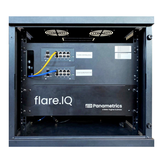
Page 10: Equipment Overview
Equipment overview The system hardware includes two 19” rack mounting WARNING! sheet metal modules that house compact fanless digital A disconnect power switch is required processing units (DPU), redundant power supplies, a pair of to be installed within 30” (2.5 feet) of the ethernet switches and other power distribution equipment rack-mounted panels. -
Page 11: Equipment Installation
You should discuss environmental and installation factors installing electrical equipment in your area. with a Panametrics applications engineer or field service by the time you receive the hardware. The equipment provided should be suited to your application and installation site. -
Page 12: System Specifications
System specifications Installation Operating temperature • 19” rack mountable (enclosed with tool access), • 0°C to +40°C (32°F to +140°F) 2 interconnected modules – top (4U) and bottom (3U) Storage temperature • Flare control software always comes with redundant DPUs (i.e., 2 DPUs/flare); digital verification software •... -
Page 13: Chapter 2: Hardware
The DPU features a Phoenix contact connector that is compatible with 10–30 VDC input power shown in figure 7. While designed for long-term availability, Panametrics The added inclusion of reversed wiring protection means reserves the right to change the DPU hardware provided reversed wiring of the ground line and power line wiring with a suitable replacement as required. -
Page 14: Power Supply
2.2 Power supply 2.3 Network switch 2.2.1 Functional description 2.3.1 Functional description The MINI POWER is a 24 VDC, 3.8 A supply, with a wide input GE’s industrial ethernet 10/100 switches are designed power range (100 – 240 VAC). Two internal DC/DC converters specifically to meet the needs of real-time industrial convert supply power into an adjustable and regulated 24 V control solutions. -
Page 15: Chapter 3. Software
The flare control software algorithm uses the speed flow meter, steam/air flow meter, and online analyzer are of sound measured by Panametrics’ ultrasonic flare flow received from the DCS via Modbus/TCP. On startup, the meter to estimate the molecular weight of the vent gas RTOS automatically starts the flare.IQ core software, the... -
Page 16: Flare Meter Validation
Both validations fail (contact passed? Panametrics there is no/low flaring event. In this case, vent gas flow rate service) is normally low, and flare gas compositions are relatively simple and constant. -
Page 17: Configuration
3.3 Configuration The web console application can be used to configure the flare.IQ during initial commissioning as well as to monitor performance of various components of the software such as flare control and digital verification. This secure web console can be launched from a supported web browser running on a host PC connected to the configure/monitor (ethernet 1) switch on the top module. - Page 18 Panametrics service engineer. Please note these encrypted license files are tied to the specific DPU hardware on your flare.IQ Gen 2 system.
-
Page 19: User Roles
192.168.100.205 new accounts for them along with the username and password requirements. During the initial configuration, the Panametrics field service engineer will log in using their credentials but can help the administrator set up other accounts as required. Figure 14: Web console accounts page showing procedure of setting up new accounts with... - Page 20 Figure 15 shows the network configuration page that can be navigated to after initial login. Any host PC should be set to a static IP address on the same subnet as the LAN A connections on all DPUs. As shown in table 2, the DPU modules are addressed according to their mounted location (DPU 1 is assigned IP...
-
Page 21: Flare Configuration
• High MW cut-off • Minimum allowed steam flow • Maximum allowed steam flow Figure 18: Flare settings for steam assist Your Panametrics field service engineer can provide in-depth instructions on the purpose of each configuration parameter and how to... - Page 22 Figure 19 shows the web console settings for an air assist flare configuration where the air flow can be varied continuously. While majority of these parameters are like those under the steam assist settings, the only differences are the following: •...
-
Page 23: Fuel Configuration
DCS to the flare.IQ. from your Panametrics field service engineer. Figure 21: Fuel settings configuration page... -
Page 24: Data Status Color
• The assist pane displays the amount of supplemental • The flare.IQ calculations pane displays results fuel, steam, or air being provided to the flare, as calculated by the flare.IQ consisting of: measured by additional flowmeters, or determined – NHV of vent gas (NHV ) derived from the gas from control valve positions by the DCS. - Page 25 Figure 22: Monitor page with no Modbus connection Figure 23: Monitor page with active Modbus connection Figure 24: Monitor page under timeout conditions...
-
Page 26: Monitor Override
3.3.8 Monitor override When logged in as an administrator or operator, an override The parameters that can be manually entered in override switch is displayed on the upper right of the monitor page. mode (by entering numerical value and pressing ENTER) are: Override mode is a troubleshooting and diagnostic tool for •... -
Page 27: Flare Meter Validation
GF868/XGF868i installation that employs a Modbus completed (regardless of the result) are shown in the top RTU or Modbus TCP connection between the Panametrics right corner. The results of sound speed validation vis-à-vis flare flow meter and the DCS. The DCS acts as the Modbus... - Page 28 CSV files and send them to on the DPU eMMC storage. Clicking the “DOWNLOAD DATA” Panametrics field service for further analysis. button enables saving all the raw data used for generating Figure 28 shows the results of an unsuccessful meter...
-
Page 29: Modbus
3.4 Modbus 3.4.1 Modbus configuration In this case, address values may have to be corrected by adding/subtracting 1. The default Modbus TCP configuration is as follows: Many of the Modbus values are also displayed on the web Modbus device address = 1 console. - Page 30 Table 3: Modbus address list - holding registers for flare control (analog inputs) Register Number of Register tag name Description address registers PSTEAM_TC 1064 Steam pressure (future use) QAIR_TC 1070 Air flow rate TAIR_TC 1072 Assist air temperature PAIR_TC 1074 Assist air pressure QN2_TC 1076...
- Page 31 Table 4: Modbus address list – holding registers for flare meter validation (analog inputs) Register Number of Register tag name Description address registers CH_CONFIG 2000 Channel configuration of the flare meter UNITS_OF_MEASURE 2002 Units of measure configuration of the flare meter 2020 Methane concentration, fraction (0.0 to 1.0) C2H4...
- Page 32 Table 4: Modbus address list – holding registers for flare meter validation (analog inputs) Register Number of Register tag name Description address registers SOUNDSPEED_CH2 2204 Ch 2 sound speed from flare meter SIG_STRENGTH_CH2_UP 2206 Ch 2 upstream signal strength from flare meter SIG_STRENGTH_CH2_DN 2208 Ch 2 downstream signal strength from flare meter...
- Page 33 Table 5: Modbus address list - input registers for flare control (analog outputs) Register Number of Register tag name Description address registers QFUEL_DEMAND Fuel gas demand QSTEAM_DEMAND Steam demand NHVCZ_ACTUAL Net heating value in the combustion zone calculated VTIP_ACTUAL Flare tip velocity calculated VTIP_MAX Flare tip velocity maximum MW_CALC...
- Page 34 Table 6: Modbus address list – Boolean status and coil registers Register Number of Register tag name Description Register type address registers HEARTBEAT Heartbeat (from flare.IQ) Status register COMM_FAIL Modbus comm failed (timeout) Status register RESERVED_02 Status register Reserved, returns 0 FUEL_DEMAND_BQ Status register Fuel demand exceeds capacity...
- Page 35 Table 6: Modbus address list – Boolean status and coil registers Register Number of Register tag name Description Register type address registers RESERVED_34 Reserved, returns 0 Status register RESERVED_35 Reserved, returns 0 Status register RESERVED_36 Reserved, returns 0 Status register RESERVED_37 Reserved, returns 0 Status register...
-
Page 36: Flare.iq Units
3.4.3 flare.IQ units As shown in figure 16, the end user can configure the The specific units that will be displayed on flare, fuel and flare.IQ Gen 2 software to work with either SI (metric) monitor pages of the web console for either choice are or English (imperial) units using the services page. -
Page 37: Chapter 4. Installation And Maintenance
Chapter 4. Installation and maintenance 4.1.1 Input (1, figure 29) Power distribution The 100 - 240 V AC connection is made using the L and N Installation and startup must only be carried out by qualified screw connections. The power supply in the top module personnel. - Page 38 Figure 30: System wiring diagram...
-
Page 39: Communication Network Diagram
4.2 Communication network diagram 4.2.1 Functional description The flare.IQ Gen 2 has two independent unmanaged the fiqWeb application described in Section 3.3 (LAN A), 8-port network switches installed on the top module – and the other dedicated to Modbus TCP for exclusive use one labeled flare control/DCS (Modbus TCP) and the by the plant DCS (LAN B). -
Page 40: 19" Rack Mounting
4.3 19” Rack mounting 4.3.1 Functional description 4.3.2 Module installation The flare.IQ Gen 2 system is designed to be mounted in a The flare.IQ Gen 2 modules will be labelled with location standard 19” rack mount cabinet. The top power distribution and safety labels to indicate the order in which they are and network module has 4 mounting points, and the recommended to be installed in the rack. -
Page 41: Replacing A Dpu
4.4 Replacing a DPU 4.6 Spare parts list The following is the recommended spare parts list for 4.4.1 Installation flare.IQ Gen 2 hardware. The Advantech DPU mounts directly to the panel Part number Part name Part description sheet metal. To remove the controller Advantech flare.IQ 1. -
Page 42: Cyber Security
Modbus communications module as a direct connection if possible. The default password should also be changed to a password of 8 or more characters. Panametrics cannot retrieve a lost or forgotten admin password. Passwords are never stored or transferred in 4.9.2 Exposed ports and services plaintext, only as a ‘salted’... -
Page 43: Modbus Map For Legacy Flare.iq Gen 1 Installations
APPENDIX A: Modbus map for legacy flare.IQ Gen 1 installations flare.IQ Gen 2 is designed to be backward compatible table 12 (analog outputs). Since all analog values sent with Gen 1 installations for flare control applications and received must be integers, these values have to be (digital meter verification feature is not available in scaled appropriately as described in section A.1 to maintain Gen 1). - Page 44 Table 11: Modbus address list for flare.IQ Gen 1 legacy customers (analog inputs for flare control) Register Number of Scaling Register tag name Description address registers factor PAIR_TC Assist air pressure, iwg *100 QN2_TC Volumetric flow of nitrogen, scfh MW_LOW_CF Low molecular weight correction factor *100 MW_NORM_CF...
- Page 45 Table 12: Modbus address list for flare.IQ Gen 1 legacy customers (analog outputs for flare control) Register Number of Scaling Register tag name Description address registers factor QFUEL_DEMAND Fuel gas demand, SCFH QSTEAM_DEMAND Steam demand (PPH) NHVCZ_ACTUAL Net heating value in the combustion zone calculated, BTU/SCF VTIP_ACTUAL Flare tip velocity calculated, ft/s...
-
Page 46: Scaling Modbus Data (For Legacy Gen 1 Systems Only)
A.1. Scaling Modbus data (for legacy Gen 1 systems only) All analog data is transferred to/from the flare.IQ as 16-bit, unsigned integers. Each input parameter and output value occupy a single 16-bit Modbus register. To maintain the desired dynamic range or turndown, data may be scaled by multiplying or dividing by a multiple of ten. -
Page 47: Glossary Of Terms And Abbreviations
APPENDIX B: Glossary of terms and abbreviations bara Bars absolute (pressure relative to vacuum) BTU/SCF British Thermal Units per Standard Cubic Foot Cubic Feet per Minute Distributed Control System Digital processing unit ft/s Feet per second g/mol Grams per mole ICMP Internet Control Message Protocol (Internet Engineering Task Force RFC 792) Inches... - Page 49 [no content intended for this page]...
- Page 50 Experts in flare management, Panametrics technology also reduces flare emissions and optimizes performance. With a reach that extends across the globe, Panametrics’ critical measurement solutions and flare emissions management are enabling customers to drive efficiency and achieve carbon reduction targets across critical industries including: Oil &...
Need help?
Do you have a question about the flare.IQ Generation 2 and is the answer not in the manual?
Questions and answers