
Related Manuals for OCULUS Easygraph 70620


Summary of Contents for OCULUS Easygraph 70620
- Page 1 Easygraph 70620 Instruction Manual Measurement and Evaluation System for Corneal Topography Copyright by G/70620/0906/e...
-
Page 2: Foreword
Thank you for the confidence which you have placed The Easygraph before you belongs to the latest in us by buying this OCULUS product. With this unit generation of topographic measuring instruments. It you have made your decision for a modern, highly... -
Page 3: Table Of Contents
General ..........................10 6.6.2 Installation of the USB driver ................... 10 6.6.3 OCULUS – Bootloader..................... 11 6.6.4 OCULUS – Easygraph ..................... 12 6.6.5 Switch off the USB-Powersaving ..................13 Operation ............................14 Before the Examination ......................144 After every Examination ......................15 Starting Patient Data Management .................. - Page 4 Page 4 Instruction Manual Easygraph 7.5.3.1 Selecting a Contact Lens..................49 7.5.3.2 Fluo Image Simulation / [Calc. fluo.] ................. 50 7.5.3.2.1 Fluo Icon Selection Switches................51 7.5.3.2.2 Shifting and Rotating the Contact Lens ..............51 7.5.3.2.3 Setting Contact Lens Parameters / [Details]............52 7.5.3.2.4 Changing the Scale of the Fluo Image ..............
-
Page 5: Scope Of Supplies And Optional Accessories
Page 5 Instruction Manual Easygraph Scope of Supplies and Optional Accessories Easygraph Type 70620 70620 01 000 Y-Cable USB 70620 00 001 Plug-in power supply unit 5V,1A 05150070 Adapter for power supply Euro 05150071 Adapter for power supply USA/Japan 05150072 Dust cover 70620 00 004 Reference globe... -
Page 6: Safety Precautions
Page 6 Instruction Manual Easygraph Safety Precautions The manufacturer is required by law to inform the you find damage in either a plug or a socket, have user explicitly on the safety aspects of dealing with them repaired by our service personnel. this unit. -
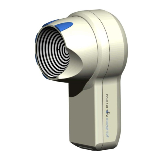
Page 7: Description Of The Unit And Its Functions
The unit is used for measuring corneal topography and has been designed for use in fitting contact The OCULUS Easygraph may be used only with lenses. original parts and accessories delivered by us and in a technically flawless condition. -
Page 8: Before First Use
Page 8 Instruction Manual Easygraph Before First Use Please remove the device as well as the accessories Read these operating instructions carefully. from the packaging and keep this. You can use it for Being an optical device this unit must be handled correctly sending or transporting the device in the with care. -
Page 9: Installation
Page 9 Instruction Manual Easygraph Installation For operation the Easygraph must be fastened with the enclosed holder on a slitlamp. This holder is designed for slitlamps with a drilling of 8mm diameter. It is possible to get other holders on request. -
Page 10: Installation Of Software
PC software. This makes future drivers have to be installed. Initially the Easygraph is firmware-updates more easy, without the necessity registered in the system by „OCULUS – Bootloader“. of the user’s interference. The actual firmware is copied into the Easygraph... -
Page 11: Oculus - Bootloader
6.6.3 OCULUS – Bootloader After having connected the Easygraph correctly to the PC, the operation system shows that a new instrument “OCULUS – Bootloader” has been found and that it is necessary to install a driver: Then click on the button “Continue Anyway”... -
Page 12: Oculus - Easygraph
6.6.4 OCULUS – Easygraph When the Easygraph software is started the first time the operation system shows that a new instrument “OCULUS – Easygraph” has been found and that it is necessary to install a driver: Then click on the button “Continue Anyway”... -
Page 13: Switch Off The Usb-Powersaving
Page 13 Instruction Manual Easygraph 6.6.5 Switch off the USB-Powersaving If Windows is allowed to turn off the device to save Extend the section "Universal Serial Bus controllers" energy, it can cause communication problems. and click with the right mouse button "USB-Root- To prevent this, switch off the USB power Hub"... -
Page 14: Operation
Page 14 Instruction Manual Easygraph Operation Before the Examination Before starting the examination the device must be aligned parallel to the chin support. Always take care in further measurements that the Easygraph is aligned parallel. To achieve high measuring accuracy, a reference measurement must be performed with the Easygraph before the first examination and then around once per month. -
Page 15: After Every Examination
PC and loading the operating pressing any key. system. The OCULUS logo appears. You reach the Patient Data Management To start the examination program, simply select a The following screen display is used for this purpose: patient name or enter a new patient name in the data management system. -
Page 16: Entering A New Patient
Page 16 Instruction Manual Easygraph 7.4.2 Entering a New Patient In order to enter a new patient into the patient data An ID-number of the patient can be entered but is management system, the [Clear] button should be not necessary. activated in order to erase patient data from the If the screen button [File] is now activated, the "Patient"... -
Page 17: Patient Data
Page 17 Instruction Manual Easygraph Activate the screen button [Move Exam.] in the patient data management system window. The patient list then appears. Now the correct patient can be selected in this list (with the scroll bar and by clicking on the correct line). -
Page 18: Importing Patient Data
Page 18 Instruction Manual Easygraph "Data Set" "Memory Available" Use this field to select whether all examinations of The two items of information concerning memory the patient are to be exported or only one. storage space show how much memory space is If only one examination is to be exported, select it in required and how much is available on the storage the Previous Examinations List before activating... -
Page 19: Backup Copies Of Data
Page 19 Instruction Manual Easygraph 7.4.6 Backup Copies of Data 7.4.6.1 Backing Up Data • "Changed and New Data Only" The [Backup] button opens the "Backup" window, which consists of two areas: Only those data are copied which have changed or been newly created since the last backup. -
Page 20: Changing Settings
Page 20 Instruction Manual Easygraph 7.4.7 Changing Settings After the [Settings] screen button has been acti- If you plan to use ID-numbers to call patient data vated, the menu "Change Settings" appears. Here to the screen, the sorting list should be sorted the patient data management system can be accordingly. -
Page 21: The Examination Program
Page 21 Instruction Manual Easygraph The Examination Program • Lens Fitting To start the examination program, first select a patient from the list and confirm this with the Starts a program for fitting contact lenses to the [Easygraph] button (cf. 7.1 page 14). corneal surface which... - Page 22 Page 22 Instruction Manual Easygraph Provided that the Easygraph is nearly in releasing the distance to the patient's eye and shows it position, the Easygraph then automatically measures graphically next to the camera image. This graphical display gives a side view and a top Now the geometric surface of the cornea and the view of the measuring process and also shows the local radii of curvature are calculated from the...
-
Page 23: Using Different Types Of Display To Evaluate Examination
Page 23 Instruction Manual Easygraph 7.5.2 Using Different Types of Display to Evaluate Examination 7.5.2.1 Overview Display • Color Bar Overview Display combines several different evaluation displays and thus provides a quick survey At the right margin of the overview display is a list corneal topography which... - Page 24 Page 24 Instruction Manual Easygraph Ast: Astigmatism in the center of the cornea. • Manual Measuring Function Axs: Axis of the astigmatism Ecc: Mean eccentricity of the cornea This function allows you to measure the distance Øcor: Diameter of cornea (iris) between two arbitrary points in the camera image: Analysed Area.
-
Page 25: Color Map Large
Page 25 Instruction Manual Easygraph 7.5.2.2 Color Map large • Zone diameter: The diameter of the circle (in This form of presentation permits an interactive evaluation of color topographic images. For this mm), on which the measuring point is set. •... - Page 26 Page 26 Instruction Manual Easygraph When the [Tilt] or [Turn] buttons are activated, a The display of the cornea image can also be calculation of the animation process is first carried changed as follows: out, then the image of the cornea is shown in motion. The [Wide Narrow] slide bar adjusts the extent of The display of curvature can be intensified or the movement;...
-
Page 27: Fourier Analysis
Page 27 Instruction Manual Easygraph 7.5.2.4 Fourier Analysis Named after the French physicist Jean Baptiste components are studied in isolation from each other Joseph Fourier (1768-1830), this mathematical in this manner: method permits decomposition of any periodical • function in terms of trigonometric sine and cosine Spherical equivalent functions (Fourier analysis). - Page 28 Page 28 Instruction Manual Easygraph • Combining Fourier components Regular astigmatism One option is to display the “Decentration“ and second-order “Irregularities“ components separately, as described wave represents a above. However, it is also possible to add the regular sine wave of spherical equivalent to each of these components.
-
Page 29: Applications Of The Fourier Display Mode In Keratokonus
Page 29 Instruction Manual Easygraph (Org.) corresponds to the overview display, while the • right color bar has a relative (+/-) scale. At the Spherical RMin: minimal radius of curvature of bottom right of every topographic map is an the spherical component •... - Page 30 Page 30 Instruction Manual Easygraph “Decentration + spher.” “Irregularities”, resp., Irregularities + spherical equivalent” direction decentration is usually In keratoconi of various degrees of severity one often vertical encounters maps with more or less clear-cut three or approximately vertical four-leafed shapes. These are indicative of higher- opposed order corneal aberrations, referred to in the context horizontal...
-
Page 31: Zernike Analysis (Optional)
Page 31 Instruction Manual Easygraph 7.5.2.5 Zernike Analysis (optional) 7.5.2.5.1 General Zernike polynomials are normally used to describe microscope) succeeded in mathematically representing wavefronts. The diagram below shows a parallel the deviations of a real wavefront from an ideal one by wavefront passing through a refractive surface L. - Page 32 Page 32 Instruction Manual Easygraph Overview of the most important Zernike polynomials angular frequency Z 4, ±4 four-lobed defect Z 3,±3 trefoil Z 4, ±2 fourth-order astigmatism Z 2,±2 astigmatism Z 1,±1 tilt Z 3,±1 coma Z 2,0 focus Z 4,0 spherical aberration degree n...
-
Page 33: Zernike Analysis Using The Easygraph
Page 33 Instruction Manual Easygraph 7.5.2.5.2 Zernike Analysis Using the Easygraph The Easygraph performs a Zernike analysis on To start the Zernike analysis select “Zernike measured height data. It calculates for each Zernike analysis” under the menu bar function “Display”. polynomial coefficient which... -
Page 34: Zernike Fit Parameters
Page 34 Instruction Manual Easygraph 7.5.2.5.3 Zernike Fit Parameters There various parameters (“Zernike Parameters”) that may be set before carrying out a Zernike analysis (“Zernike fit“). One of these parameters is the maximum degree (n). This parameter determines many Zernike Click “Calculate new”... -
Page 35: Zernike 2D Display Mode
Page 35 Instruction Manual Easygraph components which may be the cause of impaired reference body: ellipsoid ecc. =0.75 • vision. max. degree: n=8 • ∅max: 8mm constant The function of calculating an aberration coefficient and highlighting abnormal values in red is only These are the parameter settings relevant to the available if the following Zernike fit parameters are normal values. -
Page 36: Indices (Optional)
Page 36 Instruction Manual Easygraph Conventional map based on Zernike 2D map Simulated fluo image sagittal radii 7.5.2.6 Indices (optional) This menu uses the measured surface data to The Easygraph uses the following data for index calculate various indices. Corneal indices permit the calculation: curvature data, height data and Fourier large number of measurement data generated by the analysis as well as Zernike analysis output. - Page 37 Page 37 Instruction Manual Easygraph ISV = Index of Surface Variance. Gives the The instrument compares the measured values with deviation of individual corneal radii from the the mean values and standard deviations of a normal mean value. Elevated in all types of population.
- Page 38 Page 38 Instruction Manual Easygraph A graphic representation of corneal been adapted as far as possible to Amsler’s and eccentricity at 30° for each of the Muckenhirn’s stages. semi-meridians is shown in the middle top right. The axis positions of the central radii are taken into account in this diagram.
-
Page 39: Vertical Decentration
Page 39 Instruction Manual Easygraph 7.5.2.6.1 Vertical Decentration The large map at the top left shows vertical In normal and astigmatic eyes as well as in near- decentration calculated according to a Fourier central keratoconus this display mode yields analysis of height data. Combining the spherical perfectly closed rings. -
Page 40: Refractive Display Mode
Page 40 Instruction Manual Easygraph 7.5.2.7 Refractive Display Mode The refractive display mode permits an assessment In the refractive map (bottom left ) the diopter values of the optical effect of the corneal surface. For this are greater at the periphery because the focal purpose it uses focal distances rather than curvature distance at the periphery (f ) differs from that at... - Page 41 Page 41 Instruction Manual Easygraph Clicking in either of the topographic maps causes the The refraction at the corneal vertex (CVD=0) is curvature value and the refractive value at that point automatically calculated from the spectacle power to be displayed. values and is likewise displayed numerically.
-
Page 42: Height Data
Page 42 Instruction Manual Easygraph 7.5.2.8 Height Data This display mode uses internal three- dimensional height model of the cornea generated Absolute height, P (in a meridian section) is the by the measurement. difference in height between a local point on the corneal surface and a plane which makes contact The use of height data offers the following with the cornea in its center. - Page 43 Page 43 Instruction Manual Easygraph If the “rm” button is active, as in the default setting, “Num” button displays a polar coordinate system the reference body is calculated from the mean showing local height data. This permits central curvature radius and an eccentricity 0.1 assessment of the fit of spheroaspherical or greater than that of the cornea.
- Page 44 Page 44 Instruction Manual Easygraph Applications of the height display method fluo images show that images based on height data The conventional method of imaging keratoconi by yield more accurate results. The conus apex is means of sagittal or tangential radii is prone to always located at the end of the loop-like bulge of artificial distortion.
-
Page 45: Camera Image
Page 45 Instruction Manual Easygraph 7.5.2.9 Camera Image The camera image of the measurement is displayed The magnifying function serves to enlarge details. in original size. This is done by clicking in the image with the left The ring edges determined during image processing mouse button, whereupon the area around the can be sketched in (and deleted again afterward) mouse pointer appears enlarged in the bottom right-... - Page 46 Page 46 Instruction Manual Easygraph This diagram shows the prevailing value of the axis The scale can be changed by clicking with the left position. X-axis: diameter around the apex in mm. Y- mouse button on the color bar. In this way it is axis: diopter value.
-
Page 47: Comparing Examinations
Page 47 Instruction Manual Easygraph 7.5.2.11 Comparing Examinations This type of display makes it possible to compare among the various topographies. This is then different examinations of a patient with each other in displayed in the field at lower left. (For this at least order to evaluate the trend which the cornea is two topographic displays must be loaded.) developing. -
Page 48: Contact Lens Fitting (Optional)
Page 48 Instruction Manual Easygraph 7.5.3 Contact Lens Fitting (optional) The measurement of corneal geometry is of great Contact lens fitting is started by calling the "Lens assistance to the user during contact lens fitting. fitting" (cf. 7.5 page 21) menu to the screen after the Without burdening the patient, it permits the insertion examination. -
Page 49: Selecting A Contact Lens
Page 49 Instruction Manual Easygraph 7.5.3.1 Selecting a Contact Lens The geometric data of the cornea serve to calculate suggestions for all available contact lens types; these are then entered into the list of suggestions. The list at the very top specifies contact lens geometries which most closely correspond to the measured cornea. -
Page 50: Fluo Image Simulation / [Calc. Fluo.]
Page 50 Instruction Manual Easygraph 7.5.3.2 Fluo Image Simulation / [Calc. fluo.] Activating the [Calc. fluo.] key causes a fluo image After the first fluo image simulation a field titled “CL simulation to be carried out. Here the following power” appears at the bottom right. Here the power parameters are calculated: values of the contact lens can be calculated as a function of the patient’s spectacle power and the... -
Page 51: Fluo Icon Selection Switches
Page 51 Instruction Manual Easygraph 7.5.3.2.1 Fluo Icon Selection Switches Every new fluo image generates a selection button in the form of a miniaturized fluo image. These fluo icons are listed in the right margin of the main fluo image. Clicking on one of these fluo icons with the left mouse button causes the corresponding fluo image to be reloaded along with the calculated diagrams... -
Page 52: Setting Contact Lens Parameters / [Details]
Page 52 Instruction Manual Easygraph The position of the contact lens is shown in the Definition of inclination angle “Position” field: -90° R/L: positive stands for right, negative for left, The inclination angle is U/D: positive for up and negative for down, the angle between the Incl.: inclination angle of the contact lens. -
Page 53: Changing The Scale Of The Fluo Image
Page 53 Instruction Manual Easygraph 7.5.3.2.4 Changing the Scale of the Fluo Image To change the scale of the fluo image, click on the Changing the scale can be helpful in cases of, for green color bar in the left margin of the fluo image. example, marked keratoconus, as a larger maximum value (e.g. -
Page 54: Using Hecht Fitting Software / [Hecht Cl]
Hecht software deactivates the relevant input fields in the OCULUS software. This is to ensure that a contact lens in the Hecht software can be altered by none other than the Hecht software. The input fields are reactivated as soon as you enter a new contact lens suggestion or select a different manufacturer. -
Page 55: Refraction Module / [Refraction]
Page 55 Instruction Manual Easygraph 7.5.3.3 Refraction Module / [Refraction] The refraction module permits a calculation of the vertex distance (CVD) and displayed in the column required refraction of the contact lens as a function of “CVD=0”. spectacle power and lens type. It also enables you to If power values have already been entered, these will compare different lens types (e.g. -
Page 56: Power Calculation For Toric Lenses
Page 56 Instruction Manual Easygraph • Cornea The Refraction Module contains the following fields: This field displays the keratometric values of the • Spectacle power cornea measured by means of the Easygraph: Entry of power values and automatic calculation of corneal vertex refraction (CVD=0). - Page 57 Page 57 Instruction Manual Easygraph Note ⇒ The refractive index always has to be compensated by a cylindrical component in the anterior surface. With the induced astigmatism entered manually (i.e. in the case of toric lenses). It is neutralized by the shape of its anterior surface, not stored along with the other contact lens this type of contact lens corrects corneal parameters in the contact lens database.
-
Page 58: Power Calculation For Soft Lenses
Page 58 Instruction Manual Easygraph 7.5.3.3.2 Power Calculation for Soft Lenses Calculating contact lens power is simpler in the case rounded result to the “Test lens soft” field. The of soft lenses because of the absence of a tear lens. expected remaining power for this contact lens is Here the power calculation module first calculates calculated using the axis position of the patient’s... - Page 59 Page 59 Instruction Manual Easygraph Loading fitted contact lenses: The fluo image is not stored along with the other data Stored refraction contact lens data and should therefore first be calculated by clicking automatically loaded together with the examination the [Calc. fluo.] button and assessed. The refraction data (cf.
-
Page 60: Changing Settings
Page 60 Instruction Manual Easygraph 7.5.4 Changing Settings The examination program allows the user to adapt The relative color scales can be displayed in working procedures to his own preferences. This is three different increments (cf. table below). carried out in the "Change Settings" menu. Relative Unit of Curvature The following points can be adjusted:... - Page 61 (not measured parts are white). • Color table In addition to the “Internal” color table used by OCULUS you can also use an “External” color table. This enables you to adapt colors to other topographs better comparison examinations.
- Page 62 Page 62 Instruction Manual Easygraph • Language: • Communication The language which the program uses for output The type of interface can be chosen between can be selected from among German, English, serial USB. Presently Easygraph French and Italian. supports the USB interface only. With the switch [System->] the details of the chosen type of •...
-
Page 63: Change System Settings" Button [System->]
Page 63 Instruction Manual Easygraph 7.5.4.1 “Change System Settings” Button [System->] • Mode Here you can set the communication mode and the interface. The Easygraph only responds if the “Online” mode has been selected. Setting the mode to “Demo mode” permits you to use the software without the Easygraph. - Page 64 Page 64 Instruction Manual Easygraph 7.5.4.2 Contact Lens Database The Easygraph has a contact lens database Activating or deactivating a manufacturer in the left containing posterior surface geometries for contact box removes or adds that manufacturer's name in the lens fitting. right-hand box.
-
Page 65: Input New Contact Lens Types / [Lens Geometry ->]
Page 65 Instruction Manual Easygraph 7.5.4.3 Input New Contact Lens Types / [Lens geometry ->] This window is used to display and add to the The corresponding abbreviations must also be geometries of contact lenses which have already entered. been stored. Abbreviations used list... -
Page 66: Creating Contact Lens Geometries (Rigid)
Page 66 Instruction Manual Easygraph Two programs are available for creating serial The [Save + Quit] button stores changes made and contact lens data. returns to the "Confirm Contact Lens" display. The [Add lenses] button is used to create rigid lens The [Cancel] button rejects all changes and likewise geometries (cf. - Page 67 Page 67 Instruction Manual Easygraph 2. The Periphery The periphery of contact lenses must also be clicking the "r1 = constant" or "r2 = constant" entered after the base parameters have been buttons. defined. Two peripheral zones, each with 3 If the curvature of the zones is not constant but parameters, can be entered: depends on the central radius, it can be defined by...
-
Page 68: Creating Soft Lens Geometries
Page 68 Instruction Manual Easygraph • Example: 3-curve lens b1 = constant b1=0.40 r1=r0*A+B A=1.20 B=0.00 dr1 = constant dr1=0 b2 = constant b2=0.40 r2=r0*A+B A=1.50 B=0.00 dr2 = constant dr2=0 • Example: Toric lens with bevel b1 = constant b1=0.25 r1=r0*A+B A=1.50... -
Page 69: Import And Export Of Contact Lens Data
Page 69 Instruction Manual Easygraph 7.5.4.3.3 Import and Export of Contact Lens Data The following display appears after a diskette has the "Choose Contact Lens" menu (cf. 7.5.4.2 page been inserted and the [Import / Export ->] button in 64) has been clicked: Two lists are now displayed: The following answers are possible: The list at the left shows contact lens types which are... -
Page 70: Other Functions Of The Examination Program
Page 70 Instruction Manual Easygraph [All] Mark all contact lens types in Changes on the diskette are always carried out the list. immediately. [Compare] Compare both lists mark However, changes in the PC database become only those contact lens types effective only after the [Save + Quit] button is which are still missing. -
Page 71: Printout
Page 71 Instruction Manual Easygraph 7.5.5.2 Printout The "Print" menu function permits the screen If the “Print” switch is set to “B/W“ (see 7.5.4, page contents of the moment to be printed out at the 62), the otherwise gray screen background appears printer, so that any displays which are available for white;... -
Page 72: Maintenance
Page 72 Instruction Manual Easygraph Maintenance Care and Cleaning Always disconnect the main plug before cleaning the unit! The Housing Ring calotte Do not use aggressive cleaners containing chlorine, The ring calotte is a precision-made part and should solvents, abrasives, or powerful chemicals! not be subjected to pressure. -
Page 73: Terms Of Warranty And Service
No liability changes made in the ratings or the capacities of the whatever is possible on the part of OCULUS if unit if required. The certification must bear the date assembly work, additions to the unit, readjustments,... -
Page 74: Disposal
Page 74 Instruction Manual Easygraph Disposal Have the packaging disposed of as Batteries should be disposed of as special waste. recyclable waste. Materials should be disposed of according to the When the device has reached the laws of your country. end of its service life it has to be Please use the services of suitable waste disposal disposed of properly:... -
Page 75: Literature
VideoEasygraphic Data, 15: 171-185, Hjortdal Verwendbarkeit des Oculus Easygraphen für die JØ/Erdmann L/Bek T praktische Contactlinsenanpassung" 25. DOZ. 1997, 52(4): 92-96 (Part 1) und 52(5): 104- 11. NOJ 6/1998; "Die Verwendbarkeit des Oculus 107 (Part 2), Cornea: Abbildungseigenschaften Easygraphen für praktische Topometrie, Löffler... -
Page 76: Index
Page 76 Instruction Manual Easygraph Index Contact Lens, Rotating ..........51 Contact Lens, Shifting..........51 Contact Lens, Soft ...........49 AA ................37 Contact Lens, Toric..........49, 57 aberration..............31 ABR................37 cornea, diameter ..........24, 41 corneal vertex distance ..........41 Absolute Color Scale ..........60 Add new Contact Lens Type........65 Corneal Vertex Distance..........55 Corneal Vertex Power..........55 Amsler’s stages............38... - Page 77 Page 77 Instruction Manual Easygraph Fluo Icon ..............51 Measurement, Force..........22 Fluo Icon, Delete............51 Measurement, Release..........22 Fluo Image Simulation ..........50 Millimeter..............60 Fluo Image, Scale of..........53 Minimum PC requirements ........74 focal distances ............40 Move Examination ...........17 Force Measurement..........22 Fourier analysis............27 Fourier indices ............28 n, Refraction Index...........56 Name, Rename............17 New Measurement...........21...
- Page 78 Page 78 Instruction Manual Easygraph Release (default)............62 Releasing Measurement..........22 Tangential Curvature ..........62 Remaining Power, Expected ........55 Technical Data ............74 Rename Patient ............17 Time, actual .............20 Restore ..............19 Top Test..............53 retinoscopy...............38 Toric Contact Lens...........57 Ring Edges ..............45 Toric Contact Lenses ..........49 RMin..............29, 37 Transport and Storage..........7 Rotatable reflector .............8...
- Page 79 Guidelines and manufacturer's declaration regarding electromagnetic interference immunity ELEKTROMAGNETIC EMISSIONS: DIN EN 60601-1-2, 6.8.3.201, Table 201 The Oculus Devices are designed for use in the electromagnetic environment described below. The user of Oculus Devices is to ensure that it is used in such an environment.
- Page 80 τ τ Voltage dips, brief power or hospital environment. periods periods outages and fluctuations in If the user of Oculus equipment requires power supply voltage acc. to continuous operation even in the event of 70% U 70% U τ τ...
- Page 81 ELEKTROMAGNETIC INTERFERENCE IMMUNITY DIN EN 60601-1-2, 6.8.3.201, Table 204 Interference Level of Immunity IEC 60601 Test Level Electromagnetic Environment Guidelines Compatibility Tests Portable and mobile radio equipment should not be placed closer to the equipment and its electric wiring than the recommended distance derived from the equation which is applicable for the transmission frequency.
- Page 82 RECOMMENDED SAFETY DISTANCES BETWEEN PORTABLE AND MOBILE HF TELECOMMUNIKATION EQUIPMENT AND OCULUS DEVICES DIN EN 60601-1-2, 6.8.3.201, Table 206 This unit is designed for use in an electromagnetic environment in which HF disturbances have been minimized. The user of the unit can help to avoid electromagnetic disturbances by ensuring that minimum distances are maintained between portable and mobile HF telecommunication equipment (i.e.
- Page 83 OCULUS OCULUS Optikgeräte GmbH Münchholzhäuser Str.29 KONFORMITÄTSERKLÄRUNG / D-35582 Wetzlar DECLARATION DE CONFORMITE / Tel: ++49 641 / 20 05 – 0 Fax: ++49 641 / 20 05 - 255 DECLARATION OF CONFORMITY / DICLARATIONE DE CONFORMITA / DECLARATION DE CONFORMITA OCULUS Optikgeräte GmbH...
Need help?
Do you have a question about the Easygraph 70620 and is the answer not in the manual?
Questions and answers