Table of Contents
Advertisement
Quick Links
Advertisement
Table of Contents

Related Manuals for OCULUS Myopia Master


Summary of Contents for OCULUS Myopia Master
- Page 1 ® ® OCULUS Myopia Master INSTRUCTION MANUAL...
- Page 3 Notes on this instruction manual The Myopia Master® has been manufactured and tested according to strict quality criteria. To ensure safe operation, it is essential that you use the device correctly. For this reason you should familiarise yourself thoroughly with the contents of this instruction manual before operating the device.
-
Page 4: Table Of Contents
Intended Use..........................13 Transport to Installation Location..................14 Device Description ........................15 Overview of Device Components ................15 Mode of Operation of the Myopia Master®............17 Set up and Connection......................19 Initial Start-up ......................19 Set-up Jobs for Initial Start-Up ................19 Adjustments after an in-house transport............. - Page 5 22 Annex ............................72 22.1 Electromagnetic Compatibility ................72 22.2 Guidance and Manufacturer’s Declaration - Electromagnetic Emissions and Immunity for the Myopia Master® ..........74 22.3 Description of the Connection .................78 22.4 Data Sheet GSM60B15-P1J (05150725) ..............79 22.5 Notes for integration into an IT-Network ............82 iii / iii Instruction Manual Myopia Master®...
-
Page 6: Scope Of Delivery
Myopia Master® Basic without chin and head rest 68130 incl. auto-refractometer, keratometry, axial length Myopia Master Optiswiss with chin and head rest (only available via 10010728 Optiswiss AG) incl. auto-refractometer, keratometry, axial length Eye shield black 076500001028 Dust protection cover... -
Page 7: Graphic Symbols
Applied part Type B Do not re-use Limit of humidity Medical device Limit of air pressure Example: UDI number, consisting UDI- DI (Device-Identification) UDI-PI (Product Identifier) machine-readable matrix code 2 / 84 Instruction Manual Myopia Master® (G/68100/EN Rev08) - Page 8 Conform to US and Nemkos symbol Chinese Standard Canadian standards Sign Meets German Polarity of safety requirements DC connector Fig. 2-1: Name plate (example) There are no temporarily fixed markings on the device. Instruction Manual Myopia Master® (G/68100/EN Rev08) 3 / 84...
-
Page 9: Structure Of The Documentation
Myopia Master®. Attention All safety-related instructions for use of the Myopia Master® are given in the Instruction Manual for the unit. It is imperative that you read and understand the whole Instruction Manual before you use the Myopia Master®. -
Page 10: Safety Instructions
Identifies important information about the product and its use which require special attention. > This symbol denotes menu paths and screenshots. Example for starting a new examination: Myopia Master® > Examination > Scan which means: Select the “Examination” menu from the menu bar. ... -
Page 11: Safety Instructions For Use
Only OCULUS or an authorized dealer is allowed to set up and to connect the Myopia Master®. Do not use or store the Myopia Master® in rooms that are humid, see sec. 18, page Keep the Myopia Master® away from water that may drip, splash or spray on it, and make sure that no liquids can get into the Myopia Master®. - Page 12 4 Safety Instructions Set up the Myopia Master® so that the power plug is easy to access. That way, you can easily disconnect it from the power supply for any repairs or maintenance work. Do not force any plug connections.
- Page 13 Make sure that all devices of the ME system meet the requirements of IEC 60601-1 or IEC 60950-1/IEC 62368-1. Instructions for Operation Before first use: Let OCULUS or an authorized dealer train you in the operation of the Myopia Master®. Never operate a damaged Myopia Master®.
- Page 14 Myopia Master®. If an error occurs which you cannot correct, label the Myopia Master® as being “out-of-order” and contact our service department, see sec.
-
Page 15: Cybersecurity Instructions
4 Safety Instructions If you are using a new computer for the Myopia Master®, you must have the electrical safety checked. Call OCULUS Service for this purpose. Attention Electromagnetic Compatibility (EMC) / Cables Risk of personal injury or damage to property due to electromagnetic... - Page 16 Lock the computer if you are leaving the workstation (shortcut: ‘windows logo key’ + ‘L’). Instruction Manual Myopia Master® (G/68100/EN Rev08) 11 / 84...
- Page 17 Heed the instructions for integration into an IT-Network sec. 22.5, page 82 Do not use the Myopia Master® with wireless technology, for example (connection between device and computer) with wireless USB 12 / 84 Instruction Manual Myopia Master® (G/68100/EN Rev08)
-
Page 18: Intended Use
The integrated ophthalmic refractometer measures the refractive power of the eye. The integrated interferometer measures the axial length of the eye. The Myopia Master® may only be used for the purpose described in this instruction manual. Heed the safety instructions listed above. -
Page 19: Transport To Installation Location
Avoid contamination, high temperatures and humidity. Transport the Myopia Master® professionally. Store the Myopia Master® according to the storage conditions. Avoid placing near radiators and moisture. Note Keep the packing material. You can then ship or transport the unit in the proper manner for any servicing or repairs that may arise. -
Page 20: Device Description
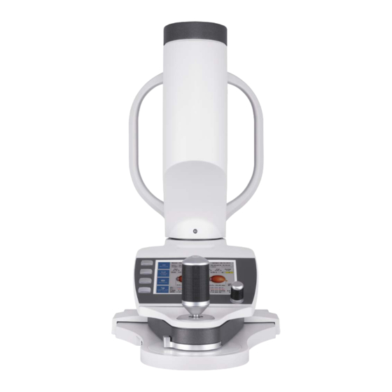
7 Device Description Device Description Overview of Device Components Gauge head Control Wheel Function keys Printout slot Sliding plate Display Joystick Fig. 7-1: Device components Instruction Manual Myopia Master® (G/68100/EN Rev08) 15 / 84... - Page 21 7 Device Description Head rest Control LED Chin rest Marking for the eye height Mains connection Measuring ocular / Patient eyepiece with Keratometer ring On/Off Switch USB port Fig. 7-2: Device components 16 / 84 Instruction Manual Myopia Master® (G/68100/EN Rev08)
-
Page 22: Mode Of Operation Of The Myopia Master
Due to this arrangement, sharp sectional images of the cornea can be attained. Axial length The axial length of the eye is measured and displayed by interferometry. The Myopia Master® measures six times the axial length of the patient‘s eye. Instruction Manual Myopia Master® (G/68100/EN Rev08) 17 / 84... - Page 23 7 Device Description Applied parts 1 Head rest 2 Chin rest Fig. 7-3: Applied parts 18 / 84 Instruction Manual Myopia Master® (G/68100/EN Rev08)
-
Page 24: Set Up And Connection
8 Set up and Connection Set up and Connection Initial Start-up Before you can operate the Myopia Master® for the first time, you must set it up and adjust it get trained Attention Incorrect measurements / equipment damage due to a lack training ... -
Page 25: Adjustments After An In-House Transport
Adjustments after an in-house transport Note Equipment damage due to incorrect lifting If the Myopia Master® is lifted only by the measure head, it can break off. Grab the Myopia Master® from below and the head rest to lift it. - Page 26 Press down gently on the transportation safety device and turn it counter-clockwise to the “unlocked” position (2). The spring will push the transport safety device up. Close the cover with the display, fig. 8-1, page Instruction Manual Myopia Master® (G/68100/EN Rev08) 21 / 84...
-
Page 27: Electrical Connection
Do not use the Myopia Master® adjacent to or stacked with other equipment. If you have to use the Myopia Master® adjacent to or stacked with other equipment, verify the correct operation of the Myopia Master®. Only use the power adapter listed in the list, sec. - Page 28 8 Set up and Connection Note Risk of equipment damage due to incorrect connection If you do not connect the Myopia Master® properly, and the connection is live, the unit can be damaged within a short period of time. ...
-
Page 29: Operation
Master® for the first time. Extreme temperature changes from cold areas to warm rooms can cause condensation on the optical components. Switching On Turn on the Myopia Master® with the On/Off Switch (position I). The LED lights up green. Switching Off End the current session. -
Page 30: Functions Of The Control Pad
Lightly press on the desired button acts as a touch screen Compound slide (5) Used for rough adjustment Move the adjusting base until you can see the patient’s eye clearly on the screen. Instruction Manual Myopia Master® (G/68100/EN Rev08) 25 / 84... -
Page 31: Touch Screen
Function Keys on the Touch Screen Use these function keys to work with the patient data management system. Button Function Button Function Change keyboard Enter Delete character Return to upper line Escape 26 / 84 Instruction Manual Myopia Master® (G/68100/EN Rev08) -
Page 32: Preparing Patients Data
In the “D. o. Birth” field, the keyboard changes to a numeric keypad. Enter the date of birth and confirm. A confirmation dialog box appears. Select the option “Yes”. Instruction Manual Myopia Master® (G/68100/EN Rev08) 27 / 84... - Page 33 11 Preparing Patients Data The name of the patient appears in the list. Fig. 11-2: Patient list Press the [Measure] button to switch to measuring mode. 28 / 84 Instruction Manual Myopia Master® (G/68100/EN Rev08)
-
Page 34: Entering New Patients (Touch Screen Deactivated)
You will now be asked whether you want to save the new patient data. Select the option “Yes”. The name of the patient appears in the list. Press the [Measure] button to switch to measuring mode. Instruction Manual Myopia Master® (G/68100/EN Rev08) 29 / 84... -
Page 35: Selecting Existing Patients
Select the patient that you want to rename. Press the button. Enter the new name in the field “New Name”, or enter a new date of birth. Confirm your input. 30 / 84 Instruction Manual Myopia Master® (G/68100/EN Rev08) -
Page 36: Delete A Patient Or An Examination
Select with the control wheel the button [Examination]. Select the examination that is to be deleted. The line for the selected examination appears highlighted in blue. Press the control wheel. The examination is deleted. Instruction Manual Myopia Master® (G/68100/EN Rev08) 31 / 84... -
Page 37: Load An Examination
(right, left). The measurements must then be loaded separately, one after the other. Generally, two measurements can only be displayed together when they belong to a single measuring operation. 32 / 84 Instruction Manual Myopia Master® (G/68100/EN Rev08) -
Page 38: Measuring Procedure
Measuring Procedure Caution Risk of incorrect measurement due to incorrect use Before first use: Let OCULUS or an authorized dealer train you in the operation of the Myopia Master®. A measuring procedure consists of the following steps: Selecting a measuring mode ... -
Page 39: Preparing A Measurement
Turn it clockwise to move the gauge head upwards. Turn it counter-clockwise to move it downwards. 1. If you turn the joystick to the limit stop, the measuring head and the chin rest move in the opposite direction. 34 / 84 Instruction Manual Myopia Master® (G/68100/EN Rev08) - Page 40 When the position has been reached accurately enough, a cross appears in the center of the ring that is bordered by four bars. The Myopia Master® will automatically begin measuring. Alternately you can start the measuring procedure manually. Manual measurement: ...
- Page 41 The respective measurement can be found in the memory. Select the appropriate eye to load the examination that was just conducted. To delete the existing examinations from the memory, press this button. 36 / 84 Instruction Manual Myopia Master® (G/68100/EN Rev08)
-
Page 42: Myopia Measurement And Results
The measured values of the myopia examination are displayed in the overview display. 1 Patient and examination data 3 AXL images 2 Refraction values 4 Keratometry values Fig. 12-5: Myopia overview display Instruction Manual Myopia Master® (G/68100/EN Rev08) 37 / 84... -
Page 43: Myopia Results
Growth curves If the “Growth curves” display is selected, the graphic shows the measured axial length values depending on the age of the patient. The grey lines reflect the percentile curves. 38 / 84 Instruction Manual Myopia Master® (G/68100/EN Rev08) - Page 44 Axial length (without percentile curves) Regardless of the display selected, you can manually set the risk of myopia using the colour bar (4). Press the button to change to the risk factors display. Instruction Manual Myopia Master® (G/68100/EN Rev08) 39 / 84...
- Page 45 You can therefore use the control wheel and confirm by pushing. Alternatively use the arrow button to the right for increasing or to the left for decreasing the values. Press the button to change to the AR + K display. 40 / 84 Instruction Manual Myopia Master® (G/68100/EN Rev08)
-
Page 46: Refraction Results
Astig: Astigmatism of cornea in the center WTW: (white-to-white) Cornea diameter or iris diameter. Q-value: If the field has a white background (9-7) - the measuring results are good. Instruction Manual Myopia Master® (G/68100/EN Rev08) 41 / 84... -
Page 47: Axial Length Results
The corresponding signal to noise ration (SNR) (3) is listed. A specially averaged axial length and the highest SNR (4) are displayed. Furthermore the SNR is shown in a graph (5). 42 / 84 Instruction Manual Myopia Master® (G/68100/EN Rev08) -
Page 48: Pachymetry Results (Optional)
You can move the pointer to the left or to the right on the touch screen with the rotary knob. 12.3.6 Ending the measurements Print and/or save the data, sec. 12.4, page Instruction Manual Myopia Master® (G/68100/EN Rev08) 43 / 84... -
Page 49: Printing And Saving Examinations
“Chronology of Different Measuring Processes” (sec. 13, page 46). Save the examination retroactively if you did not set up a new patient (sec. 13.2, page 47) prior to executing the measuring process. 44 / 84 Instruction Manual Myopia Master® (G/68100/EN Rev08) -
Page 50: Saving An Examination
After each patient remove one of the paper sheets from the chin rest. See also sec. 16.4, page Disinfect the head rest and, if necessary, the chin rest after each patient, sec. 16.2, page Instruction Manual Myopia Master® (G/68100/EN Rev08) 45 / 84... -
Page 51: Chronology Of Different Measuring Processes
(fig. 12-5, page 37). The conducted examinations are automatically saved in the patient data management. The saved examinations can be viewed again at any time (sec. 12.4, page 44). 46 / 84 Instruction Manual Myopia Master® (G/68100/EN Rev08) -
Page 52: Saving An Examination Retroactively
When the measuring operation has been completed, the overview screen appears (fig. 12-5, page 37). In the overview screen, press the button [Save to Patient]. The “Patient List” display opens. Fig. 13-2: Patient list Instruction Manual Myopia Master® (G/68100/EN Rev08) 47 / 84... -
Page 53: Measuring Without Saving The Patient Data
37). Print out the measurement(s) (sec. 12.4, page 44). When printed out, each measurement is automatically temporarily saved to the exam nr. memory (“Saving data by Exam no. memory”, page 45). 48 / 84 Instruction Manual Myopia Master® (G/68100/EN Rev08) -
Page 54: Reference Measurement
14 Reference Measurement Reference Measurement To achieve a high measuring accuracy, the Myopia Master® must be set before conducting the first examination on a patient after changing the position of the Myopia Master® The first reference measurement is performed during setup by OCULUS or an authorized dealer. - Page 55 14 Reference Measurement Fig. 14-2: Example: Result on reference tool The system is now ready for operation. 50 / 84 Instruction Manual Myopia Master® (G/68100/EN Rev08)
-
Page 56: Settings
“Detail” mode additionally displays the values of the individual measuring steps. Cyl mode Select whether plus or minus cylinders are to be used. When the program is started, this preselected cylinder type is then always active. Instruction Manual Myopia Master® (G/68100/EN Rev08) 51 / 84... - Page 57 You can deactivate the checkbox e.g. for data protection reasons, then the patient list is empty. Fig. 15-2: Empty patient list when checkbox is deactivated 52 / 84 Instruction Manual Myopia Master® (G/68100/EN Rev08)
-
Page 58: Settings 2
Language Select the on-screen language. Interface You can deactivate the interfaces. If the Myopia Master® is connected to a computer via USB, you need to set the interface settings to “USB”. Instruction Manual Myopia Master® (G/68100/EN Rev08) 53 / 84... - Page 59 If the checkbox is activated, then a “peep tone” will sound- when the touch screen is operated. Exam.Nr. The “Exam Nr.” that appears on every printout for identifications purposes can be reset to zero at any time. 54 / 84 Instruction Manual Myopia Master® (G/68100/EN Rev08)
-
Page 60: Settings 3
In “Settings 3” the display of growth curves can be activated in the lower area “Licensing options” using the device license “Growth Curve”. Contact your OCULUS contact person to acquire a corresponding licence. To activate the growth curves, enter the release ID in the field provided. -
Page 61: Settings 4
On the “Settings 4” screen, you can individually configure the printout. Print AR Details Print AR Details: activated Print AR Details: deactivated Print Keratometer Details Print Kera Details: activated Print Kera Details: deactivated 56 / 84 Instruction Manual Myopia Master® (G/68100/EN Rev08) - Page 62 Enter the appropriate information in the lines provided for that purpose and activate the checkboxes in front of each line. OD/OS According to the settings R (right) and L (left) is printed out or OD (oculus dexter) and OS (oculus sinister). Instruction Manual Myopia Master® (G/68100/EN Rev08)
- Page 63 15 Settings 15.5 Settings 5 Fig. 15-7: Settings 5 58 / 84 Instruction Manual Myopia Master® (G/68100/EN Rev08)
-
Page 64: Cleaning, Disinfection And Maintenance
Note Equipment damage due to moisture Make sure that no liquid can get into the Myopia Master®. 16.1 Cleaning Caution Risk of electric shock if the Myopia Master® is not completely disconnected from the mains for the cleaning. - Page 65 2 Protective glass covers Fig. 16-1: Cleaning Cleaning head rest and chin rests The Myopia Master® can be switched on for cleaning the head rest and chin rest. During the measuring process, sweat, cosmetics, etc. from the patient can get on the head and chin rest.
-
Page 66: Disinfection
Clean the touch screen using a dry, lint-free cloth. 16.2 Disinfection Caution Risk of electric shock if the Myopia Master® is not completely disconnected from the mains for the disinfection. Turn the Myopia Master® off, sec. 9.2, page ... -
Page 67: Maintenance
Spray the disinfectant solution onto a cleaning cloth, do not spray it directly on the device. 16.3 Maintenance The Myopia Master® is designed so that no special maintenance is necessary. For safety reasons, we recommend that the illumination and electrical values be checked every two years. ... -
Page 68: Attaching Paper To The Chin Rest
Caution Risk of personal injury or material damage due to invisible laser radiation The Myopia Master® contains a Class 1 laser according to IEC 60825- 1:2015 and IEC 60825-1: 2001. It is an encapsulated laser system. When the Myopia Master® cover is opened, you may be exposed to invisible, Class 3R (5 mW) laser radiation. -
Page 69: Inserting A New Roll Of Printer Paper
Proper paper guide Wrong paper guide Fig. 16-4: Inserting the paper Press the button “Printer Feed” so that the printer paper is pulled through the opening. Close the opened display unit. 64 / 84 Instruction Manual Myopia Master® (G/68100/EN Rev08) -
Page 70: Troubleshooting
Risk of personal injury or equipment damage due to improper troubleshooting Do not plug in or pull out any cables while the Myopia Master® is switched on. If an error occurs which you are unable to correct by following the instructions below, label the device as “out-of-order”... -
Page 71: Dismantling, Transport And Storage
18 Dismantling, Transport and Storage Dismantling, Transport and Storage The Myopia Master®, must be properly dismantled and packed before being transported or stored. 18.1 Disassembly End the current session. Switch off the Myopia Master® with the On/Off Switch. -
Page 72: Disposal
In accordance with legal regulations, you are entitled to a warranty for the Myopia Master®. If modifications are made to the Myopia Master® by unauthorized persons, all warranty claims shall be voided. Improper modifications and repairs may result in considerable hazards to users and patients. -
Page 73: Assumption Of Liability For Functions And Damage
20.2 Assumption of Liability for Functions and Damage OCULUS will only accept responsibility for the safety, reliability and serviceability of the Myopia Master® if the unit is used in compliance with the following terms: Only use the equipment in conformance with this instruction manual. -
Page 74: Technical Data
Cylinder 10 D (VD = 12 mm) (increments: 0,01; 0,12; 0,25 D) Axis 1 — 180° (increments: 1°) Minimum pupil diameter 2.5 mm Axial length Axial length 14 — 40 mm Instruction Manual Myopia Master® (G/68100/EN Rev08) 69 / 84... - Page 75 Power adapter Power adapter GSM60B15-P1J (05150725) AC input 80 — 264 V AC Frequency 47 — 63 Hz DC output 15 V DC/4 A, 60 W max. Fuses Integrated overcurrent shut-off 70 / 84 Instruction Manual Myopia Master® (G/68100/EN Rev08)
- Page 76 DIN EN 60825-1:2015 and DIN EN 60825-1: 2001 The unit contains a Class 1 laser. Maximum output of the laser radiation 0.7 mW Single pulse duration 510 – 760 ms Pulse count per examination Wavelength 880 nm Instruction Manual Myopia Master® (G/68100/EN Rev08) 71 / 84...
-
Page 77: Annex
EMC, and must be installed and operated according to the EMC-Instructions contained in the accompanying paperwork. No special measures need be observed in respect of OCULUS devices and systems. Portable and mobile RF-communications devices can interfere with electrically operated medical devices. - Page 78 Cable, USA (optional) 1.8 m 5200920 Cable, AU (optional) 1.8 m 5200925 Cable, Argentinia (optional) 1.8 m 05150725 Power adapter GSM60B15-P1J 015692000010 USB FS MED-Isolator 05200600 USB mini cable (39.4 in) Instruction Manual Myopia Master® (G/68100/EN Rev08) 73 / 84...
-
Page 79: Guidance And Manufacturer's Declaration - Electromagnetic Emissions And Immunity For The Myopia Master
IEC 60601-1-2: 2015, based to table 1 The OCULUS Myopia Master® is intended for operation in the electromagnetic environment specified below. The user of the Myopia Master® should ensure that it is being used in such an environment. Emissions test... - Page 80 0 degree 0 degree 0% U ; 250/300 0% U ; 250/300 τ τ periods periods Note: U is the a.c. mains voltage prior to application of the test level τ Instruction Manual Myopia Master® (G/68100/EN Rev08) 75 / 84...
- Page 81 To assess the electromagnetic environment due to fixed RF transmitters, and electromagnetic site survey should be considered. If the measured field strength in the location in which the Myopia Master® is used exceeds the applicable RF compliance level above, the Myopia Master® should be observed to verify normal operation.
- Page 82 RF communications equipment and the Myopia Master®, IEC 60601-1-2:2015, table 6 The Myopia Master® in intended for use in an electromagnetic environment in which radiated RF disturbances are controlled. The customer or the user of the Myopia Master® can help prevent electromagnetic interference by maintaining a minimum distance between portable and mobile RF communications equipment (transmitters) and the Myopia Master®...
-
Page 83: Description Of The Connection
22 Annex 22.3 Description of the Connection ® Myopia Master Power supply adapter USB-mini cable (05150725) 05200600 USB isolator Computer/PC/Laptop Mains connection 78 / 84 Instruction Manual Myopia Master® (G/68100/EN Rev08) -
Page 84: Data Sheet Gsm60B15-P1J (05150725)
22 Annex 22.4 Data Sheet GSM60B15-P1J (05150725) Instruction Manual Myopia Master® (G/68100/EN Rev08) 79 / 84... - Page 85 22 Annex 80 / 84 Instruction Manual Myopia Master® (G/68100/EN Rev08)
- Page 86 22 Annex Instruction Manual Myopia Master® (G/68100/EN Rev08) 81 / 84...
-
Page 87: Notes For Integration Into An It-Network
PEMS into to meet the IT-Network: Loss of data unsuitable data exchange Data corruption unsuitable temporal data allocation 82 / 84 Instruction Manual Myopia Master® (G/68100/EN Rev08) - Page 88 Changes to the IT-Network include: changes in IT-Network configuration connection of additional items to the IT-Network disconnecting items from the IT-Network update of equipment connected to the IT-Network Instruction Manual Myopia Master® (G/68100/EN Rev08) 83 / 84...
- Page 89 22 Annex 84 / 84 Instruction Manual Myopia Master® (G/68100/EN Rev08)
- Page 90 Manufacturer and Service Address Headquarters: OCULUS Optikgeräte GmbH Münchholzhäuser Straße 29 • 35582 Wetzlar • GERMANY Tel. +49 641 2005-0 • Fax +49 641 2005-255 E-Mail: sales@oculus.de • www.oculus.de USA: OCULUS, Inc. 17721 59th Avenue NE • Arlington • WA 98223 Tel.
Need help?
Do you have a question about the Myopia Master and is the answer not in the manual?
Questions and answers