Table of Contents
Advertisement
Quick Links
Advertisement
Table of Contents

Related Manuals for OCULUS Corvis ST


Summary of Contents for OCULUS Corvis ST
- Page 1 ® OCULUS Corvis INSTRUCTION MANUAL Tonometer - Pachymeter...
- Page 2 Notes on this instruction manual Thank you for your purchase and the trust you have placed in this OCULUS product. The Corvis® ST has been manufactured and tested according to strict quality criteria. You have selected a modern and well-engineered product.
-
Page 3: Table Of Contents
Table of Contents Table of Contents Scope of Delivery.........................1 Symbols ............................2 Structure of the Documentation ....................3 Safety Instructions........................4 About this Manual ......................4 4.1.1 Graphic symbols used..................4 Safety Instructions for Use ..................5 Indications for Use........................11 Contraindications........................11 Warnings ............................ 11 Transport to Installation Location.................. - Page 4 Table of Contents 12.4 Perform a second measurement................37 12.5 Saving data........................38 12.6 Complete measurement .....................39 12.7 Using Patient Data Management................40 12.7.1 Rename Patient Data ................40 12.7.2 Exporting Patient Data ................40 12.7.3 Data backup....................41 12.7.4 Backup data....................42 12.7.5 Reconstruct data ..................42 12.7.6 Automatic backup..................43 13 Working with the Corvis®...
- Page 5 Table of Contents 18 Troubleshooting........................65 19 Terms of Warranty and Servicing ..................66 19.1 Liability for proper function or damages.............. 66 20 Technical Data .......................... 67 21 Appendix............................. 69 21.1 Correction Calculation of the Tonometrically calculated IOP ......69 21.2 Electromagnetic Compatibility................
- Page 6 Table of Contents v / v Instruction Manual Corvis® ST (G/72100/XXXX/EN 1019 Rev01)
-
Page 7: Scope Of Delivery
1 Scope of Delivery Scope of Delivery Component Order number Corvis® ST 72100 Corvis® ST package with laptop en 72200 Dust protection cover 026010005001 Paper for chin rest 65313 Paper roll (3 rolls) 65311 USB cable 05200601 ... -
Page 8: Symbols
2 Symbols Symbols Symbols on device Symbols packaging Manufacturer Protection class Keep dry Conformité eu- IP XX Type of protec- This way up ropéenne tion Follow instruction Article number Fragile for use Disposal in house- Serial number Limit of temperature for Transport hold trash is prohib- transport... -
Page 9: Structure Of The Documentation
3 Structure of the Documentation Symbols power supply Indoor use only Conform to US and Meets German Canadian standards safety requirements Notified body Nemkos symbol Recycling Code Polarity of DC connector There are no temporarily fixed markings on the device. Structure of the Documentation A folder containing documentation is supplied with your Corvis®... -
Page 10: Safety Instructions
4 Safety Instructions Safety Instructions About this Manual Read the instruction manuals carefully. Carefully store the instruction manuals near the device. Observe the legal regulations with regard to accident prevention. The instruction manuals describe the following versions: control unit: from version 2.0.2007 ... -
Page 11: Safety Instructions For Use
training and practical experience. who have been instructed by OCULUS staff or an authorized de- aler before the initial operation. Transport and Storage Instructions Refer to the notes in sec. - Page 12 If you detect any damage to the connection, let our service personnel repair the defect. Establish an USB connection only with the OCULUS USB FS MEDIsolator (Nr. 01 56920 00 010). Note that an output voltage of maximum 5.5 V DC is supplied by a device connected via USB.
- Page 13 4 Safety Instructions In the patient environment, use devices that conform to IEC 60601-1. If a multiple power socket is to be used, or if a device is to be used that does not meet the IEC 60601-1 standard, use an isolating transformer. Abb.
- Page 14 Before first use: Let OCULUS or an authorized dealer train you in the operation of the Corvis® ST. Only operate the device if you have understood the instruction manuals.
- Page 15 Only use the power adapter listed in the packing list. Establish an USB connection only with the OCULUS USB FS MEDIsolator (Nr. 01 56920 00 010). Use only a computer that meets the specifications given in this instruction manual, sec.
- Page 16 4 Safety Instructions Cybersecurity Precaution Do not use the Corvis® ST with wireless technology, for example with wireless USB To ensure cyber security in order to the usage of the device, the following security measures should be considered. Contact your computer administrator: Precautions for access control of the computer ...
-
Page 17: Indications For Use
5 Indications for Use Indications for Use The Corvis® ST is intended to measure intraocular pressure of the eye and to photograph the eye and take Scheimpflug images of the anterior segment of the eye to evaluate the thickness of the cornea. The Corvis®... -
Page 18: Transport To Installation Location
8 Transport to Installation Location Transport to Installation Location The transport and storage conditions see sec. 16, page Wait approx. 3-4 hours after transport before operating the Corvis® ST. Extreme temperature changes from cold areas to warm rooms can cause condensation on the optical components. Note Equipment damage due to incorrect transport and improper storage ... -
Page 19: Device Description
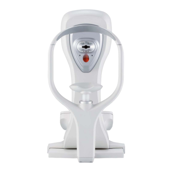
9 Device Description Device Description Overview of Device Components Side - view measure head Joystick Chin rest Function keys XY-base Display Control knob Printout slot Abb. 9-1: Corvis® ST: Side view Instruction Manual Corvis® ST (G/72100/XXXX/EN 1019 Rev01) 13 / 80... - Page 20 9 Device Description Front - view Head rest On/Off switch Air nozzle / window of the slit lamp Control LED Lens protection glass Mains connection LED to illuminate the eye USB port Marking for the eye height Safety stop Abb. 9-2: Corvis® ST: Front view and connections 14 / 80 Instruction Manual Corvis®...
-
Page 21: Mode Of Operation Of The Corvis® St
9 Device Description Mode of Operation of the Corvis® ST The Corvis® ST is a non-contact tonometer equipped with an optical Pachymetry function. The Corvis® ST measures intraocular pressure without contact with the eye by applying an air puff to the eye. During the air puff the eye gets illuminated by a 9 mm slit through the apex and a built-in high-speed camera records the movement of the eye with more than 4000 images per second. - Page 22 9 Device Description Applied parts 1 Head rest 2 Chin rest Abb. 9-3: Applied parts 16 / 80 Instruction Manual Corvis® ST (G/72100/XXXX/EN 1019 Rev01)
-
Page 23: Start-Up
Attention Incorrect measurements / equipment damage due to a lack training Before first use: Let OCULUS or an authorized dealer train you in the operation of the Corvis® ST. Incorrect measurements / equipment damage due to incorrect set-up ... -
Page 24: Adjustments After An In-House Transport
10 Start-up 10.3 Adjustments after an in-house transport Note Equipment damage due to incorrect lifting If the Corvis® ST is lifted only by the measure head, it can break off. Grab the Corvis® ST from below and the head rest to lift it. 10.3.1 Device set-up ... -
Page 25: Electrical Connection
10 Start-up Unlock the transport safety device if it is locked (1). "Locked" position "Unlocked" position Abb. 10-2: Unlock transport safety device Press down gently on the transportation safety device and turn it counter-clockwise to the "unlocked" position (2). The spring will push the transport safety device up. - Page 26 10 Start-up Note Risk of equipment damage due to incorrect connection If you do not connect the Corvis® ST properly, and the connection is live, the unit can be damaged within a short period of time. Do not use excessive force when connecting the electrical plug. ...
-
Page 27: Daily Operation
10 Start-up 10.5 Daily operation 10.5.1 Switching on the Corvis® ST Make sure that the mains voltage is the same as the voltage specified on the rating plate. Switch on the Corvis® ST with the On/Off Switch (1). 10.5.2 Setting the Safety Stop The safety stop (2) is a lock that prevents the air nozzle from touching... -
Page 28: Switching Off The Corvis® St
10 Start-up 10.5.4 Switching off the Corvis® ST End the current session. Switch off the Corvis® ST with the On/Off Switch (1). Attention Risk of electric shock if the Corvis® ST is not completely disconnected from the mains for transport, cleaning, maintenance, disinfection and re- pair. -
Page 29: Preparing A Measurement
11 Preparing a measurement 11 Preparing a measurement In order to transfer data from the device to your computer/laptop you have to install the following software on your computer: the Corvis® ST program the USB connection must be enabled in the „Settings 2: USB Trans- ... - Page 30 11 Preparing a measurement Component Function Operation Display (1) Shows program screens Serves as a touch screen Lightly press the desired button Control knob Changes the corresponding Turn the knob to the left or right. The selected Parameters parameter is highlighted in blue.
-
Page 31: Display With Touch Screen
11 Preparing a measurement 11.2 Display with Touch Screen In addition to the screen-dependent buttons, you can also use the buttons on the touch screen. The buttons change depending on the function of the display. Lightly press the corresponding buttons on the touch screen to enable the function. -
Page 32: Start Patient Data Management
11 Preparing a measurement 11.3 Start Patient Data Management After you have switched on the computer, it first loads the operating system. Depending on the setting, the Patient Data Management opens automatically. If necessary, press the Corvis® ST icon: The Patient Data Management user interface appears "Functions"... -
Page 33: Importing Patient Data
11 Preparing a measurement 11.4 Importing patient data You can import patient data from a USB flash drive, see sec. 14.5.2, page Note Loss of data due to computer viruses Computer viruses can cause loss of data. Run a virus check before importing data from the USB flash drive. ... -
Page 34: Enter A New Patient
11 Preparing a measurement Recommendation: Import the patient data with the option "Folder". Press the [...] button. (2) In the dialog box, select the directory or the file where the patient data is located: .DAT and .BMP. Confirm your selection with [OK] or [Save]. -
Page 35: Select An Existing Patient
11 Preparing a measurement Manually enter a new patient You can also manually enter a new patient. Press the [New] button to enter a new patient in the Patient Data Management software. Enter the patient's full last name, first name and date of birth in the patient window. - Page 36 11 Preparing a measurement Extended patient search: [Extended] checkbox Click on the Checkbox [Extended]. The screen displays additional search parameters which, for example, reference previous examinations. Proceed as you did when entering the patient name. Abb. 11-6: Advanced search 30 / 80 Instruction Manual Corvis®...
-
Page 37: Perform A Measurement
12 Perform a Measurement 12 Perform a Measurement Perform a measurement for each eye before you save the data. To perform a measurement, you must Start the Corvis® ST program at the computer, sec. 12.1, page 31 Adjust the Corvis® ST, sec. -
Page 38: Adjusting The Corvis® St
12 Perform a Measurement 12.2 Adjusting the Corvis® ST Before starting a measurement, adjust the Corvis® ST. Attention Risk of contact of the patient's eye with the air nozzle Before starting a measurement, make sure the safety stop is set correctly, sec. - Page 39 12 Perform a Measurement Ask the patient to place his or her head on the chin and head rest. 1 Head rest 3 Chinrest 2 Mark eye height Abb. 12-2: Position patient according to the markings The eye height marking (2) between the chin rest and the headrest should be located roughly at the centerline of the patient's eye.
- Page 40 12 Perform a Measurement Move the adjusting base until the patient's eye is focused on the display. If necessary: Adjust the height with the buttons. The auto-tracking function automatically looks for the trigger position. 1 Auto-tracking is activated Abb.
-
Page 41: Fine Adjustment
12 Perform a Measurement 12.2.2 Fine Adjustment Use the information on the display and the joystick to make any fine adjustments. Move the joystick in the direction indicated. Abb. 12-4: Fine Adjustment Example Move the joystick to the right. ... - Page 42 12 Perform a Measurement During the measurement process, you will work with the following display: 1 Display measuringmode Examinated eye 2 Camera image Buttons Abb. 12-6: Measurement procedure Element Function Displaying mode(1) Information about the displaying mode, automatically active Camera image (2) Camera image of the patient´s eye Examinated eye (3) The examinated eye is displayed:...
-
Page 43: Triggering The Measurement
12 Perform a Measurement 12.3 Triggering the measurement A measurement is performed for each eye. The measurement results are then transmitted to the computer/laptop. Depending on what has been preset (see User Guide), the measurement is now either triggered automatically or you must trigger the measurement manually. -
Page 44: Saving Data
12 Perform a Measurement 12.5 Saving data Depending on the installation, your data is transferred to a computer or laptop. You can use the patient data management for your data, sec. 14, page Note Loss of data due to interrupted save If you turn off the Corvis®... -
Page 45: Complete Measurement
12 Perform a Measurement 12.6 Complete measurement With the Corvis® ST program With this menu item, you can select other patients, or can exit the Corvis® ST program. You then return to the patient data management.. Fig. 12-8: Completing a measurment ... -
Page 46: Using Patient Data Management
12 Perform a Measurement 12.7 Using Patient Data Management When you have completed an examination, you can continue processing the patient data in Patient Data Management You can do the following to the patient data rename, sec. 12.7.1, page 40 ... -
Page 47: Data Backup
12 Perform a Measurement Select the "Target" (1) where you would like to export the data. Recommendation: Export the patient data using the "Individual file (U12)" option. Press the [...] button. (2) In the dialog that appears, select the folder or the file to which the patient data should be exported. -
Page 48: Backup Data
12 Perform a Measurement 12.7.4 Backup data Press the [Backup] button on the upper right part in the Patient Data Management user interface. The following dialog appears: [Restore] button [Save] button Display free storage space. Backup data selection Backup folder and button [...] Abb. -
Page 49: Automatic Backup
12 Perform a Measurement Confirm your selection with [OK]. To import the data, press the [Restore] button (1). All data in the appropriate directory are copied to the Patient Data Management software. 12.7.6 Automatic backup In addition to the manually performed backup, it is also possible to automatically run a backup when exiting the Patient Data Management system. -
Page 50: Working With The Corvis® St Program
13 Working with the Corvis® ST program 13 Working with the Corvis® ST program If you started the Corvis® ST program by selecting an examination in the Patient Data Management program, the selected examination is loaded in the Corvis® ST program. If not, you may need to load an examination first, see sec. -
Page 51: View Patient And Examination Data (1)
13 Working with the Corvis® ST program 13.1 View patient and examination data (1) The patient and examination data are displayed on every screen of the Corvis® ST program. 13.2 Working with the Menu Bar (7) You can access the menu bar from any screen of the Corvis® ST. Abb. -
Page 52: Menu Item "Display
13 Working with the Corvis® ST program 13.2.3 Menu item "Display" Display different presentations You can display different presentations of an examination. Press the appropriate button. For more information about the menu item „Display“, refer to the User Guide 13.2.4 Menu item "Export“... -
Page 53: View Specific Images Of The Cornea (4)
13 Working with the Corvis® ST program 13.4 View specific images of the cornea (4) You can view the images of the cornea at specific times; A1 (Applanation 1), HC (Highest Concavity) and A2 (Applanation 2). Press the appropriate button. Instruction Manual Corvis®... -
Page 54: Perform A Measurement With The Corvis® St Unit
14 Perform a measurement with the Corvis® ST unit 14 Perform a measurement with the Corvis® ST unit You can perform an examination with the Corvis® ST unit alone and can directly save the patient and examination data there. The procedure for this is as follows: ... -
Page 55: Entering Patient Data
14 Perform a measurement with the Corvis® ST unit 14.2 Entering Patient Data If the Corvis® ST program is started with the computer, you don not have to enter patient data. When you turn on the Corvis® ST, you see the Patient Data Management first. -
Page 56: Entering New Patient
14 Perform a measurement with the Corvis® ST unit 14.2.1 Entering new Patient Press the [New Patient] button in the patient data menu to enter a new patient. The following screen appears: Abb. 14-2: Touch-screen keyboard, enter patient data ... -
Page 57: Select An Existing Patient
14 Perform a measurement with the Corvis® ST unit Enter the date of birth and confirm with [Enter]. If you have entered the correction calculation per „Spoerl“ you must enter the patient’s date of birth so that the correction is calculated correctly. You will be asked if you want to save the new patient data. -
Page 58: Perform A Measurement
14 Perform a measurement with the Corvis® ST unit 14.3 Perform a Measurement To prepare the measurement, proceed as described in sec. 11.1, page 23 sec. 11.2, page 25 Perform the measurement as follows: Select the measuring mode, sec. 14.3.1, page 52 ... -
Page 59: Re-Use Examination Data
14 Perform a measurement with the Corvis® ST unit 14.5 Re-use examination data 14.5.1 Delete a Patient or an Examination If you want to delete a patient or an examination: Select the patient in question. Press the [Pat./Exam Delete] button. Abb. - Page 60 14 Perform a measurement with the Corvis® ST unit Open the cover with the display. Abb. 14-6: Open the cover with the display Pull out the USB flash drive. Plug the USB flash drive into your computer. Now you can import the data into the Patient Data Management program, sec.
-
Page 61: Cleaning, Disinfection And Maintenance
15 Cleaning, Disinfection and Maintenance 15 Cleaning, Disinfection and Maintenance This chapter describes how to clean, disinfect, and maintain the Corvis® ST. Sterilization is not required. Heed the product descriptions and instruction manuals of products and equipment you use to care for, clean, and disinfect the unit and/ or its accessories. -
Page 62: Clean The Front Panel
15 Cleaning, Disinfection and Maintenance 15.1.1 Clean the front panel 1 Head rest Lens protection glass 2 Air nozzle Chin rest Abb. 15-1: Clean lens protection glass and air nozzle Clean head (1) and chin (4) rests The Corvis® ST can remain switched on for this cleaning step. During the measuring process, sweat, cosmetics, etc. - Page 63 15 Cleaning, Disinfection and Maintenance Clean lens protection glass (3) The openings in the housing for the optics are covered by protective glass covers which must be kept dust and dirt-free. Clean the lens protection glass with a lint-free cloth moistened with alcohol.
-
Page 64: Disinfection
15 Cleaning, Disinfection and Maintenance Cleaning the display Clean the display using a dry, lint-free cloth. 15.2 Disinfection Required materials: Disinfection and Cleaning Kit (included), Alternatively: Pursept®-A Xpress disinfectant wipes, Merz+Co company; D-60318 Frankfurt: Tel: +49 69 1503 1; Fax: +49 (69) 596 21-50 E-mail: merzpr@merz.de ... -
Page 65: Maintenance
15 Cleaning, Disinfection and Maintenance Note Equipment damage due to disinfectant solution The disinfectant solution may damage the finish if it is sprayed directly on it. Only spray the disinfectant solution onto a cleaning cloth, not directly on the device 15.3 Maintenance ... -
Page 66: Insert New Printing Paper Roll
15 Cleaning, Disinfection and Maintenance 15.5 Insert new printing paper roll Open the cover with the display. Abb. 15-4: Open the cover with the display The following screen appears: Abb. 15-5: Change printer paper You can advance and reverse the printer paper by pressing the buttons "Printer Feed"... - Page 67 15 Cleaning, Disinfection and Maintenance Press "Feed Back" to reverse, or roll back the printer paper. Printer roller Metal pin White slot Holder Abb. 15-6: Remove and insert printer roller Remove the feed roller (1) from the holder (4). ...
-
Page 68: Dismantling, Transport And Storage
16 Dismantling, Transport and Storage 16 Dismantling, Transport and Storage Before you transport or store the Corvis® ST you may have to dismantle it properly and lock the transport safety device. 16.1 Removal Switch off the Corvis® ST with the On/Off Switch (3). ... -
Page 69: Transport And Storage
16 Dismantling, Transport and Storage Lock the transport safety device (2). Press down gently on the transport safety device and turn it counter- clockwise to the "unlocked" position (3). The transport safety device must be engaged. Opening of the transport safety device Spring "Locked"... -
Page 70: Disposal Of Used Devices
17 Disposal of Used Devices Note Equipment damage due to incorrect lifting If the Corvis® ST is lifted by the head rest, it can break off. Grab the Corvis® ST from below to lift it. Equipment damage due to incorrect transport and improper storage ... -
Page 71: Troubleshooting
18 Troubleshooting 18 Troubleshooting Attention Persons or equipment damage due to incorrect troubleshooting Do not plug in or unplug any cables while the Corvis® ST is switched If an error occurs which you are unable to correct by following the instructions below, label the device as "out of order"... -
Page 72: Terms Of Warranty And Servicing
On request, and for this purpose, OCULUS will supply authorized persons with spare parts lists and additional descriptions. Make sure that only original OCULUS parts are used for service and maintenance. 66 / 80 Instruction Manual Corvis® ST (G/72100/XXXX/EN 1019 Rev01) -
Page 73: Technical Data
20 Technical Data 20 Technical Data Measure Mode IOP + pachymetry Tonometer Measuring range 6 to 60 mmHg Working distance 11 mm Internal fixation light red LED Scheimpflug camera Frame Rate 4330 frames/s Measuring range 8.5 mm horizontally Pachymeter measuring range 300 to 1200m Measuring points 576 per image... - Page 74 20 Technical Data Transport Ambient temperature range -40 — +70 °C Relative humidity, including condensation 10 — 95% Air pressure range 500 — 1060 hPa Measuring head Power supply 15 V DC; 6 A Max. power consumption 26 W Power adapter15 V DC Mean Well (05150285) Mains connection 100 - 240 V...
-
Page 75: Appendix
EMC, and must be installed and operated according to the EMC-Instructions contained in the accompanying pa- perwork. No special measures need be observed in respect of OCULUS devices and systems. Portable and mobile RF-communications devices can interfere with electrically operated medical devices. - Page 76 21 Appendix Warning The use of accessories, transducers and cables not specified by OCULUS (for example as replacement parts) may result in increased emissions or decreased immunity of the Corvis® ST. Use only the original accessories, transducers and cables specified by OCULUS.
-
Page 77: Guidance And Manufacturer's Declaration - Electromagnetic Emmisssions And Immunity For The Corvis® St
Guidance and manufacturer´s declaration electromagentic emmissions IEC 60601-1-2: 2015, based to table 1 The OCULUS Corvis® ST is intended for operation in the electromagnetic environment specified below. The user of the Corvis® ST should ensure that it is being used in such an environment. - Page 78 21 Appendix Electromagentic immunity, IEC 60601-1-2: 2015, based on table 4 Immunity test IEC 60601 Compliance level Electromagnetic environment - test level guidance Electrostatic discharge ± 8 kV contact ± 8 kV Floors should be made of wood (ESD) ± 15 kV or concrete or covered with ±...
- Page 79 21 Appendix Electromagentic immunity, IEC 60601-1-2: 2015, based on table 4, 5 Immunity test IEC 60601 Compliance level Electromagnetic environment - Guidelines test level Portable and mobile RF communications equip- ment should be used no closer to any part of Corvis®...
- Page 80 21 Appendix Recommended separation distances between portable and mobile RF communications equipment and the Corvis® ST, IEC 60601-1-2:2007, table 6 The Corvis® ST in intended for us e in an electromagnetic environment in which radiated RF disturbances are controlled. The customer or the user of the Corvis® ST can help prevent electromagnetic interference by main- taining a minimum distance between portable and mobile RF communications equipment (transmitters ) and the Corvis®...
-
Page 81: Description Of The Connection
21 Appendix 21.4 Description of the Connection Corvis® ST USB Isolator Cable Power supply adapter (05150285) Computer/PC/Laptop Mains connection Instruction Manual Corvis® ST (G/72100/XXXX/EN 1019 Rev01) 75 / 80... -
Page 82: Data Sheet Power Supply Adapter (05150285)
21 Appendix 21.5 Data sheet Power Supply Adapter (05150285) 76 / 80 Instruction Manual Corvis® ST (G/72100/XXXX/EN 1019 Rev01) - Page 83 21 Appendix Instruction Manual Corvis® ST (G/72100/XXXX/EN 1019 Rev01) 77 / 80...
- Page 84 21 Appendix 78 / 80 Instruction Manual Corvis® ST (G/72100/XXXX/EN 1019 Rev01)
- Page 85 21 Appendix Instruction Manual Corvis® ST (G/72100/XXXX/EN 1019 Rev01) 79 / 80...
- Page 86 Manufacturer and Service Address Headquarters: OCULUS Optikgeräte GmbH Münchholzhäuser Straße 29 • 35582 Wetzlar • GERMANY Tel. +49 641 2005-0 • Fax +49 641 2005-255 E-Mail: sales@oculus.de • www.oculus.de USA: OCULUS, Inc. 17721 59th Avenue NE • Arlington • WA 98223 Tel.
Need help?
Do you have a question about the Corvis ST and is the answer not in the manual?
Questions and answers