Table of Contents
Advertisement
Quick Links
Advertisement
Table of Contents

Related Manuals for OCULUS Easyfield


Summary of Contents for OCULUS Easyfield
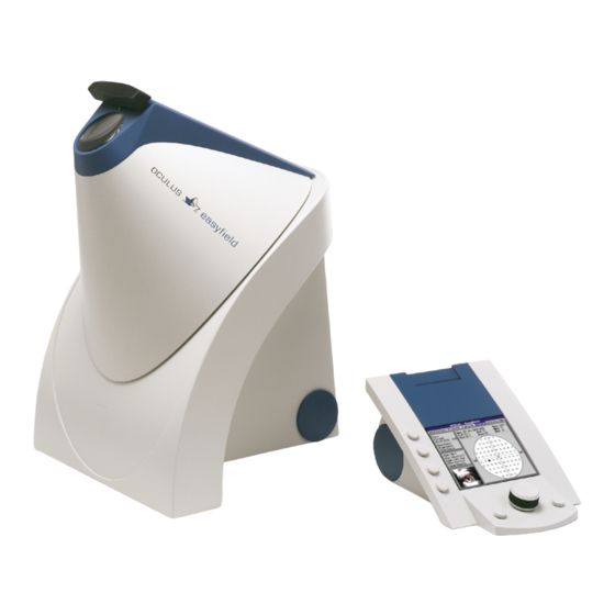
- Page 1 Easyfield Service manual Copyright by S/56930/0102/e...
-
Page 2: Table Of Contents
2 Service manual Easyfield Table of contents Table of contents...................... 2 Safety Precautions ....................3 Component description ....................3 System requirement ....................4 PC ........................4 Mains power ...................... 4 System setup ......................4 PC connection ....................4 Wiring ....................... 4 The basic operation principal of the system .............. -
Page 3: Safety Precautions
3 Service manual Easyfield Safety Precautions OCULUS Easyfield sensitive • Protect the unit also from dust, extreme measuring instrument. Repairs must be done temperatures, and water. by authorized persons and with original parts • The unit must be used with the proper from OCULUS only. -
Page 4: System Requirement
115200Baud. 4.2 Wiring Caution: Do not connect or disconnect any 9 pin (one to one) extention cable (D plugs). cable while the PC or the Easyfield is Connect the Easyfield unit with the power switched on! supply. -
Page 5: The Basic Operation Principal Of The System
5 Service manual Easyfield The basic operation principal of the system A LED-bar (3) illuminates the cupola (4) Using the response button (8) the • • indirectly. patient signals seeing or not seeing the A testpoint (5) is presented to the testpoint. -
Page 6: Easyfield
6 Service manual Easyfield Easyfield 6.1 Opening the housing Before opening the perimeter disconnect all plugs it is connected to. Screws Figure 3 Unscrew the four screw at the back of the housing by pulling it in the direction as unit and remove the back part of the marked on the picture. - Page 7 7 Service manual Easyfield LED-board Cupola moving axis CCD-board EF01 board Figure 5 LED row for back- ground illumination Infrared diode Figure 6...
-
Page 8: Remove The Cupola
8 Service manual Easyfield 6.2 Remove the cupola Two Allen screws Figure 7 Unplug the flat ribbon cables from the EF01 board to the testpoint board and cut the cable ties. CCD board Screws holding the CCD board LED board... -
Page 9: Set Up The Ccd Image
Service manual Easyfield 6.2.1 Set up the CCD image The CCD camera has been set up by cable only will destroy the board. The OCULUS for best picture. If the unit has to pictures position changed be dismount for repairing it is possible that unlocking the screws 1 (cf. -
Page 10: Dismounting The Ccd Board
10 Service manual Easyfield 6.2.2 Dismounting the CCD board Remove the screws described in Figure 8 and pick up the CCD board from its holder. Pin 1 Figure 10 (Front side) Figure 12 (Back side without CCD chip) Figure 11 (Back side) If the camera picture looks like a chessboard can be defect. -
Page 11: Board Description
11 Service manual Easyfield 6.2.3 Board description 6.2.4 EF01 board The internal functions of the measuring values are stored on the EF01 boards device controlled Eeprom. Microcontroller. controls perimetric Caution: If the EF01 board has to be measurement, data... -
Page 12: Ccd Board
12 Service manual Easyfield 6.2.5 CCD board This board has a single CCD chip which resolution of 582x752 Pixel The board is produces a picture of the patient’s eye. This directly connected with the EF01 board. ½ inch CCD (Sony ICX039BLA) uses a... -
Page 13: Led Board
13 Service manual Easyfield 6.2.6 LED board This board contains all the testpoint LEDs the testpoints. Also this board has got a and fixation marks which are projected connector for the background illumination inside the cupola. This board is connected... -
Page 14: Power Supply
14 Service manual Easyfield 6.3 Power supply The power supply type SW172 needs 100- 240V with 50-60Hz input. The output voltage is +12V, 2,75A. 6.4 Hand held unit 6.4.1 Opening the housing To open the housing just remove the printers on Figure 15. -
Page 15: Control Board
15 Service manual Easyfield Control board Control button board Figure 17 6.4.2 Control board The control board as it named controls the examination program and has got space for perimeter completely. It contains the whole 40000 examinations. Button, Control... -
Page 16: Troubleshooting
16 Service manual Easyfield Troubleshooting Malfunction Possible cause Remedy CCD picture looks like a CCD board is defect The CCD board has to be chessboard or has got vertical exchanged (cf. 6.2.2, page 10) or horizontal stripes CCD picture is dark... -
Page 17: Appendix
17 Service manual Easyfield Appendix 8.1 List of parts piece construction no. Name material 56930-03-000 Easyfield 56930-03-001 Basis 56930-03-003 Lever AlMg3 56930-03-005 Axis Nirosta 56930-03-009 Cross carrier 56930-03-010 Interface holder St37K 56930-03-011 Brace St37K 56930-03-012 Flat support Zinkcor 56930-03-013 Reflector PS + 0.1% yellow... - Page 18 18 Service manual Easyfield 05400050 Cup spring 10x5.2x0.5x0.75 SN2000 04020775 Hexagonal nut M4 DIN934 zinc-coated 04020775 Hexagonal nut M4 DIN934 zinc-coated 04030030 Washer A3.2 DIN125 04030030 Washer A3.2 DIN125 04030070 Washer A4.3 DIN125 zinc-coated 04030070 Washer A4.3 DIN125 zinc-coated 04030105 Washer 6.3x10x0.8...
Need help?
Do you have a question about the Easyfield and is the answer not in the manual?
Questions and answers