Table of Contents
Advertisement
Quick Links
Advertisement
Table of Contents

Related Manuals for aerauliqa QRCE Series


Summary of Contents for aerauliqa QRCE Series
- Page 1 INSTALLATION, OPERATION AND MAINTENANCE MANUAL VENTILATION UNIT WITH HIGH EFFICIENCY HEAT RECOVERY SERIES QRCE The data of this manual may be subject to updating. We reserve the right to make modification without prior notice. MIUM0018_REV06_ QRCE_20180312-MIUM-ENG-AQ AQ_001523_02_0721...
- Page 2 Dear Customer, Thank you for having purchased an Aerauliqa product. It is the result of many years of experience, research and has been made with top quality materials and highly advanced technologies. The CE mark guarantees that the machine meets the European Standards regarding safety.
-
Page 3: Installation
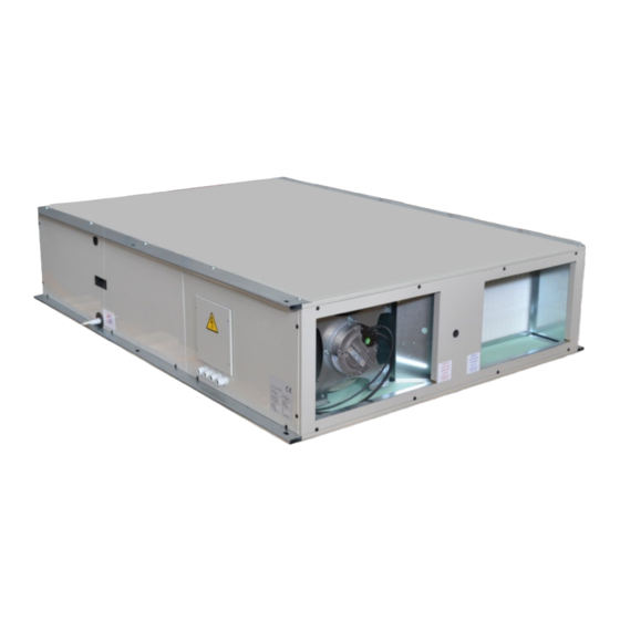
SYMBOLOGY ATTENTION DANGER HIGH RISK OF ELECTRIC SHOCK ATTENTION: AUTHORIZED PERSONNEL ONLY 1 – I NTRODUCTION pag. 4 2 - D IMENSIONS AND EIGHTS pag. 5 3 – H ANDLING RANSPORT AND TORAGE pag. 8 4 – I & C NSTALLATION ONNECTION pag. - Page 4 Working environment shall be characterized by air temperature not lower than -20°C and not higher than 45°C and by relative humidity not higher than 95%. For special or out of range applications first contact Aerauliqa for a feasibility analysis. This unit, in its basic configuration, is essentially composed of (fig. 1) : 1 –...
- Page 5 • This manual together with separate wiring diagram and control instructions (supplied with the unit) must be kept in a dry place and ready to hand for future consultation when required. • This manual has been compiled to ensure that the unit is installed in the correct way and to supply comprehensive information about how to correctly use and service the appliance.
- Page 6 2 – D IMENSIONS AND EIGHTS 2.1 Dimensions (horizontal version unit) The following table, referred to the figure, shows dimensions and weights of QRCE series (horizontal version) and its accessories. Fresh air Supply air QRCE (CDX) Return air Exhaust air...
- Page 7 2.2 Dimensions (vertical version unit) The following table, referred to the figure, shows dimensions and weights of QRCE series (vertical version) and its accessories. QRCE (CDX) Fresh air Supply air Return air Exhaust air Vertical configurations C : supply air at lower and right side looking at the electrical panel (like in the drawing above)
-
Page 8: Handling , Transport And Storage
3 – H ANDLING RANSPORT AND TORAGE 3.1 Packing Each unit is put on bench and covered with cardboard packaging; the packaging shall remain intact until the moment of installation. It is allowed to stack up max one similar unit or a smaller one over the ground unit. Optional or optional sections not mounted for technical reason (for instance, in order to avoid damage of protruding parts) are supplied in fitted packing fixed externally or internally to the unit. -
Page 9: Installation And Connection
3.3 Check at reception Upon reception of the unit, we suggest that a complete control is carried out, to verify that the unit is intact and complete, and no damage has been sustained during transport. Any eventual damage revealed must be communicated to the carrier, demonstrating the reserve clause within the transport documents, specifying the type of damage. -
Page 10: Preliminary Operations
4.2 Preliminary operations • Be sure of perfect functionality of all components of the unit. • Check that unit is provided with installation instructions and with its ordered options. • Move the unit and its possible optional sections to the installation place as close as possible. •... - Page 11 • Once support feet are mounted, unit shall be turn to be placed vertically; for this purpose, use the upper longitudinal bracket and operate as shown on fig. 4a. The rotation of the unit shall be done in complete safety condition.
- Page 12 • Position the unit in a point where the condensation discharge may occur easily; give a 3° min slope towards the point of water discharge; this requirement applies to both horizontal and vertical version. • Leave minimum gap spaces as shown on following figg. 6 and 7. They are needed for fully accessibility to the unit in order to carry out all services in safety condition.
- Page 13 • For horizontal version unit, use M8 threaded bars (or similar) crossing each supporting point of the unit bracket; always interpose vibration dampers between unit bracket and bars (fig. 8). Threaded bar filettata Washer Vibration damper damperivibrante Washer Fig. 8 Locknut •...
- Page 14 4.4 Installation of roof cover (TPR-H, TPR-V, TPR-CH, TPR-CV) • In the event that roof covers are supplied apart to be mounted later than the unit and/or its external sections CCS/CDX, it is always possible to install them on the existing unit/sections. •...
- Page 15 4.5 Installation and coupling of external sections CCS/CDX/PLM • The external sections are directly coupled to the basic unit by air intakes & outlets panels (by supply air/return air panel for CCS/CDX, by both panels for PLM, depending on PLM purpose); these sections are provided with brackets for ceiling mounting or support feet (supplied apart and to be mounted as shown in the sequence of figg.
-
Page 16: Air Duct Connections
4.5.1 Air duct connection layout (multiport plenum PLM) • PLM plenum is provided with n°10 possible air connections of which n° 6 closed by insulated plates (A) fixed by selfdrilling screws, as shown on fig. 10a. • in order to get the desired air inlet/air outlet layout, move opportunely and block again the plates on the connections really not used;... - Page 17 4.6.1 Installation of damper (SKR1, SKR2 supplied apart) • Each damper is provided with holes on its coupling flange and supplied kit composed of adhesive perimetric gasket (A) and selfdrilling screws (B), as shown on fig. 10b. • Apply the gasket all around the perimeter of the flange, place the damper in correspondence with the interested air intake/outlet so that its shaft is accessible and can't interfere with unit access doors or other functional elements, then fix by the selfdrilling screws.
-
Page 18: Electrical Connections
4.7.2 Water coil connection (CCS) • Water coil is provided with GAS male threaded connections. • The tightening must be carried out with extreme care to avoid damage to the copper headers. • The path of piping shall not interfere with scheduled and not scheduled maintenance operations. •... -
Page 19: Wiring Diagrams
5 – W IRING IAGRAMS Each unit is provided with internal wiring diagram, characterized by specific code. To match code and unit model see the following table : QRCE Model Wiring diagram code AMF0008070 1000-1500-2000 AMF0008071 3000-4000 AMF0008072 In the back of electrical box panel it is also printed the basic unit external wiring diagram, connection to be carried out by the installer;... - Page 20 Fig. 12a Fig. 12b Once the door is open, the slipping of filter elements is prevented by a filter locking plate to be turned 90°(use a Phillips head screwdriver); after remounting filter elements, turn the locking plate in the opposite direction to the contact with filter frame, then block it (fig.
- Page 21 Fig. 13a Remove one end panel at a time using an AW20 head tool to unscrew. For horizontal unit, once unscrewed, preventively turn the panel (1) and then remove it by side (2), in order to not interfere with the corner vertical supporting bar. For vertical unit, once unscrewed, directly move the panel upwards.
-
Page 22: Heat Recovery
7.2 Scheduled yearly check Check all electrical devices, check that all electrical connections are well tightened. Similarly, check all mechanical and water connections. 7.2.1 Heat recovery No particular maintenance operation is needed but the visual check of perfect cleaning and integrity of heat exchange surface. - Page 23 7.3.2 Removal and replacement of by-pass actuator By-pass device is inspected by removal of middle panel bewteen the two end panels for special access to filters. For size 3000 and 4000 also remove temporarily the intermediate support (see previous 4.3). To remove this panel operate as described below (fig.
-
Page 24: Troubleshooting
To install a new actuator operate according to the opposite sequence, taking care of matching the damper shaft in the same position when the previous actuator has been removed. To re-mount operate as described below : 1) mount and fix the middle panel (for 3000 and 4000 model install again and adjust the intermediate support) 2) fix the internal screws A 3) insert and fix each of the filter panel 7.3.3 Manual reset of the internal electric heater(s);... - Page 25 During disconnection of the unit, avoid gas leakage or liquid spillage on environment, especially if the water has additives like glycol. For dismissing and disposal, deliver the units to specialized centers according to your national laws. AERAULIQA SRL Registered office: via Mario Calderara 39/41, 25018 Montichiari, Brescia...
Need help?
Do you have a question about the QRCE Series and is the answer not in the manual?
Questions and answers