aerauliqa QR280E Instructions For Installation, Use And Maintenance Manual
Hide thumbs
Also See for QR280E:
Table of Contents
Advertisement
Quick Links
Advertisement
Table of Contents

Subscribe to Our Youtube Channel
Related Manuals for aerauliqa QR280E


Summary of Contents for aerauliqa QR280E
- Page 1 QR280E installation, usE and MaintEnancE Manual...
-
Page 2: Product Information
• Use original spare parts only for repairs. 3 PRoduct infoRMation 3.1 General This is the Installation, Use and Maintenance Manual of the heat recovery ventilation units, models QR280E and QR590E. This manual consists of basic information and recommendations concerning installation, commissioning, use and service operations to ensure a proper fail-free operation of the unit. The key to proper, safe and smooth operation of the unit is to read this manual thoroughly, use the unit according to given guidelines and follow all safety requirements. -
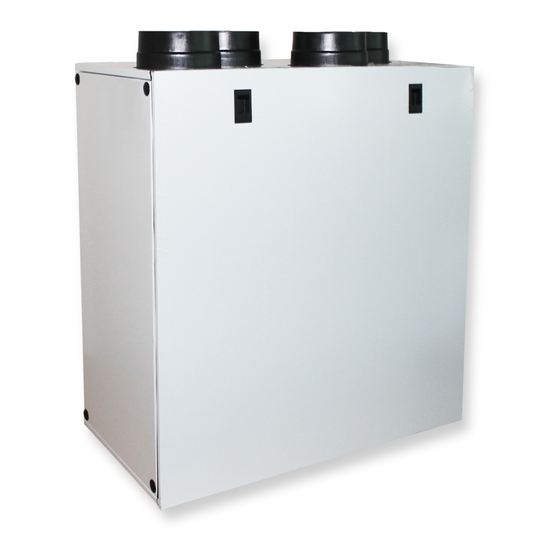
Page 3: Dimensions And Weight
The factory setting is LEFT. QR280A Intake air from outside Exhaust air to outside LEFT Supply air to inside Extract air from inside Extract air from inside Supply air to inside RIGHT Exhaust air to outside Intake air from outside fig. 3.a Connections in LEFT and RIGHT orientation - QR280E. -
Page 4: Transport And Storage
QR590E Intake air from outside Exhaust air to outside LEFT Supply air to inside Extract air from inside Extract air from inside Supply air to inside RIGHT Exhaust air to outside Intake air from outside fig. 3.b Connections in LEFT and RIGHT orientation - QR590E. To set the RIGHT orientation of the machine: • Modify the orientation on the CTRL-DSP (§ 7.2 - Installer menu: 3 Machine Orientation). •... - Page 5 5.3 installation The unit must be installed in the following position. it is important that the unit is vertical in order for the condensation drainage to work properly. QR280E fig. 5.a fig. 5.b fig. 5.c Spacers fig.
- Page 6 Ø125mm Ø125mm fig. 5.h 5.a Prepare the surface where the unit is to be mounted. Make sure that the surface is flat, levelled and that it supports the weight of the unit. Perform the installation in accordance with local rules and regulations. 5.b Drill the holes in the wall. 5.c Use appropriate wall plugs and screws (not supplied). 5.d Fix the 2 spacers on the back of the unit. 5.e Hang the unit to the wall by means of the fixing brackets. 5.f Screw safely.
- Page 7 fig. 5.l Spirit level Spirit level fig. 5.m Ø160mm Ø160mm fig. 5.n 5.j Prepare the surface where the unit is to be mounted. Make sure that the surface is flat, levelled and that it supports the weight of the unit. Perform the installation in accordance with local rules and regulations. Use the wall fixing bracket as template to indicate where to drill the holes in the wall: make sure it is at spirit level. Use appropriate screws and wall plugs (not supplied) to fix the wall fixing bracket. 5.k Fix the 2 spacers on the back of the unit. 5.l Hook the unit at its bracket. 5.m Make sure it is at spirit level and fix it by means of the safety screw. 5.n Connect the unit to the duct system.
- Page 8 5.4 Precabled electric connections WaRninG Make sure that the mains supply to the unit is disconnected before performing any installation, service, maintenance or electrical work! WaRninG The installation and service of the unit and complete ventilation system must be performed by an authorized installer and in accordance with local rules and regulations.
- Page 9 5.5 additional electric connections WaRninG Make sure that the mains supply to the unit is disconnected before performing any installation, service, maintenance or electrical work! WaRninG The installation and service of the unit and complete ventilation system must be performed by an authorized installer and in accordance with local rules and regulations.
-
Page 10: Setting Fan Speed
6. a-d below show performance curve at different settings of the 0-10V signal to the motors. Consumption refers to the 2 motors. figures 6. b-e indicate the data of the enthalpic heat exchanger. tables 6. c-f indicate the sound level at the different speeds. QR280E Curve Speed % A (min) G (max) fig. - Page 11 Lw dB - SOUND POWER OCTAVE BAND Lp dB(A) Speed 100% Intake Supply Extract Exhaust Breakout Lw dB - SOUND POWER OCTAVE BAND Lp dB(A) Speed 80% Intake Supply Extract Exhaust Breakout Lw dB - SOUND POWER OCTAVE BAND Lp dB(A) Speed 60% Intake Supply Extract Exhaust Breakout Lw dB - SOUND POWER OCTAVE BAND Lp dB(A) Speed 40% Intake Supply Extract Exhaust Breakout table 6.c Sound level: dBA figures are average spherical free-field, for comparitive use only.
- Page 12 QR590E Curve Speed % A (min) G (max) fig. 6.d Intake curve according to Reg. 1253/2014 (ErP). Product tested without filter F7. Portata d’aria - m Thermical efficiency curve Curva di efficienza termica fig. 6.e Data of the enthalpic heat Curva di efficienza igrometrica Hygrometric efficiency curve exchanger.
- Page 13 Lw dB - SOUND POWER OCTAVE BAND Lp dB(A) Speed 100% Intake Supply Extract Exhaust Breakout Lw dB - SOUND POWER OCTAVE BAND Lp dB(A) Speed 80% Intake Supply Extract Exhaust Breakout Lw dB - SOUND POWER OCTAVE BAND Lp dB(A) Speed 60% Intake Supply Extract Exhaust Breakout Lw dB - SOUND POWER OCTAVE BAND Lp dB(A) Speed 40% Intake Supply Extract Exhaust Breakout table 6.f Sound level: dBA figures are average spherical free-field, for comparitive use only. 6.2 Before starting the system When the installation is finished, check that: • Filters are mounted correctly.
-
Page 14: Operation
LEFT ORIENTATION INTAKE EXTRACT Intake air from outside Exhaust air to outside Supply air to inside Extract air from inside fig. 7.a QR280E temperature probes. fig. 7.b QR590E temperature probes. In case of RIGHT orientation, follows instructions as per § 3.3 - Fig. 3.a and Fig. 3.b in order to get the temperature probes operate correctly. fig. 7.c CTRL-DSP DATE: shows the current date shows ERROR ALARM (see §7.3 to check the type of error) -
Page 15: User Menu On Ctrl-Dsp
When powered on, the CTRL-DSP displays as follows: fig. 7.d CTRL-DSP operation screen The speed (1-2-3) can be manually changed using or . 7.1 user Menu on ctRl-dsP To enter the User Menu press OK or ESC. To exit the User Menu press ESC or wait for about 60 seconds. Select the menu item using or . User Menu Press OK to enter. - Page 16 It allows to select the maximum speed (Boost). User Menu Press OK to select. 1 Mode Selection Choose NO or YES using or . 2 Boost Press OK to select and go back to the previous menu. 3 Boost Duration Factory setting (DEFAULT): NO. 4 Reset FILTER Alarm Boost speed can be adjusted during the installation.
-
Page 17: Installer Menu On Ctrl-Dsp
It allows to set the time slots and the operating speeds throughout the week when the unit is User Menu set to Normal Mode 3V. 1 Mode Selection Press OK to select. 2 Boost Choose NO or YES using or . 3 Boost Duration Press OK to select. 4 Reset FILTER Alarm Factory setting (DEFAULT): NO. - Page 18 It allows to select one language among English, Italiano, Deutsch, Čeština, Slovenský, Français, Installer Menu Español, Nederlandse, 中国, Magyar and Русский. 1 Language Press OK to enter. 2 Date/time Select the language using or . 3 Machine orientation Press OK to select. 4 Normal Mode Factory setting (DEFAULT): English.
- Page 19 To be selected only in case an external heating element (not supplied with the unit) is used. Installer Menu Press OK to enter. 8 Heating 10 Speed setting “1 Heater” 11 Airflow Balancing Press OK to enter. 12 F7 filter Choose NO/PRE/POST using or . 13 Filter Alarm interval Press OK to select.
- Page 20 Press OK to select. 12 F7 filter Factory setting (DEFAULT) for QR590E: YES. 13 Filter Alarm interval Factory setting (DEFAULT) for QR280E: NO. It allows to set the Filter Alarm period: the system has a timer which activates the Filter Installer Menu warning (Fig. 7c - ) on the LCD at regular intervals.
- Page 21 It allows to activate a short operation cycle of the fans at 100% speed for twice in a day. Installer Menu Press OK to enter. 15 Constant Pressure Choose NO or YES using or . 17 Periodic purge Factory setting (DEFAULT): NO. 18 Working Hours Counter 19 ModBus settings If “YES” the following submenu items are displayed: 20 Save settings 1 Periodic purge length It allows to set the purge duration. Press Ok to select. The setting range is: 1 ÷ 5 minutes.
-
Page 22: Remote Enable
It allows to set the LCD contrast. Installer Menu Press OK to enter. 21 Load Settings Increase/decrease the contrast using or . 22 Restore Default Settings Press OK to confirm. 23 Contrast 24 Debug page It shows the internal functional parameters of the unit. Installer Menu Press OK to enter. -
Page 23: Maintenance And Service
8.1 components list QR280E G4 FILTER HEAT EXCHANGER THERMISTOR FAN, INTAKE AIR FAN, EXHAUST AIR ELECTRICAL CONNECTION BOARD ADDITIONAL CABLE ENTRY CONTROL CABLE SUPPLY CABLE CABLE FOR REMOTE SENSOR internal components fig. 8.a QR280E QR590E G4 FILTER F7 FILTER SE NON SPECIFICATO: FINITURA: INTERRUZIONE NON SCALARE DISEGNO REVISIONE QUOTE IN MILLIMETRI BORDI NETTI FINITURA SUPERFICIE: TOLLERANZE:... -
Page 24: Maintenance
Make sure that the mains supply to the unit is disconnected before performing any installation, service, maintenance or electrical work! QR280E • Keep the unit surface free from dust. • Clean the filters with a vacuum cleaner following the below illustrations (Fig. 8.c-d-e-f) when the FILTER signal (Fig. 7.c - is displayed on LCD. - Page 25 The installation and service of the unit and complete ventilation system must be performed by an authorized installer and in accordance with local rules and regulations. QR280E • Keep the unit surface free from dust. • Clean the filters with a vacuum cleaner following the below illustrations (Fig. 8.k-l-m-n) when the FILTER signal (Fig. 7.c - is displayed on LCD.
- Page 26 fig. 8.m fig. 8.n • Clean the heat exchanger every year with a vacuum cleaner. The actual need to perform this operation may vary depending on indoor and outdoor ambient conditions and on frequency of filter cleaning (Fig. 8.k-l-o-p). fig. 8.o fig. 8.p • Clean the fans every year with a vacuum cleaner. The actual need to perform this operation may vary depending on indoor and outdoor ambient conditions and on frequency of filter cleaning. Do not move the motor balance clips (Fig. 8.k-l-o-q). fig.
- Page 27 fig. 8.r fig. 8.s fig. 8.t fig. 8.u • Clean the heat exchanger every year with a vacuum cleaner following the below illustrations Fig. 8.r-s-v. The actual need to perform this operation may vary depending on indoor and outdoor ambient conditions and on frequency of filter cleaning. fig. 8.v • Clean the fans every year with a vacuum cleaner following the below illustrations Fig. 8.r-s-w. The actual need to perform this operation may vary depending on indoor and outdoor ambient conditions and on frequency of filter cleaning. Do not move the motor balance clips.
-
Page 28: Troubleshooting
8.5 troubleshooting Fans do not start 1. Check that main supply gets to the unit. 2. Check that all connections are working (all connections in terminal box and fast couplings of intake and exhaust air fans). Reduced airflow 1. Check setting of fan speed on the CTRL-DSP (controller supplied). 2. - Page 29 NOTE...
- Page 30 NOTE...
- Page 31 10. Direttiva ErP - Regolamenti 1253/2014 - 1254/2014 ErP Directive - Regulations 1253/2014 - 1254/2014 a) Marchio - Mark AERAULIQA AERAULIQA b) Modello - Model QR280E QR590E c) Classe SEC - SEC class c1) SEC climi caldi - SEC warm climates kWh/m -14,3...
Need help?
Do you have a question about the QR280E and is the answer not in the manual?
Questions and answers