Table of Contents
Advertisement
Quick Links
G
Installation Manual (installer & user)
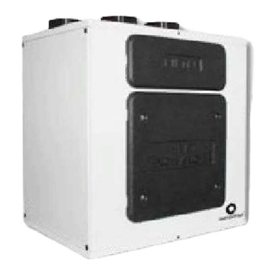
QR400ABP - Heat Recovery Ventilation Unit
Read this manual carefully before using the product and keep it in a safe
place for reference as necessary.
This product was constructed up to standard and in compliance with
regulations relating to electrical equipment and must be installed by
technically qualified personnel.
The manufacturer assumes no responsibility for damage to persons or
property resulting from failure to observe the instructions contained in
this manual.
1 INDEX
1
2
2
2
3
3
4
4
4
4
4
4
5
6
7
7
8
9
10
12
15
16
16
16
17
17
19
19
1
Advertisement
Table of Contents

Related Manuals for aerauliqa QR400ABP


Summary of Contents for aerauliqa QR400ABP
-
Page 1: Table Of Contents
Installation Manual (installer & user) QR400ABP - Heat Recovery Ventilation Unit Read this manual carefully before using the product and keep it in a safe place for reference as necessary. This product was constructed up to standard and in compliance with regulations relating to electrical equipment and must be installed by technically qualified personnel. -
Page 2: Precautions
The key to proper, safe and smooth operation of the unit is to read this manual thoroughly, use the unit according to given guidelines and follow all safety requirements. The QR400ABP is supplied with its CTRL-DSP remote multifunction control panel as standard. The package also includes 2 condensation elbows and 2 plugs for the water drainage. -
Page 3: Dimensions And Weight
3.2 Dimensions (mm) and Weight (Kg) ø155 ø148 Weight Kg 3.3 Connections LEFT Connections from and to outside are set on the left side of the unit front view DEFAULT RIGHT Connections from and to outside are set on the right side of the unit front view The factory setting is LEFT. -
Page 4: Space Required
Fig. 3.b Connections in RIGHT orientation Intake air from outside Exhaust air to outside Supply air to inside Extract air from inside Winter condensation drainage Summer condensation drainage To set the RIGHT orientation of the machine: • M odify the orientation on the CTRL-DSP (point 7.2 - Installer menu: 3 Machine Orientation). • M ove the F7 filter from the left to the right side. • R eplace the ducting connection label on the top of the casing and the water drainage label on the bottom of the casing with those supplied with this installation manual. 3.4 Space required Make sure that enough space is left around the unit to allow easy maintenance (access to filters, terminal box and removal of the side and front inspection panels). -
Page 5: Installation
• When choosing the location it should be kept in mind that the unit requires maintenance regularly and that the inspection doors should be easily accessible. • Leave free space for opening the removable panels and for removal of the main components (see 3.4). • The outdoor air grilles if possible be put in the northern or eastern side of the building and away from other exhaust outlets like kitchen fan exhausts or laundry room outlets. -
Page 6: Electric Connections
The installation and service of the unit and complete ventilation system must be performed by an authorized installer and in accordance with local rules and regulations. The unit must be earthed. The QR400ABP is wired internally from factory. To connect the the CTRL-DSP to the mother board use a 4pole twisted-pair cable: max length 30m. Figures below show the wiring diagram. -
Page 7: Commissioning
6 commIssIoNINg 6.1 Setting Fan speed The speed of the unit can be adjusted during installation according to required ventilation rate. Figure 6.a below shows performance curves (for supply air and extract air) at different settings of the 0-10V signal to the motors. Airflow and consumption refer to one single motor. Table 6.b indicates the efficiency of the heat exchanger and of the condensation produced in different climatic conditions, to help the installer or the designer of the ventilation system to decide if to connect one or both condensation drainages. High production of condensation is the direct consequence of a high efficiency level as well as of the humidity rate. -
Page 8: Before Starting The System
Lp dB(A) Lw dB - SOUND POWER OCTAVE BAND 100% Intake Supply Extract Exhaust Breakout Lp dB(A) Lw dB - SOUND POWER OCTAVE BAND Intake Supply Extract Exhaust Breakout Lp dB(A) Lw dB - SOUND POWER OCTAVE BAND Intake Supply Extract Exhaust Breakout... -
Page 9: Operation
7 oPEratIoN WARNING Make sure that specific warnings and cautions in Chapter 2 “Precautions” are carefully read, understood and applied! Fig. 7.a Temperature probes in LEFT orientation Intake air from outside Exhaust air to outside Supply air to inside Extract air from inside In case of RIGHT orientation, follows instructions as per point 3.3 - Fig. -
Page 10: User Menu On Ctrl-Dsp
When powered on, the CTRL-DSP displays as follows: Fig. 7.c CTRL-DSP operation screen 7.1 User Menu on CTRL-DSP To enter the user menu press OK or ESC. To exit the user menu press ESC or wait for about 60 seconds. Use or to select the menu. User menu Press OK to enter. 1 Mode Selection 2 Boost 3 Boost Duration 4 Reset FILTER Alarm 5 Night Mode... - Page 11 It allows to select the Boost speed. User menu Press OK to select. 1 Mode Selection Choice NO or YES using or . 2 Boost Press OK to select. Boost speed can be selected only if the Mode selection is 3V or HOLIDAY. 3 Boost Duration Boost function can be activated in these ways: 4 Reset FILTER Alarm - In the user menu, with the Boost function...
-
Page 12: Installer Menu On Ctrl-Dsp
7.2 Installer Menu on CTRL-DSP The Installer menu can be selected either by selecting point 6) in the User menu or by holding OK+ESC for about 7 seconds. To exit the installer menu press ESC or wait for about 60 seconds. Use or to select the menu. Installer menu NOTE: Menu 6 “Heating Threshold” displays only if Menu 5 “Heating” is set on PRE or 1 Language POST. 2 Date/Time 3 Machine orientation 4 Bypass settings 5 Heating 6 Heating Threshold 7 Dehumidification... - Page 13 It allows to set the Bypass operation parameters Installer menu Press OK to enter. 1 Language Use or to choose “Desired Temperature”, “Tmax Free Heating”, “Tmin Free 2 Date/Time Cooling”. For definitions see “Bypass” (paragraph 7.3). 3 Machine orientation Press OK to select. 4 Bypass settings 5 Heating The setting ranges are: Desired Temperature: 15°C ÷ 30°C Tmax Free Heating: 25°C ÷ 30°C Tmin Free Cooling: 15°C ÷ 20°C...
- Page 14 It allows to adjust the various speeds. Installer menu Press OK to enter. 6 Heating Threshold Use or to choose speed 1, speed 2, speed 3 or Holiday. 7 Dehumidification Press OK to select. 8 Speed Setting The setting ranges are: 9 Airflow Balancing speed 1: 10% ÷ 80% 10 F7 filter speed 2: 20% ÷ 90% speed 3: 60% ÷ 100% Holiday: 10% ÷ 40% Use or to increase or decrease the speed percentage. Press OK to select.
-
Page 15: Additional Functionalities
BYPASS The QR400ABP is equipped with a physical bypass which allows to mitigate the heat exchange when the indoor and outdoor temperature combinations are such that the heat exchange is not recommended. In this case the Bypass icon is activated on the LCD. -
Page 16: Maintenance And Service
8 maINtENaNcE aND sErvIcE WARNING Make sure that specific warnings and cautions in Chapter 2 “Precautions” are carefully read, understood and applied! Maintenance can be carried out by the user. Service must be performed only by an authorized installer and in accordance with local rules and regulations. Questions regarding installation, use, maintenance and service of the unit should be answered by your installer or place of purchase! 8.1 Components list... -
Page 17: Maintenance
8.3 Maintenance WARNING Make sure that the mains supply to the unit is disconnected before performing any installation, service, maintenance or electrical work! • Keep the unit surface free from dust. • Clean the filters with a vacuum cleaner following the below illustrations (Fig. 8.b-c-d-e) when the FILTER signal is displayed on LCD. Their maintenance may differ per situation depending on the internal and external environmental conditions. • Press FILTER button (Fig. 7.b - ) to reset the Filter Alarm. - Page 18 Fig. 8.h Fig. 8.i Fig. 8.k Fig. 8.j Fig. 8.l Fig. 8.m...
-
Page 19: Trouble Shooting
8.5 Trouble shooting Fans do not start 1. Check that main supply gets to the unit. 2. Check that all connections are working (all connections in terminal box and fast couplings of intake and exhaust air fans). Reduced airflow 1. Check setting of fan speed on the CTRL-DSP (controller supplied). 2. Check filters. Change of filters required? 3. Check diffusers. Re-setting or cleaning of grilles and diffusers required? 4. Check fans and heat exchange block. Cleaning required? 5. - Page 20 ErP Directive - regulations 1253/2014 - 1254/2014 AERAULIQA Mark QR400ABP Model SEC class SEC warm climates kWh/m2.a -17,3 -14,4 -11,8 SEC average climates kWh/m2.a -42,1 -38,7 -35,7 kWh/m2.a SEC cold climates -80,8 -76,6 -72,9 Energy label Unit typology Residential - bidirectional...
- Page 21 NOTE...
- Page 22 NOTE...
- Page 23 NOTE...
- Page 24 Warehouse-Offices: via Mario Calderara 39/41, 25018 Montichiari (Bs) - Registered office: via Corsica 10, 25125 Brescia C.F. e P.IVA/VAT 03369930981 - REA BS-528635 - Tel: +39 030 674681 - Fax: +39 030 6872149 - www.aerauliqa.com - info@aerauliqa.it AERAULIQA SRL reserves the right to modify/make improvements to products and/or this instruction manual at any time and without prior notice. CFI00036 - 06 - 0119...
Need help?
Do you have a question about the QR400ABP and is the answer not in the manual?
Questions and answers