Table of Contents
Advertisement
Quick Links
G
Installation Manual (installer & user)
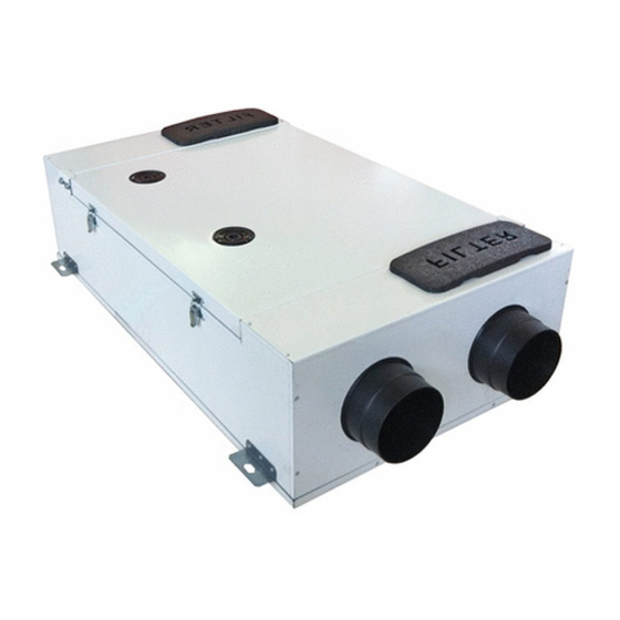
QR200A
Heat Recovery Ventilation Unit
Read this manual carefully before using the product and keep it in a safe
place for reference as necessary.
This product was constructed up to standard and in compliance with
regulations relating to electrical equipment and must be installed by technically qualified personnel.
The manufacturer assumes no responsibility for damage to persons or property resulting from failure to observe the instructions contained in this manual.
1 INDEX
1
2
2
2
3
3
3
4
4
4
4
4
5
6
7
8
8
9
10
11
13
16
17
17
17
18
18
20
1
Advertisement
Table of Contents

Related Manuals for aerauliqa QR200A


Summary of Contents for aerauliqa QR200A
-
Page 1: Table Of Contents
Installation Manual (installer & user) QR200A Heat Recovery Ventilation Unit Read this manual carefully before using the product and keep it in a safe place for reference as necessary. This product was constructed up to standard and in compliance with regulations relating to electrical equipment and must be installed by technically qualified personnel. -
Page 2: Precautions
The key to proper, safe and smooth operation of the unit is to read this manual thoroughly, use the unit according to given guidelines and follow all safety requirements. The QR200A is supplied with its CTRL-DSP remote multifunction control panel as standard. The package also includes 2 condensation elbows and 6 plugs for the water drainage. -
Page 3: Dimensions And Weight
3.2 Dimensions (mm) and Weight Weight Kg 3.3 Connections INTAKE EXTRACT EXHAUST SUPPLY Fig. 3.a Connections Intake air from outiside Exhaust air to outside filter side view Supply air to inside Extract air from inside Winter condensation drainage Summer condensation drainage EXHAUST SUPPLY EXTRACT... -
Page 4: Rating Label
3.5 Rating label Fig.3.b Rating label 4 traNsPort aND storagE WARNING Make sure that specific warnings and cautions in Chapter 2 “Precautions” are carefully read, understood and applied! The appliance is delivered in one carton box. The appliance should be stored and transported in such a way that it is protected against physical damage that can harm spigots, casing, display etc. It should be covered so that dust, rain and snow cannot enter and damage the unit and its components. -
Page 5: Ceiling Installation
5.3 Ceiling installation The unit must be installed in the following position. It is important that the unit is completely flat in order for the condensation drainage to work properly. holes to be closed SPIRIT LEVEL Fig 5.a Fig. 5.b SPIRIT LEVEL H=min. -
Page 6: Floor Installation
5.4 Floor installation The unit must be installed in the following position. It is important that the unit is completely flat in order for the condensation drainage to work properly. holes to be closed Fig 5.a Fig. 5.b H=min. 60mm Fig. -
Page 7: Electric Connections
The installation and service of the unit and complete ventilation system must be performed by an authorized installer and in accordance with local rules and regulations. The unit must be earthed. The QR200A is wired internally from factory. Figures below show the wiring diagram. CTRL-DSP... -
Page 8: Commissioning
6 commIssIoNINg 6.1 Setting Fan speed The speed of the unit can be adjusted during installation according to required ventilation rate. Figure 6.a below shows performance curves (for supply air and extract air) at different settings of the 0-10V signal to the motors. Airflow and consumption refer to one single motor. -
Page 9: Before Starting The System
Table 6.c Sound level Lp dB(A) Lw dB - SOUND POWER OCTAVE BAND 100% Intake Supply Extract Exhaust Breakout Lp dB(A) Lw dB - SOUND POWER OCTAVE BAND Intake Supply Extract Exhaust Breakout Lp dB(A) Lw dB - SOUND POWER OCTAVE BAND Intake Supply Extract... -
Page 10: Operation
7 oPEratIoN WARNING Make sure that specific warnings and cautions in Chapter 2 “Precautions” are carefully read, understood and applied! INTAKE EXTRACT EXHAUST SUPPLY Fig. 7.a Temperature probes Intake air from outiside Exhaust air to outside Supply air to inside Extract air from inside Fig. -
Page 11: User Menu On Ctrl-Dsp
When powered on, the CTRL-DSP displays as follows: Fig. 7.c CTRL-DSP operation screen 7.1 User Menu on CTRL-DSP To enter the user menu press OK or ESC. To exit the user menu press ESC or wait for about 60 seconds. User menu 1 Mode Selection 2 Boost... - Page 12 It allows to select the Boost speed. User menu Press OK to select. 1 Mode Selection Choice NO or YES using or . 2 Boost Press OK to select. Boost speed can be selected only if the Mode selection is 3V or HOLIDAY. 3 Boost Duration Boost function can be activated in these ways: 4 Reset FILTER Alarm...
-
Page 13: Installer Menu On Ctrl-Dsp
Press ESC to go back to the previous menu. 3 Bypass 4 Bypass settings 5 Free Cooling The factory setting (DEFAULT) is NO because the QR200A is not equipped with any Installer menu integral physical bypass. 1 Language 2 Date/Time... - Page 14 It allows to set the Bypass/Free Cooling operation parameters Installer menu Press OK to enter. 1 Language Use or to choose “Desired Temperature”, “Tmax Free Heating”, “Tmin Free Cooling” 2 Date/Time For definitions see “Free Cooling”, paragraph 7.3. Press OK to select.
- Page 15 To be selected only in case an external dehumidifier (not supplied) is present. Installer menu Press OK to enter. 6 Heating Use or to choose NO or YES. 7 Heating Threshold The factory setting (DEFAULT) is NO. 8 Dehumidification The DH relay output is activated when the HY input is activated (Fig.5.f) and the icon is displayed.
- Page 16 The system keeps trace of the actual working hours of the unit. This value cannot be changed. Data is Installer menu saved both on the motherboard and on the control panel CTRL-DSP, to be safe in case of fault. 11 F7 filter Press OK to enter.
-
Page 17: Additional Functionalities
7.3 Additional functionalities SLAVE MODE In case the SLAVE jumper (Fig.5.f - JP2) is short-circuited before powering the unit, the unit works in SLAVE MODE; the operating speed is determined by the 1-10V signal received at the SLAVE input. All the operating logics described in the Mode selection are ignored (paragraph 7.1). FREE COOLING The parameters “Desired Temperature”, “Tmax Free Heating”, “Tmin Free Cooling”... -
Page 18: Maintenance
8.2 Description of Components Fans The fans have external rotor motors of EC type which can be steplessly controlled individually between 10–100%. The motor bearings are life time lubricated and maintenance free. It is possible to easily disconnect and replace the fans if necessary. Filters The filters are of filter quality G4 for both the supply air and extract air filter. -
Page 19: Service
8.4 Service WARNING Make sure that the mains supply to the unit is disconnected before performing any installation, service, maintenance or electrical work! WARNING The installation and service of the unit and complete ventilation system must be performed by an authorized installer and in accordance with local rules and regulations. -
Page 20: Trouble Shooting
Fig. 8.n Fig. 8.o 8.5 Trouble shooting Fans do not start 1. Check that main supply gets to the unit. 2. Check that all connections are working (all connections in terminal box and fast couplings of intake and exhaust air fans). Reduced airflow 1. - Page 21 ErP Directive - regulations 1253/2014 - 1254/2014 AERAULIQA a) Marchio - Mark - Marque - Warenzeichen - Marca QR200A b) Modello - Model - Modèle - Modellkennung - Modelo c) Classe SEC - SEC class - classe de SEC - SEV-Klasse - clase CEE...
- Page 22 Instrucciones para la instalación de rejillas reguladas Indirizzo Internet istruzioni di preassemblaggio/ disassemblaggio Internet address for preassembly/disassembly instructions Adresse internet concernant les instructions de www.aerauliqa.com préassemblage/démontage Internetanschrift für Anweisungen zur Vormontage/ Zerlegung Dirección de internet para las instrucciones de montaje y desmontaje Sensibilità...
- Page 23 NOTE...
- Page 24 Sede operativa/Warehouse-Offices: via Mario Calderara 39/41, 25018 Montichiari (Bs) - Sede legale/Registered office: via Corsica 10, 25125 Brescia C.F. e P.IVA/VAT 03369930981 - REA BS-528635 - Tel: +39 030 674681 - Fax: +39 030 6872149 - www.aerauliqa.it - info@aerauliqa.it AERAULIqA SRL reserves the right to modify/make improvements to products and/or this instruction manual at any time and without prior notice.
Need help?
Do you have a question about the QR200A and is the answer not in the manual?
Questions and answers