Table of Contents
Advertisement
Quick Links
G
Installation Manual (installer & user)
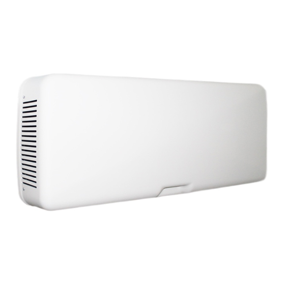
QR100M
Heat Recovery Ventilation Unit
Read this manual carefully before using the product and keep it in a safe place for reference as necessary.
This product was constructed up to standard and in compliance with regulations relating to electrical equipment
and must be installed by technically qualified personnel.
The manufacturer assumes no responsibility for damage to persons or property resulting from failure to observe the instructions contained in this manual.
1 INDEX
1
2
2
2
3
3
3
4
4
4
4
4
5
6
8
8
9
9
9
9
9
9
9
9
9
10
10
10
11
12
13
1
Advertisement
Table of Contents

Related Manuals for aerauliqa QR100M


Summary of Contents for aerauliqa QR100M
-
Page 1: Table Of Contents
Installation Manual (installer & user) QR100M Heat Recovery Ventilation Unit Read this manual carefully before using the product and keep it in a safe place for reference as necessary. This product was constructed up to standard and in compliance with regulations relating to electrical equipment and must be installed by technically qualified personnel. -
Page 2: Precautions
The key to proper, safe and smooth operation of the unit is to read this manual thoroughly, use the unit according to given guidelines and follow all safety requirements. The QR100M is supplied with 2 condensation elbows, 1 plug, 2xØ98mm spigots for air intake and exhaust and 1 installation template. -
Page 3: Dimensions And Weight
3.2 Dimensions (mm) and Weight Fig. 3.a Weight Kg 12,5 3.3 Connections Fig. 3.b Connections Intake air from outiside Exhaust air to outside Supply air to inside Extract air from inside Winter condensation drainage Summer condensation drainage 3.4 Space required Make sure that enough space is left around the unit to allow easy maintenance (removal of the front cover for access to filters and terminal box). -
Page 4: Transport And Storage
4 traNsPort aND storagE WARNING Make sure that specific warnings and cautions in Chapter 2 “Precautions” are carefully read, understood and applied! The appliance is delivered in one carton box. The appliance should be stored and transported in such a way that it is protected against physical damage that can harm spigots, casing etc. It should be covered so that dust, rain and snow cannot enter and damage the unit and its components. -
Page 5: Installation
5.3 Installation The unit must be installed in the following position. It is important that the unit is completely flat in order for the condensation drainage to work properly. Fig. 5.a,b,c Fig. 5.d Fig. 5.e Fig. 5.f Fig. 5.g Spirit level H=min. -
Page 6: Electric Connections
The installation and service of the unit and complete ventilation system must be performed by an authorized installer and in accordance with local rules and regulations. The unit must be earthed. The QR100M is wired internally from factory. Figures below show the wiring diagrams. CTrL-S... - Page 7 Dip switch operation Single speed Two speed Variable speed with CTRL-M remote manual controller Variable speed throught external domotic (BMS) system or ballast potentiometer Three speed with SEL-3V Three speed with CTRL-S 1 2 3 Fig. 5.r CTRL-M Fig. 5.s SEL-3V Fig.
-
Page 8: Commissioning
6 commIssIoNINg 6.1 Setting Fan speed The speed of the unit can be adjusted during installation according to required ventilation rate. Figure 6.a below shows performance curves (for supply air and extract air) at different settings of the 0-10V signal to the motors. Airflow and consumption refer to the 2 motors. -
Page 9: Before Starting The System
6.2 Before Starting the System When the installation is finished , check that: • Filters are mounted correctly • The unit is installed in accordance with the instructions • The unit is correctly wired • Outdoor air intake is positioned with sufficient distance to pollution sources (kitchen ventilator exhaust, central vacuum system exhaust or similar) •... -
Page 10: Maintenance And Service
8 maINtENaNcE aND sErvIcE WARNING Make sure that specific warnings and cautions in Chapter 2 “Precautions” are carefully read, understood and applied! Maintenance can be carried out by the user. Service must be performed only by an authorized installer and in accordance with local rules and regulations . Questions regarding installation, use, maintenance and service of the unit should be answered by your installer or place of purchase! 8.1 Components list FILTER G4, ExTRACT AIR... -
Page 11: Maintenance
8.3 Maintenance WARNING Make sure that the mains supply to the unit is disconnected before performing any installation, service, maintenance or electrical work! • Keep the unit surface free from dust. • Clean the filters every three months with a vacuum cleaner and replace the filters every year. This may differ per situation depending on internal and external environmental conditions (fig.8 b-c-d-e-f). -
Page 12: Service
8.4 Service WARNING Make sure that the mains supply to the unit is disconnected before performing any installation, service, maintenance or electrical work! WARNING The installation and service of the unit and complete ventilation system must be performed by an authorized installer and in accordance with local rules and regulations. -
Page 13: Trouble Shooting
Fig. 8.o Fig. 8.p Fig. 8.q Fig. 8.r 8.5 Trouble shooting Fans do not start 1. Check that main supply gets to the unit. 2. Check that all connections are working (all connections in terminal box and fast couplings of supply and extract air fans). 3. - Page 14 ErP Directive - regulations 1253/2014 - 1254/2014 AERAULIQA a) Marchio - Mark - Marque - Warenzeichen - Marca QR100M b) Modello - Model - Modèle - Modellkennung - Modelo c) Classe SEC - SEC class - classe de SEC - SEV-Klasse - clase CEE...
- Page 15 Indirizzo Internet istruzioni di preassemblaggio/ disassemblaggio Internet address for preassembly/disassembly instructions Adresse internet concernant les instructions de www.aerauliqa.com préassemblage/démontage Internetanschrift für Anweisungen zur Vormontage/Zerlegung Dirección de internet para las instrucciones de montaje y desmontaje Sensibilità...
- Page 16 C.F. e P.IVA/VAT 03369930981 - REA BS-528635 - Tel: +39 030 674681 - Fax: +39 030 6872149 - www.aerauliqa.it - info@aerauliqa.it Aerauliqa srl si riserva il diritto di modificare/apportare migliorie ai prodotti e/o alle istruzioni di questo manuale in qualsiasi momento e senza preavviso.
Need help?
Do you have a question about the QR100M and is the answer not in the manual?
Questions and answers