
Related Manuals for Phoenix Contact ILC 2050 BI


Summary of Contents for Phoenix Contact ILC 2050 BI
- Page 1 Installing and operating the ILC 2050 BI and ILC 2050 BI-L Inline controllers User manual UM EN ILC 2050 BI...
- Page 2 UM EN ILC 2050 BI, revision 01 2019-01-09 This user manual is valid for: Designation Revision Order No. ILC 2050 BI 2403160 ILC 2050 BI-L 2404671 PHOENIX CONTACT GmbH & Co. KG • Flachsmarktstraße 8 • 32825 Blomberg • Germany phoenixcontact.com...
-
Page 3: Table Of Contents
Internal basic circuit diagram ................13 Interfaces......................14 2.6.1 Ethernet ....................14 2.6.2 Serial interfaces ................... 15 2.6.3 LON (ILC 2050 BI-L only) ..............16 2.6.4 USB ..................... 16 2.6.5 Inline local bus interface ............... 17 Software ......................18 2.7.1 System shell .................. - Page 4 Remote control of the Inline terminals ..........53 Concurrent access to the Inline terminals ............54 Technical data and ordering data .....................56 Technical data ..................... 56 Ordering data ILC 2050 BI(-L) ................59 Technical appendix........................60 Fault avoidance ....................60 Diagnostics......................62 Fault causes and remedies..................
-
Page 5: Foreword
Foreword Purpose of this user manual This user manual will help you to start up and operate the Inline controller ILC 2050 BI (Or- der No. 2403160) and ILC 2050 BI-L (Order No. 2404671). Hereinafter, this document uses the general term Inline controller. -
Page 6: Intended Use
Phoenix Contact GmbH & Co. KG, Flachsmarktstraße 8, 32825 Blomberg, Germa- ny, in accordance with §§ 15 ff. AktG or the German Stock Corporation Act (hereinafter collectively referred to as “Phoenix Contact”) from all third-party claims made due to im- proper use. -
Page 7: Description Of The Inline Controller
Description of the Inline controller General description of the Inline controller The ILC 2050 BI and ILC 2050 BI-L controllers look exactly the same, differing in just a few details and functions. Hereinafter, therefore, this document uses the general terms controller, bus controller, Inline controller, or ILC 2050 BI (-L). -
Page 8: Connection And Operating Elements
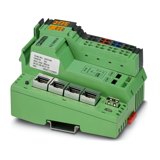
Micro SD card slot The micro SD card is not supplied as standard with the Inline controller. Please refer to the ordering data in Section “Ordering data ILC 2050 BI(-L)” on page Imprint of the device-specific information Service button Ethernet interfaces (4 x 10/100Base-T) -
Page 9: Assignment Of Dip Switches For Rs-485 Termination
COM1 or COM2 according to BACnet MS/TP specifications. Each in- dividual resistor can therefore be separately switched on via DIP switch. RS-485 Termination Bias RS-485 RS-485 107144A013 Figure 2-2 Assignment of DIP switches for RS-485 termination 9 / 74 107144_en_01 PHOENIX CONTACT... -
Page 10: Diagnostic And Status Indicators
ILC 2050 BI Diagnostic and status indicators SERVICE ST UM PL US 1.1 2.1 1.1 2.1 SE UL 1.2 2.2 1.2 2.2 1.3 2.3 1.3 2.3 USB 1 USB 2 1.4 2.4 1.4 2.4 107144A010 Figure 2-3 Diagnostic and status indicators... - Page 11 Data is being received via COM2. COM2 Tx Yellow Data is being sent via COM2. LON Tx Data is being sent via LON. Yellow (ILC 2050 BI-L only) LON Rx Data is being received via LON. Green (ILC 2050 BI-L only) 11 / 74 107144_en_01...
- Page 12 ILC 2050 BI Table 2-1 Diagnostic and status indicators [...] Des. Color Status Meaning Service LED Normal operation and for approx. 7 s after applying the supply voltage Inline controller boots; SV LED lights up for approx. 7 s SV LED flashes after booting for approximately 2 s,...
-
Page 13: Internal Basic Circuit Diagram
Internal basic circuit diagram Key: Ethernet switch Microprocessor Optocoupler Converter Inputs/outputs, shown as RS-485 driver (generator/receiver) Transmitter Electrically isolated areas Other symbols used are explained in the IL SYS INST UM E user manual. 13 / 74 107144_en_01 PHOENIX CONTACT... -
Page 14: Interfaces
ILC 2050 BI Interfaces 2.6.1 Ethernet The integrated Ethernet switch has four external Ethernet interfaces, which can optionally be assigned to the two independent IP interfaces of the processor. In the delivery state, eth0 is connected to LAN 3 and LAN 4, and eth1 is connected to LAN 1 and LAN 2. -
Page 15: Serial Interfaces
COM1 RS-485 data signal + (positive) COM1 - COM1 RS-485 data signal - (negative) COM1 shield connection LON TP/FT-10 polarity-independent (ILC 2050 BI-L only) COM2 + COM2 RS-485 data signal + (positive) COM2 - COM2 RS-485 data signal - (negative) -
Page 16: Lon (Ilc 2050 Bi-L Only)
Section “Serial interfaces” on page 51). 2.6.3 LON (ILC 2050 BI-L only) The Inline controller (ILC 2050 BI-L only) has one LON interface in accordance with the CEA-709 standard for connecting to LON TP/FT-10 networks directly (Figure 2-12). Ensure compliance with LonMark wiring guidelines (www.lonmark.org) when connecting devices featuring LonWorks technology. -
Page 17: Inline Local Bus Interface
The Inline local bus interface enables up to 63 Inline terminals to be connected. It consists of the communication channel to the Inline terminals and the power supply to the Inline ter- minals as well as the connected sensors and actuators. 17 / 74 107144_en_01 PHOENIX CONTACT... -
Page 18: Software
ILC 2050 BI Software A Linux operating system runs on the Inline controller, where multiple applications are exe- cuted in parallel. Niagara - Eco - Syste m Browser Workbench Supervisor (local installation) (engineering) (integration) BACnet Installation Niagara Niagara Modbus Website... -
Page 19: Startup Website
Data point integration via a variety of (open) protocols (LON, BACnet, KNX, Modbus, and others) with data standardization – System functions (time switch, alarms, trend recording) – Web visualization – Enterprise interfaces (oBIX, databases) – Inline controller dimensions 107144A003 Figure 2-9 Inline controller dimensions 19 / 74 107144_en_01 PHOENIX CONTACT... -
Page 20: Mounting And Removing The Inline Controller
Mount end brackets on both sides of the Inline station. The end brackets ensure that the In- line station is correctly mounted. They secure the Inline station on both sides and keep it from moving from side to side on the DIN rail. Phoenix Contact recommends using CLIPFIX 35-5 end brackets (Order No. 3022276). - Page 21 2-11, A). Then push the connector toward the electronic base until it engages in the rear latching mechanism (Figure 2-11, B). Figure 2-10 Mounting the Inline controller (1) Figure 2-11 Mounting the Inline controller (2) 21 / 74 107144_en_01 PHOENIX CONTACT...
-
Page 22: Connectors To Be Removed When Inline Terminals Are Attached
ILC 2050 BI Removal When removing the Inline controller from the DIN rail, proceed as shown in Figure 2-13: • Disconnect the Inline station from the power supply. NOTE: Risk of damage during mounting and removal if an Inline terminal is left in position When mounting or removing the Inline controller, it must be tilted. -
Page 23: Removing The Inline Controller (1)
Take special care to ensure that all the springs and slots of adjacent Inline terminals in- terlock properly. Observe the following when replacing an Inline controller: • If you are using the BootP server, enter the new MAC address. 23 / 74 107144_en_01 PHOENIX CONTACT... -
Page 24: Power Supply
ILC 2050 BI 2.10 Power supply The Inline controller is operated using a 24 V DC voltage. From this 24 V DC, the Inline con- troller generates the logic voltage for the logic circuit and the analog voltage for the analog circuit. - Page 25 DIN rail. The functional ground serves to discharge interference. The functional ground connection (terminal points 1.4 and 2.4) must also be connected to the DIN rail using a 1.5 mm conductor and a grounding terminal (see Figure 2-16). 25 / 74 107144_en_01 PHOENIX CONTACT...
-
Page 26: Connection Assignment Of The Feed-In Terminal
ILC 2050 BI I L C 107144A006 Figure 2-16 Schematic view of functional ground of the Inline controller Table 2-3 Connection assignment of the feed-in terminal Terminal Designation Function point 24 V DC segment supply (segment circuit) The fed-in voltage is routed to the Inline terminals via the potential jumpers. -
Page 27: Calculating The Power Dissipation
USB stick in the USB 2 interface with 0.1 A current consumption. = 4.1 W + 0.7 V x 0.1 A + 1.0 V x 2.0 A = 4.1 W + 0.07 W + 2.0 W = 6.17 W 27 / 74 107144_en_01 PHOENIX CONTACT... -
Page 28: Calculating The Current Consumption Of An Inline Station
ILC 2050 BI 2.10.2 Calculating the current consumption of an Inline station For power supply unit dimensioning, you must determine the current consumption of the en- tire Inline station. It is calculated using: = Current consumption of the entire Inline station... -
Page 29: Safety Equipment, 24 V Segment Supply And 24 V Main Supply
Each 24 V area must be protected externally. The power supply unit must be able to sup- ply four times the nominal current of the external fuse; this is to ensure that it trips the fuse in the event of an error. 29 / 74 107144_en_01 PHOENIX CONTACT... -
Page 30: Software For Configuring The Inline Controller
ILC 2050 BI Software for configuring the Inline controller General information on software A Linux operating system runs on the Inline controller, where multiple applications are exe- cuted in parallel. The Inline controller is configured and programmed via the Niagara Work- bench. -
Page 31: Configuration Tools
Various protocols and services for configuration, startup, and diagnostics are available for the PC via the USB OTG connection,. Table 3-2 Protocols via USB OTG Protocol Port PC software Application Telnet Telnet client System shell HTTP 8080 Web browser Startup website 31 / 74 107144_en_01 PHOENIX CONTACT... -
Page 32: System Shell
ILC 2050 BI 3.2.2 System shell You can apply basic settings to the Inline controller via the system shell. To apply settings via the system shell, proceed as follows: • Connect your PC to the Inline controller via USB OTG (see also Section “Mini USB in-... -
Page 33: System Shell (Example)
10. Reset Platform Credentials Resets the access data for the Niagara platform to the delivery state (user: “sysmik”, password: “intesa”, dae- mon HTTP port 3011, daemon HTTPS port 5011) 11. Reboot Restarts the Inline controller x. Exit Terminates the Telnet connection 33 / 74 107144_en_01 PHOENIX CONTACT... -
Page 34: Startup Website
ILC 2050 BI 3.2.3 Startup website The startup website enables you to make device settings and access data points of con- nected Inline terminals. To apply settings via the startup website, proceed as follows: • Connect your PC to the Inline controller via USB OTG (see also Section “Mini USB in-... -
Page 35: Startup Website: "Settings, Network
“Switch” for configuring the internal Ethernet switch “Settings, Network” On the “Settings, Network” page, you can change the connection parameters of the two Ethernet interfaces (Interface 1 and Interface 2 in Figure 3-4). Figure 3-4 Startup website: “Settings, Network” 35 / 74 107144_en_01 PHOENIX CONTACT... -
Page 36: Startup Website: "Settings, Webserver
ILC 2050 BI “Settings, Webserver” On the “Settings, Webserver” page, you can determine the HTTP port (default setting: 81) and activate or deactivate the temperature measurement in degrees Fahrenheit. Figure 3-5 Startup website: “Settings, Webserver” “Settings, Date/Time” On the “Settings, Date/Time” page, you can set the date, time, time zone, and IP address of the SNTP time server. -
Page 37: Startup Website: "Settings, Io Server
Inline controller, which is permitted to control the inputs and outputs of the Inline control- ler at hand. With the IP address “255.255.255.255”, every Inline controller can control inputs and outputs. Figure 3-7 Startup website: “Settings, IO Server” 37 / 74 107144_en_01 PHOENIX CONTACT... -
Page 38: Startup Website: "Settings, Run
ILC 2050 BI “Settings, Run” On the “Settings, Run” page, you can activate or deactivate Niagara and/or Sedona. Here you also have the option to carry out a reboot. Figure 3-8 Startup website: “Settings, Run” 38 / 74 PHOENIX CONTACT... -
Page 39: Startup Website: "Settings, Switch
On the “Settings, Switch” page, you can configure the internal Ethernet switch. This includes assigning the external Ethernet interfaces to the internal IP interfaces of the controller, acti- vating RSTP or ring monitoring, and setting the parameters for avoiding broadcast storms. Figure 3-9 Startup website: “Settings, Switch” 39 / 74 107144_en_01 PHOENIX CONTACT... -
Page 40: Startup Website: "Terminals
ILC 2050 BI 3.2.3.3 “Terminals” On the “Terminals” page, you can see all the connected Inline terminals. You can manually override the Inline terminals for data point tests (see Section “Hardware data point test” on page 43). Figure 3-10 Startup website: “Terminals”... -
Page 41: Sftp Server
There are several ways of configuring the IP address: – System shell (see Section “System shell” on page – Startup website via “Settings, Network” (see Section 3.2.3) – Niagara Workbench via platform connection to the Niagara Daemon under “TCP/IP Configuration” 41 / 74 107144_en_01 PHOENIX CONTACT... -
Page 42: Setting The Time Zone And Time
ILC 2050 BI 3.3.2 Setting the time zone and time The time is held in a buffered real-time clock (RTC). On delivery, the buffer capacitor is gen- erally discharged. The clock begins to count when the Inline controller is first started up, showing 01.01.2000, 0:00. -
Page 43: Hardware Data Point Test
Thus, a data point test is possi- ble, even without application software. When logging out of the startup website (manually or following timeout), all overrides are automatically canceled. Figure 3-11 Data point test via the startup website 43 / 74 107144_en_01 PHOENIX CONTACT... -
Page 44: Ethernet Switch For Flexible Network Topologies
ILC 2050 BI Ethernet switch for flexible network topologies The integrated Ethernet switch with four external and two internal Ethernet interfaces facili- tates Ethernet cabling without additional switches. It supports: – The optional assignment of IP interfaces to external Ethernet interfaces –... -
Page 45: Lan 3
Ethernet interface. Direct communication is possible between the Ether- net interfaces, so several devices can be interconnected in a line topology, see Figure 3-12. Ethernet communication is not possible between Ethernet interfaces belonging to different IP interfaces. 45 / 74 107144_en_01 PHOENIX CONTACT... -
Page 46: Ethernet Ring Monitoring
ILC 2050 BI Lorem ipsum SERVICE ST UM 1. 1 2 .1 1. 1 2 .1 1. 2 2 .2 1. 2 2 .2 1. 3 2 .3 1. 3 2 .3 USB 1 USB 2 1. 4 2 .4 1. -
Page 47: Rapid Spanning Tree Protocol (Rstp)
LAN 2 ... 4 at eth0, LAN 1 at eth1 RSTP configuration Table 3-9 LAN 3 ... 4 at eth0, LAN 1 ... 2 at eth1 (delivery state) RSTP configuration Table 3-10 LAN 4 at eth0, LAN1 ... 3 at eth1 RSTP configuration 47 / 74 107144_en_01 PHOENIX CONTACT... -
Page 48: Interface Status Information
ILC 2050 BI 3.4.4 Interface status information If ring monitoring or RSTP is activated, the status of the external Ethernet interfaces is shown in the Niagara application, in the Sedona application, and on the startup website for analysis purposes. This enables redundancy to be monitored in network topologies. -
Page 49: Integration With The Niagara Framework
Inline controller: – BACnet IP – BACnet MS/TP (only on COM1 and COM2) – LonWorks IP852 – LonMark TP/FT-10 (ILC 2050 BI-L only) – Modbus/TCP – Modbus/RTU, M-Bus – KNX/IP – SNMP –... - Page 50 ILC 2050 BI “N Point Manager” In “N Point Manager”, the standard view of the point folder of the terminal components, you can display the I/O channels available via “Discover”. You can add the available I/O chan- nels into the application as proxy points using “Add”. Some data points have special func- tions: –...
-
Page 51: Serial Interfaces
The interface names of the Inline terminals are issued according to their installation order, beginning with COM3. A summary of all serial interfaces, including their current use (“Owner”) is available under “Station, Config, Services, PlatformServices, SerialPortPlat- formServiceNpsdk”. 51 / 74 107144_en_01 PHOENIX CONTACT... - Page 52 ILC 2050 BI Example Figure 3-15 shows this overview for an Inline controller with a total of four serial interfaces – the two serial interfaces of the Inline controller and two further serial interfaces, which were added via Inline terminals: –...
-
Page 53: Remote Control Of The Inline Terminals
Enter an invalid IP address (empty string) to deactivate remote control. Further- more, via “Station, Config, Drivers, SysMikScaIoNetwork, localPlatform, IoPort”, you can specify the TCP port number of the I/O server. Figure 3-18 Parameterization of the I/O server 53 / 74 107144_en_01 PHOENIX CONTACT... -
Page 54: Concurrent Access To The Inline Terminals
ILC 2050 BI Concurrent access to the Inline terminals As already explained, multiple software components of the Inline controller can control the Inline terminals of the Inline system. For reading input data, this does not pose a problem. For output data and parameterizations, however, the software components can work against each other. - Page 55 Initialization of count values of the counter terminal – DALI light control commands – Initialization, reading, and writing functions for the Inline terminals Program your application so it cannot be accessed inadvertently through several sourc- 55 / 74 107144_en_01 PHOENIX CONTACT...
-
Page 56: Technical Data And Ordering Data
1.5 mm Single-wire/terminal point, flexible 0.08 mm to 1.5 mm Single-wire/terminal point, AWG 28 to 16 Phoenix Contact recommends using conductors with a con- ductor cross section of 0.2 mm to 1.5 mm Processor core ® ® Processor / clock... - Page 57 24 V analog voltage loaded with 0.5 A without USB devices Separation of functions! The isolation is bridged for interference elimination with a 300 V varistor and does not fulfil the safety regulations for protec- tion against dangerous shock voltages. 57 / 74 107144_en_01 PHOENIX CONTACT...
- Page 58 ILC 2050 BI Ambient conditions Degree of protection IP20 (EN 60529:1991) Ambient temperature (operation) -25°C ... +55°C Permissible temperature (storage/transport) -25°C ... +85°C Temperature class This temperature range is only guaranteed if the Inline controller is mounted horizontally. Permissible humidity (operation/storage/transport) 0% …...
-
Page 59: Ordering Data Ilc 2050 Bi(-L)
Test voltage 10 V Noise emission test in accordance with EN 61000-6-3 (residential and commercial spaces) Noise emissions EN 55022 Class B Ordering data ILC 2050 BI(-L) Description Type Order No. Pcs./Pkt. The modular Inline controller for automation applications in... -
Page 60: A Technical Appendix
63 DALI terminals, if the DALI buses are being utilized at a higher level, no more than eight DALI terminals should be connected to an Inline controller. When using DALI sensors in particular, the desired response time is a crucial factor. 60 / 74 107144_en_01 PHOENIX CONTACT... - Page 61 With regard to the ambient temperature, the maximum values specified in Section “Techni- cal data” on page 56, taking the mounting position into account (see Section “Mounting and removing the Inline controller” on page 20), should never be exceeded. 61 / 74 107144_en_01 PHOENIX CONTACT...
-
Page 62: A 2 Diagnostics
ILC 2050 BI Diagnostics The most frequent faults arise in conjunction with other devices or components. Therefore, when a fault occurs the Inline controller should not be isolated straightaway; instead, it should be viewed as part of the system as a whole. -
Page 63: A 3 Fault Causes And Remedies
8) to reset the access data to the default settings (user: “sysmik”, password: “intesa”). • Restart the Inline controller and press the ser- vice button at exactly the right time (see Table 2-1 on page 10). 63 / 74 107144_en_01 PHOENIX CONTACT... - Page 64 ILC 2050 BI Table A-1 Fault causes and remedies Fault Cause Remedy Duplicate usage of the daemon HTTP • Use the system shell (see Section “System port: shell” on page 32) or the startup website (see Section “Startup website” on page...
-
Page 65: A 4 Derating
2 A. Then the current load on the USB slots may amount to a max- imum of 0.5 A: = (0.87 x P - 1 V x I ) / 0.7 V = (2.35 W - 2 W) / 0.7 V = 0.5 A 65 / 74 107144_en_01 PHOENIX CONTACT... - Page 66 ILC 2050 BI Example 2: Given an ambient temperature of 45°C and a non-horizontal mounting position, a USB de- Different mounting posi- vice also needs to be supplied with 200 mA. The power supply unit dissipation may amount tion to 70% in this case, i.e., 1.89 W. For the maximum current from U this results in: = (0.7 x P...
-
Page 67: B Appendix For Document Lists
Figure 3-8: Startup website: “Settings, Run” ............38 Figure 3-9: Startup website: “Settings, Switch” ............. 39 Figure 3-10: Startup website: “Terminals” ............... 40 Figure 3-11: Data point test via the startup website ..........43 67 / 74 107144_en_01 PHOENIX CONTACT... - Page 68 ILC 2050 BI Figure 3-12: Example of Ethernet cabling ............... 46 Figure 3-13: “N Device Manager” in the “SysMikScaIoNetwork” ......49 Figure 3-14: “N Point Manager” of a terminal component ........50 Figure 3-15: SerialPortPlatformServiceNpsdk ............52 Figure 3-16: IB IL RS UNI-PAC interface parameterization ........52...
-
Page 69: B 2 List Of Tables
LAN 4 at eth0, LAN1 ... 3 at eth1 ............47 Table 3-11: Release values of priority control ............54 Table 3-12: Hierarchy of priority control..............54 Table 3-13: Default values of priority control............55 Appendix A Table A-1: Fault causes and remedies..............63 69 / 74 107144_en_01 PHOENIX CONTACT... - Page 70 ILC 2050 BI 70 / 74 PHOENIX CONTACT 107144_en_01...
-
Page 71: B 3 Index
Unauthorized access ..........31 LON ................16 LonMark..............16 Mini USB ............... 16 USB OTG ............16, 31 USB type A............17 Mounting ..............21 Mounting location............20 Mounting position............20 Operating elements............8 71 / 74 107144_en_01 PHOENIX CONTACT... - Page 72 ILC 2050 BI 72 / 74 PHOENIX CONTACT 107144_en_01...
- Page 73 The receipt of technical documentation (in particular user documentation) does not constitute any further duty on the part of Phoenix Contact to furnish information on modifications to products and/or technical documentation. You are responsible to verify the suitability and intended use of the products in your specific application, in particular with regard to observing the applicable standards and regulations.
- Page 74 Should you have any suggestions or recommendations for improvement of the contents and layout of our manuals, please send your comments to: tecdoc@phoenixcontact.com PHOENIX CONTACT GmbH & Co. KG • Flachsmarktstraße 8 • 32825 Blomberg • Germany 74 / 74 phoenixcontact.com...
- Page 76 PHOENIX CONTACT GmbH & Co. KG Flachsmarktstraße 8 32825 Blomberg, Germany Phone: +49 5235 3-00 Fax: +49 5235 3-41200 E-mail: info@phoenixcontact.com phoenixcontact.com...
Need help?
Do you have a question about the ILC 2050 BI and is the answer not in the manual?
Questions and answers