Table of Contents
Advertisement
Advertisement
Chapters
Table of Contents

Related Manuals for Phoenix Contact AXC F 1050


Summary of Contents for Phoenix Contact AXC F 1050
- Page 1 Installing, starting up, and operating the AXC F 1050 controller User manual...
- Page 2 UM EN AXC F 1050 2018-10-30 This user manual is valid for: Designation As of HW ver- As of FW version Order No. sion AXC F 1050 4.00 2404701 PHOENIX CONTACT GmbH & Co. KG • Flachsmarktstraße 8 • 32825 Blomberg • Germany phoenixcontact.com...
-
Page 3: Table Of Contents
Field of application of the product ................8 1.3.1 Intended use ..................8 1.3.2 Modifications ..................8 Safety notes......................8 Notes on using the AXC F 1050 controller in potentially explosive areas.....11 Transport and unpacking ......................13 Transport ......................13 Storage........................13 Checking the delivery ..................13 Unpacking ......................14 Description of the AXC F 1050 ....................15... - Page 4 AXC F 1050 Mounting hardware ........................35 Safety notes......................35 Basics........................37 Structure of an Axioline F station .................39 Mounting the controller ..................40 Inserting the SD card ...................41 Connecting and wiring hardware ....................42 Safety notes......................42 Supply voltage .....................44 5.2.1 Sizing of the power supply ..............44 5.2.2...
- Page 5 8.12 Project-related system variables................103 Web-based management (WBM) ..................104 Establishing a connection to the WBM ..............104 Changing the language..................104 Areas and functions ...................104 9.3.1 “Information” area ................105 9.3.2 “Diagnostics” area ................108 9.3.3 “Administration” area ................114 5 / 140 107709_en_00 PHOENIX CONTACT...
- Page 6 AXC F 1050 10 Removing hardware .......................120 10.1 Safety notes.......................120 10.2 Removing cables ....................121 10.3 Removing the plug.....................121 10.4 Removing the SD card..................122 10.5 Removing the controller..................122 11 After use ..........................123 11.1 Maintenance and servicing ................123 11.2 Device replacement...................123 11.3 Device failure and repair ..................124...
-
Page 7: For Your Safety
– Qualified application programmers and software engineers. The users must be familiar with the relevant safety concepts of automation technology as well as applicable stan- dards and other regulations. 7 / 140 107709_en_00 PHOENIX CONTACT... -
Page 8: Field Of Application Of The Product
1.3.1 Intended use The AXC F 1050 controller is a modular small-scale controller that can be used for smaller and medium-sized applications. The device has an IP20 protection class and is designed for use in closed control cabinets or control boxes (junction boxes) with IP54 degree of pro- tection or higher. - Page 9 Phoenix Contact GmbH & Co. KG, Flachsmarktstraße 8, 32825 Blomberg in accor- dance with §§ 15 ff. AktG or the German Stock Corporation Act (hereinafter collectively referred to as “Phoenix Contact”) from all third-party claims that are made due to improper use.
- Page 10 AXC F 1050 NOTE: Device failure if operated outside the permitted ambient temperature range Operating the device in ambient temperatures that are not within the permitted range may lead to malfunctions or even device failure. • Ensure that the device is being operated within the permitted ambient temperature range, see Section 12.1 for more information.
-
Page 11: Notes On Using The Axc F 1050 Controller In Potentially Explosive Areas
For your safety Notes on using the AXC F 1050 controller in potentially explosive areas Approval in accordance with the 2014/34/EU directive II 3 G Ex nA IIC T4 Gc X WARNING: Explosion hazard Please make sure that the following notes and instructions are observed! - Page 12 AXC F 1050 Installation in zone 2 Observe the specified conditions for use in potentially explosive areas. Install the device in a suitable approved housing (with at least IP54 protection in accor- dance with EN 60529) that meets the requirements of EN 60079-15:2010. Pay atten- tion to the requirements of EN 60079-14.
-
Page 13: Transport And Unpacking
Damaged packaging is an indicator of potential damage to the device that may have oc- curred during transportation. This could result in a malfunction. • Submit claims for any transport damage immediately, and inform Phoenix Contact or your supplier as well as the shipping company without delay. •... -
Page 14: Unpacking
AXL BS BK bus base module – AXL CN S/UL supply plug Unpacking The AXC F 1050 is supplied in the packaging together with a packing slip with installation instructions. • Read the complete packing slip carefully before unpacking the controller. -
Page 15: Description Of The Axc F 1050
PC Worx Engineer ≥ 7.2.2 General description of the controller The AXC F 1050 controller is approved for use in Zone 2 potentially explosive areas. • Observe the notes in Section “Notes on using the AXC F 1050 controller in potentially explosive areas”... - Page 16 It cannot be used as a PROFINET controller and device con- currently. For additional information on how to integrate the AXC F 1050 as a PROFINET controller or device, please see Section 7.4. Axioline F local bus An interface to the Axioline F local bus is provided on the bottom of the controller.
- Page 17 Description of the AXC F 1050 Visualization You can create visualizations for the controller using the PC Worx Engineer HMI. Real-time clock In the event that the supply voltage fails, the real-time clock integrated in the controller is buffered (see Section “Technical data” on page 125). You can query the status of the real- time clock using system variables (see Section 8.9 for more information).
-
Page 18: Possible Fields Of Application Of The Controller
The total current consumption of all devices aligned on the con- troller must not exceed the maximum current that the controller supplies for the local bus (2 A). Ethernet 42 43 02 03 8482B001 Figure 3-2 Axioline F station with AXC F 1050 controller 18 / 140 PHOENIX CONTACT 107709_en_00... -
Page 19: The Axc F 1050 As A Profinet Controller In A Profinet Network
Description of the AXC F 1050 3.3.2 The AXC F 1050 as a PROFINET controller in a PROFINET network Figure 3-3 shows the example of an AXC F 1050 as a PROFINET controller in a PROFINET network. PROFINET PROFINET 8482A020... -
Page 20: The Axc F 1050 As A Profinet Device In A Profinet Net- Work
AXC F 1050 3.3.3 The AXC F 1050 as a PROFINET device in a PROFINET net- work Figure 3-4 shows the example of an AXC F 1050 as a PROFINET device in a PROFINET network. RUN/PROG DISPLAY MRESET RFC 470 PN 3TX LAN1.1... -
Page 21: System Redundancy With The Axc F 1050
PROFINET ring network that is configured as redundant using the Media Redundancy Protocol (MRP). In the example, the AXC F 1050 controller oper- ates as a PROFINET device with control function and is connected to the PROFINET net- work via a switch. - Page 22 (BACKUP/PRIMARY) may change depending on the redundancy status Infrastructure components (in the example: FL SWITCH SMCS ... managed switches) PROFINET device with control function (in the example: AXC F 1050 with activated PROFINET device function and Phoenix Redundancy Layer) 22 / 140...
-
Page 23: Connection And Operating Elements
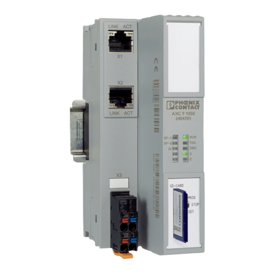
Description of the AXC F 1050 Connection and operating elements Figure 3-6 Connection and operating elements of the controller Bus base module Reset button Service interface (Micro-USB type B), not currently used Electronics module Ethernet interfaces Function identification Supply socket (socket for connecting the supply voltage (communications power U SD card holder The SD card is not included in the scope of delivery of the controller. -
Page 24: Diagnostics And Status Indicators
Status Description nation PN: PROFINET controller/device function AXC F 1050 as a PROFINET controller – The AXC F 1050 has established an active communication connection to each configured PROFINET device. PROFINET con- troller: BF-C – The PROFINET controller function is switched off. - Page 25 Description of the AXC F 1050 Table 3-1 Controller diagnostics and status indicators Desig- Color Meaning Status Description nation PLC: Controller diagnostics IEC 61131 runtime system is not operational. IEC 61131 runtime system successfully initialized and an appli- cation program is running.
- Page 26 AXC F 1050 Table 3-1 Controller diagnostics and status indicators Desig- Color Meaning Status Description nation AXC: Axioline F diagnostics Power down: Device is in (power) reset Run: The Axioline F station is ready for operation; communication On green within the Axioline F station is OK.
- Page 27 Description of the AXC F 1050 Table 3-1 Controller diagnostics and status indicators Desig- Color Meaning Status Description nation ETH: Ethernet interfaces Connection not established successfully Connection established successfully (link): the controller is Green Link status able to contact another network device.
-
Page 28: Mode Selector Switch
AXC F 1050 Mode selector switch The mode selector switch is used to define the operating state of the controller. The RUN/PROG and STOP positions have a latching function and the MRESET position has a pushbutton function. After releasing the switch in the MRESET position, it returns to the STOP position. -
Page 29: Reset Button (Concealed)
Description of the AXC F 1050 Reset button (concealed) 107709A001 Figure 3-9 Reset button (1, concealed) The reset button on the controller can only be operated with a pointed object, such as a pin, and is therefore protected against accidental activation. -
Page 30: Parameterization Memory
The SD card is already formatted and is intended for use with Phoenix Contact devices. If you format the SD card, certain information on the SD card that is required for use with Phoenix Contact devices will be lost. After formatting, you can no longer use the SD card to operate the controller. -
Page 31: Internal Basic Circuit Diagram
Description of the AXC F 1050 Internal basic circuit diagram Ethernet BF-C BF-D FAIL RJ45 LNK ACT RJ45 LNK ACT Reset μC Local bus 3.3 V 24 V Figure 3-10 Internal basic circuit diagram Key: Microprocessor Transmitter Service interface (Micro-USB type B) Real-time clock 3.3 V... -
Page 32: Interfaces
AXC F 1050 3.10 Interfaces The following interfaces are available on the controller (see Figure 3-11): 2 x Ethernet X1/X2: 10/100 Base-T(X) (switched internally) Service inter- Currently without function face (Micro- USB type B) 8482B007 Figure 3-11 Interfaces: (1) Ethernet, (2) service interface (Micro-USB type B) -
Page 33: Ethernet
Description of the AXC F 1050 3.10.1 Ethernet The controller is equipped with two Ethernet interfaces (X1/X2). The Ethernet network is connected via RJ45 sockets. The contact assignment of the interface is as follows: Signal Meaning Transmit data + RJ45... -
Page 34: Supply Plug
AXC F 1050 3.11 Supply plug Figure 3-13 Terminal points for the supply voltage (communications power U Terminal point assignment Table 3-3 Terminal point assignment of the supply plug Terminal point Color Assignment a1, a2 24 V DC (U b1, b2... -
Page 35: Mounting Hardware
DIN rail in a control cabinet, the device’s degree of protection will not be ensured. This can lead to device failure. • Mount the device as described in Section 4.2 and Section 4.4 in order to ensure the device’s degree of protection. 35 / 140 107709_en_00 PHOENIX CONTACT... - Page 36 AXC F 1050 NOTE: Device failure due to operation above the permitted specifications for vi- brations and shock If the device is subjected to vibrations and shock levels above the permitted specifications during operation, this may lead to malfunctions or even device failure.
-
Page 37: Basics
Mount end brackets on both sides of the Axioline F station. The end brackets ensure that the Axioline F station is correctly mounted. End brackets secure the station on both sides and keep it from moving from side to side on the DIN rail. Phoenix Contact recommends the following end brackets:... - Page 38 AXC F 1050 Mounting position As standard, mount the controller in a horizontal position on the DIN rail provided for that purpose (A in Figure 4-2). 42 43 02 03 8482B018 Figure 4-2 Horizontal (A) and vertical (B) mounting position Note the ambient temperatures and any other special features (e.g.
-
Page 39: Structure Of An Axioline F Station
An Axioline F station is set up by mounting the individual components side by side. No tools are required. Mounting the components side by side automatically creates potential and bus signal connections between the individual components of the Axioline F station. 39 / 140 107709_en_00 PHOENIX CONTACT... -
Page 40: Mounting The Controller
AXC F 1050 Mounting the controller • Disconnect the Axioline F station from the power supply. • Mount the left end bracket on the Axioline F station. Mounting bus base • First install the bus base module for the controller and then all bus base modules nec- modules essary for the Axioline F station on the DIN rail (A in Figure 4-4). -
Page 41: Inserting The Sd Card
The controller has an SD card holder with push/push technology. • Gently push the SD card into the SD card holder until it engages with a click in the SD card holder. >Click< 8482A021 Figure 4-6 Inserting the SD card 41 / 140 107709_en_00 PHOENIX CONTACT... -
Page 42: Connecting And Wiring Hardware
AXC F 1050 Connecting and wiring hardware Safety notes NOTE: Electrostatic discharge! The device contains components that can be damaged or destroyed by electrostatic dis- charge. When handling the device, observe the necessary safety precautions against electrostatic discharge (ESD) in accordance with EN 61340-5-1 and IEC 61340-5-1. - Page 43 DIN rail. Please note: The service interface is currently without function. The service interface (Micro-USB type B) is intended for connecting a PC. The service in- terface is not intended for connecting other peripheral devices. 43 / 140 107709_en_00 PHOENIX CONTACT...
-
Page 44: Supply Voltage
AXC F 1050 Supply voltage 5.2.1 Sizing of the power supply • Choose a power supply unit that is suitable for the currents in your application. The se- lection depends on the bus configuration and the resulting maximum currents. A power supply without a fall-back characteristic curve must be used for correct op- eration of the controller (see Figure 5-2). -
Page 45: Connecting The Power Supply
Insert the conductor into the terminal point (B in Figure 5-4). • Remove the screwdriver to fasten the cable (recommended: bladed screwdriver, blade width of 2.5 mm (e.g. SZS 0,4x2,5 VDE, Order No. 1205037) Figure 5-4 Connecting a stranded conductor 45 / 140 107709_en_00 PHOENIX CONTACT... -
Page 46: Figure 5-5 Connecting The Supply Plug
D LEDs (green) come on and stay on solid. The controller is now fully initialized. If the LEDs do not light up or start flashing, there is a serious fault in the controller. • In this case, please contact Phoenix Contact. 46 / 140 PHOENIX CONTACT 107709_en_00... -
Page 47: Connecting Ethernet
Connect the Ethernet network to the RJ45 sockets. • Use an Ethernet cable that at least meets the IEEE 802.3 CAT5 requirements. • Observe the bending radii of the Ethernet cables used. 8482B008 Figure 5-6 Connecting Ethernet 47 / 140 107709_en_00 PHOENIX CONTACT... -
Page 48: Starting Up With Pc Worx Engineer
Free licenses and licenses for purchase are available. The licenses are linked to the hard- ware of a PC. Once you have sent your order, you will receive an email from Phoenix Contact within 48 hours that contains a ticket ID. You need the ticket ID together with your computer footprint to activate the license. -
Page 49: User Interface
(green; opened from the “PLANT” area) or a type editor (blue; opened from the “COMPONENTS” area). Each editor group contains several editors that can be opened and closed via buttons in the editor group. 49 / 140 107709_en_00 PHOENIX CONTACT... - Page 50 – Editing HMI pages (“HMI”) – Adding libraries such as firmware libraries, International Electrotechnical Commission (IEC) user libraries or libraries provided by Phoenix Contact (“References”) Cross-functional area The cross-functional area contains functions that extend across the entire project. – ERROR LIST: Shows all errors, warnings and messages of the current project –...
-
Page 51: Creating A New Project
• Open PC Worx Engineer. • Click on the “Empty AXC F 1050 project” project template on the start page. The project template for an “Empty AXC F 1050 project” opens. Figure 6-2 Start page, “Empty AXC F 1050 project” project template •... -
Page 52: Configuring The Ip Settings
AXC F 1050 Configuring the IP settings 6.5.1 Setting the IP address range • Double-click on the “Project (x)” node in the “PLANT” area. The “Project” editor group opens. • Select the “Settings” editor. • Set the desired IP address range and the subnet mask for the project. -
Page 53: Setting The Ip Address
Enter the IP address, subnet mask and gateway in the respective input fields. PC Worx Engineer assigns the manually set IP address to the controller as soon as a con- nection to the controller is established (see Section 6.7, “Connecting to the controller”). 53 / 140 107709_en_00 PHOENIX CONTACT... -
Page 54: Using The Simulation Function
AXC F 1050 Using the simulation function You can simulate a project if you do not want it to be transferred to a controller. To use the simulation function, proceed as follows: • Double-click on the controller node in the “PLANT” area. -
Page 55: Connecting To The Controller
(Project)” and “Name of station (Online)” (see Figure 6-7). • Click on the button to search the network for connected devices. You can see the configured devices under “Name of station (Project)”. 55 / 140 107709_en_00 PHOENIX CONTACT... -
Page 56: Figure 6-8 Assigning Online Devices
AXC F 1050 You can see the devices that have been found online in the network (Online Devices) under “Name of station (Online)”. Figure 6-8 Assigning online devices If you select the device (“Select online device here”) under “Name of station (Online)”, the controller found in the network (the online device) receives the IP settings of the configured controller. -
Page 57: Figure 6-10 Connection To The Controller Was Established Successfully
Click on the button to connect PC Worx Engineer to the controller. icon next to the controller node in the “PLANT” area indicates the connection was successful. Figure 6-10 Connection to the controller was established successfully 57 / 140 107709_en_00 PHOENIX CONTACT... -
Page 58: Configuring Axioline F Modules
AXC F 1050 Configuring Axioline F modules All of the physical and logical components of your application are mapped in the form of a hierarchical tree structure in the “PLANT” area. There are two ways to add Axioline F mod- ules to the tree structure. -
Page 59: Figure 6-12: Axioline F Modules In The "Plant" Area And In The Device List
To read in the Axioline F devices automatically, proceed as follows: • Right-click the “Axioline F (x)” node in the “PLANT” area. • Select “Read Axioline F devices” in the context menu. The Axioline F devices are now read in automatically. 59 / 140 107709_en_00 PHOENIX CONTACT... -
Page 60: Configuring Profinet Devices
AXC F 1050 Configuring PROFINET devices 6.9.1 Adding PROFINET devices • Double-click on the “Profinet (x)” node in the “PLANT” area. The “/ Profinet” controller editor group opens. • Select the “Device List” editor. • Select “Select type here” in the first row in the “Device List” editor. -
Page 61: Assigning Online Devices
You can see the configured devices under “Name of station (Project)”. You can see the devices that have been found online in the network (Online Devices) under “Name of station (Online)”. Figure 6-16 Assigning online devices 61 / 140 107709_en_00 PHOENIX CONTACT... -
Page 62: Figure 6-17 Successful Assignment Of The Configured Profinet Device To An Online Device
AXC F 1050 If you select the PROFINET device (“Select online device here”) under “Name of station (Online)”, the PROFINET device found in the network (the online device) receives the IP set- tings of the configured PROFINET device. Please note: The PROFINET device is not supplied with a factory preset IP address. -
Page 63: Adding I/O Modules
The role picker opens. Only the elements from the “COMPONENTS” area that you can ac- tually use are displayed in the role picker. Figure 6-18 Role picker for selecting I/O modules • Select the relevant I/O module in the role picker. 63 / 140 107709_en_00 PHOENIX CONTACT... -
Page 64: Figure 6-19: I/O Modules Of A Profinet Device In The "Plant" Area And In The Module List
AXC F 1050 The I/O module is automatically added and shown in the “PLANT” area under the “Profinet” node for the respective PROFINET device (see Figure 6-19). • Proceed as described above to add more I/O modules. Figure 6-19 I/O modules of a PROFINET device in the “PLANT” area and in the module... -
Page 65: Programming In Accordance With Iec 61131-3
Selecting the programming language for the first worksheet Creating a new POU To create a new POU, proceed as follows: • Click on “Programs” in the “COMPONENTS” section. • Right-click on “Local”. • In the context menu, select “Add Program”. 65 / 140 107709_en_00 PHOENIX CONTACT... -
Page 66: Figure 6-22 "Add Program" In The Context Menu
AXC F 1050 Figure 6-22 “Add Program” in the context menu Creating variables Once you have created a POU, the editor group of the POU opens. • Select the “Variables” editor. • Create the variables that you need for the selected POU. -
Page 67: Creating A Program
Select a worksheet in the program editor (in Figure 6-25: “Code” editor). • Click on the arrow on the right next to the designation of the program editor. • From the drop-down list that opens, select the desired code worksheet. 67 / 140 107709_en_00 PHOENIX CONTACT... -
Page 68: Creating Functions And Function Blocks
AXC F 1050 Figure 6-25 Adding a code worksheet to a POU 6.10.3 Creating functions and function blocks Creating a function or To create your own functions and function blocks, proceed as follows: function block • Click on “Functions & Function Blocks” in the “COMPONENTS” area. -
Page 69: Figure 6-27: Newly Created Function Block In The "Components" Area
The editor group of the function or function block opens. You are prompted to select the pro- worksheet gramming language for the first worksheet of the function or function block. Figure 6-28 Selecting the programming language for the first worksheet • Double-click on the desired programming language. 69 / 140 107709_en_00 PHOENIX CONTACT... -
Page 70: Figure 6-29: Creating Variables For A Function Block ("Moving_Light" In The Example For The Function Block)
AXC F 1050 Creating variables Once you have chosen the programming language, create the required variables. To do this, proceed as follows: • Select the “Variables” editor. • Create the variables that you need for programming the function or function block. -
Page 71: Figure 6-30: Example Code For A Function Block
Select a worksheet in the program editor. • Click on the arrow on the right next to the designation of the program editor. • From the drop-down list that opens, select the desired code worksheet. 71 / 140 107709_en_00 PHOENIX CONTACT... -
Page 72: Instantiating Programs
AXC F 1050 6.11 Instantiating programs Instantiate the program in the “Tasks and Events” editor. To instantiate a program, create the required task and assign it to the desired program instance. Opening the “Tasks and To open the “Tasks and Events” editor, proceed as follows: Events”... -
Page 73: Assigning Process Data
You are also given an overview of all available variables when you double-click on the node for the controller in the “PLANT” area and also open the “Data List” editor there. You can also assign the process data at this point. 73 / 140 107709_en_00 PHOENIX CONTACT... -
Page 74: Figure 6-33 Role Picker For Selecting Process Data
AXC F 1050 • In order to assign a process data item to a variable, click on “Select Process Datum here” in the “Process Datum” column. The role picker opens. Only the process data that you can actually assign to the respective variable is displayed in the role picker. -
Page 75: Figure 6-34: Example: List Of All Available Process Data
The “/ Axioline F” controller editor group (for PROFINET devices: “/ Profinet”) opens. • Select the “Data List” editor. • You can see an overview of all available process data in the “Data List” editor. Figure 6-34 Example: List of all available process data 75 / 140 107709_en_00 PHOENIX CONTACT... -
Page 76: Figure 6-35 Role Picker For Selecting Variables
AXC F 1050 • In order to assign a variable to a process data item, click on “Select Variable (PLC) here” in the “Variable (PLC)” column. The role picker opens. Only the variables that you can actually assign to the respective pro- cess data item are displayed in the role picker. -
Page 77: Transfer The Project To The Controller
For more information on creating an HMI application, see “Installing and operating the PC Worx Engineer software” in the quick start guide and in the PC Worx Engineer online help. 77 / 140 107709_en_00 PHOENIX CONTACT... -
Page 78: Additional Functions In Pc Worx Engineer
AXC F 1050 Additional functions in PC Worx Engineer In the “Online Parameters” editor, you can – Activate or deactivate device-specific controller functions – Make device-specific settings and transfer them to the controller – Read device-specific controller settings Open the “Online •... -
Page 79: Entering Or Reading The Controller Functions And Installation Location
(“Write values to the de- to the controller vice”). Reading settings • Click on the button to read the controller's settings (“Read values from the device”). 79 / 140 107709_en_00 PHOENIX CONTACT... -
Page 80: Selecting Or Reading Protocols For Manual Ip Assignment
AXC F 1050 Selecting or reading protocols for manual IP assignment The controller IP settings that you have made in the “axcf1050-1” editor group are displayed in the “LAN” view. Figure 7-3 “Online Parameters” editor, “LAN” view If you selected “manual” for the IP address assignment mode in the “Settings” editor in the “axcf1050-1”... -
Page 81: Setting Or Reading The Real-Time Clock
The settings will not take effect until the controller has been rebooted. • To reboot the controller, click on the button (“Reboot the controller (Ctrl+Alt+F6)”). Reading settings • Click on the button to read the controller's settings (“Read values from the device”). 81 / 140 107709_en_00 PHOENIX CONTACT... -
Page 82: Switching The Profinet Controller / Profinet Device Function On Or Off
AXC F 1050 Switching the PROFINET controller / PROFINET device function on or off The controller can be used as a PROFINET controller and/or as a PROFINET device. In the “Profinet” view, you can switch the PROFINET controller / PROFINET device function on or off, or view the controller's current setting. -
Page 83: Using The Sd Card As The Main Memory Or Additional Memory
To change the controller mode from “operation without SD card” to “operation with SD card”, SD card operation with proceed as follows: SD card • Switch off the supply voltage of the controller. • Insert the SD card, see Section 4.5. 83 / 140 107709_en_00 PHOENIX CONTACT... -
Page 84: Figure 7-7: "Online Parameters" Editor, "External Sd Card" View, Prefera- Bly, Use The Sd Card As Main Memory
AXC F 1050 • Switch on the supply voltage of the controller. NOTE: Deletion of all data in the internal parameterization memory When the controller is switched on with an SD card inserted, all application-specific data except for the IP address is deleted from the internal parameterization memory. Any PC Worx Engineer projects stored there are no longer available. -
Page 85: Additional Memory
If the SD card is removed and reinserted into the controller within 60 minutes, all function blocks continue to be executed. • Never remove an SD card with license keys for function block libraries from the con- troller for more than 60 minutes. 85 / 140 107709_en_00 PHOENIX CONTACT... -
Page 86: Figure 7-8: "Online Parameters" Editor, "External Sd Card" View, Use Sd Card As Additional Memory
AXC F 1050 Use as additional memory The SD card is used as additional memory (see also Figure 7-6 on page 83) if: – The SD card is inserted after starting up the controller – You have selected the “Use SD card as additional memory” setting in PC Worx Engineer. - Page 87 To check whether the SD card is currently being used as the main memory or additional memory, you can view the current setting on the controller: • Click on the button to read the controller's settings (“Read values from the device”). 87 / 140 107709_en_00 PHOENIX CONTACT...
-
Page 88: Activating Or Deactivating The Mrp Client Function
AXC F 1050 Activating or deactivating the MRP client function Contact Phoenix Contact if you would like to use this function. The controller supports the Media Redundancy Protocol (MRP) and can be used as an MRP client. In the “MRP” view, you can switch the MRP client function on, off, or read the controller's current setting. -
Page 89: Activating Or Deactivating The Snmp Server Function
The setting will not take effect until the controller has been rebooted. • To reboot the controller, click on the button (“Reboot the controller (Ctrl+Alt+F6)”). Reading settings • Click on the button to read the controller's settings (“Read values from the device”). 89 / 140 107709_en_00 PHOENIX CONTACT... -
Page 90: Activating Or Deactivating The Ftp Server Function
AXC F 1050 Activating or deactivating the FTP server function The controller can be used as an FTP server. In the “FTP server” view, you can switch the FTP server function on or off, enter a user name and password for accessing the FTP server, or read the controller's current setting. - Page 91 The settings will not take effect until the controller has been rebooted. • To reboot the controller, click on the button (“Reboot the controller (Ctrl+Alt+F6)”). Reading settings • Click on the button to read the controller's settings (“Read values from the device”). 91 / 140 107709_en_00 PHOENIX CONTACT...
-
Page 92: Activating Or Deactivating The Sntp Client Function
AXC F 1050 Activating or deactivating the SNTP client function You can synchronize the time and date information for the controller's real-time clock to an SNTP server. If you set the real-time clock time and date information manually earlier (see Section 7.3) and are now activating the SNTP client function, the previous time and date information will be overwritten. - Page 93 The settings will not take effect until the controller has been rebooted. • To reboot the controller, click on the button (“Reboot the controller (Ctrl+Alt+F6)”). Reading settings • Click on the button to read the controller's settings (“Read values from the device”). 93 / 140 107709_en_00 PHOENIX CONTACT...
-
Page 94: System Variables And Status Information
AXC F 1050 System variables and status information General information This section describes the system variables that are available for the controller. The controller has a register set that is used for diagnostics and easy control of the controller and the Axioline F local bus. -
Page 95: Diagnostic Parameter Register
System variable Type Description AXIO_DIAG_PARAM_REG_HI BYTE Diagnostic parameter register (high byte) AXIO_DIAG_PARAM_REG_LOW BYTE Diagnostic parameter register (low byte) AXIO_DIAG_PARAM_2_REG_HI BYTE Extended diagnostic parameter register (high byte) AXIO_DIAG_PARAM_2_REG_LOW BYTE Extended diagnostic parameter register (low byte) 95 / 140 107709_en_00 PHOENIX CONTACT... -
Page 96: Profinet System Variables
(under the PROFINET icon). PNIO_CONFIG_STATUS_CFG_FAULT BOOL The desired PROFINET controller configuration has not been applied due to a serious error. In this case, please contact Phoenix Contact. 96 / 140 PHOENIX CONTACT 107709_en_00... -
Page 97: Profinet System Variables (Profinet Device Functions)
The superordinate PROFINET controller has established the connection Information on whether a connection exists and cyclic data is being exchanged between the PROFINET control- ler and PROFINET device (AXC F 1050) and whether the last frame received contained valid data. PND_S1_OUTPUT_STATUS_GOOD BOOL... - Page 98 AXC F 1050 Table 8-4 PROFINET system variables (PROFINET device functions) System variable Type Description PND_RESET_FACTORY_SETTINGS WORD Reset to factory settings / default The following bits indicate which data/parameters is/are reset: Bit 0: Reserved Bit 1: Not supported; application data...
-
Page 99: Iec-61131 Runtime System
Number of tasks used PLC_TASK_1 RECORD Information regarding task 1 PLC_TASK_8 RECORD Information regarding task 8 CLOCK_PULSE_1S BOOL 1 s clock pulse CLOCK_PULSE_2S BOOL 2 s clock pulse CLOCK_PULSE_5S BOOL 5 s clock pulse 99 / 140 107709_en_00 PHOENIX CONTACT... - Page 100 AXC F 1050 Table 8-5 System variables for the IEC 61131 runtime system System variable Type Meaning CLOCK_PULSE_10S BOOL 10 s clock pulse DISABLE_CLOCK_PULSE BOOL Deactivates the refresh function for the clock pulse variables If this variable is set, the CLOCK_PULSE_xS clock pulse vari- ables are no longer refreshed.
-
Page 101: Control Processor
Link status of the Ethernet interface X1 LAN_PORT1_1_LINK BOOL TRUE: Connection established successfully (LINK) FALSE: Connection not established successfully Link status of the Ethernet interface X2 LAN_PORT1_2_LINK BOOL TRUE: Connection established successfully (LINK) FALSE: Connection not established successfully 101 / 140 107709_en_00 PHOENIX CONTACT... -
Page 102: Sd Card
System variable of the SD card System variable Type Meaning FLASHCARD_PRESENT BOOL Phoenix Contact SD card intended for use with AXC F 1050 is inserted. Energy storage, real-time clock Table 8-10 System variables of the energy storage and real-time clock System variable... -
Page 103: Project-Related System Variables
A boot project is available. IS_EXECUTING_BOOT_PROJECT BOOL The boot project is being executed. IS_PRJ_RAM_AND_BOOT_CONSISTENT BOOL The project currently being executed is identical to the boot project. PLC_HAS_PRJ_SRC BOOL Project sources are available on the controller. 103 / 140 107709_en_00 PHOENIX CONTACT... -
Page 104: Web-Based Management (Wbm)
AXC F 1050 Web-based management (WBM) Using web-based management (WBM), you can access static and dynamic controller infor- mation and modify certain controller settings. WBM can be called up via any of the control- ler's Ethernet interfaces. Establishing a connection to the WBM To establish a connection to the WBM, proceed as follows: •... -
Page 105: Information" Area
This area includes general device information. 9.3.1.1 “General Data” page On the “General Data” page, you will find general details on the device, e.g. device version and order number, as well as manufacturer details. Figure 9-2 “General Data” page 105 / 140 107709_en_00 PHOENIX CONTACT... -
Page 106: Figure 9-3 "Technical Data" Page
AXC F 1050 9.3.1.2 “Technical Data” page The most important technical data for the controller is summarized on the “Technical Data” page. Figure 9-3 “Technical Data” page 106 / 140 PHOENIX CONTACT 107709_en_00... -
Page 107: Figure 9-4 "Diagnostic Indicators" Page
Web-based management (WBM) 9.3.1.3 “Diagnostic Indicators” page On the “Diagnostic Indicators” page, you will find a description of the LEDs and their possi- ble states. Figure 9-4 “Diagnostic Indicators” page 107 / 140 107709_en_00 PHOENIX CONTACT... -
Page 108: Diagnostics" Area
AXC F 1050 9.3.2 “Diagnostics” area In this area, you will find diagnostic information on the controller and the Axioline F local bus devices. 9.3.2.1 “Controller” page On the “Controller” page, you will find a brief description of the current LED indicators of the controller during the runtime. -
Page 109: Figure 9-6 "Local Bus" Page: Overview Of The Axioline F Local Bus Devices
If you select an Axioline F local bus device, general specifications and diagnostic in- formation are displayed for the Axioline F local bus device. Figure 9-6 “Local Bus” page: overview of the Axioline F local bus devices 109 / 140 107709_en_00 PHOENIX CONTACT... -
Page 110: Figure 9-7 "Local Bus" Page: Overview Of The Axioline F Local Bus Devices, Error In One Axioline F Local Bus Device
AXC F 1050 If an error is present for an Axioline F local bus device, it is displayed in the “No.” column marked in red (see Figure 9-7). Figure 9-7 “Local Bus” page: Overview of the Axioline F local bus devices, error in one Axioline F local bus device •... -
Page 111: Figure 9-8: "Local Bus" Page: "Module Information" View
“Local Bus” page: “Module Information” view In the “Module Information” view, in addition to general information on the selected Axioline F module (e.g. device version, order number, etc.), you will find user-defined infor- mation (see Figure 9-8). 111 / 140 107709_en_00 PHOENIX CONTACT... - Page 112 AXC F 1050 If there is an error in the Axioline F module, diagnostic information on the error is displayed. Figure 9-9 “Local Bus” page: “Module Information” view with error-related diagnostic information 112 / 140 PHOENIX CONTACT 107709_en_00...
- Page 113 “Diagnostic Archive” page All diagnostic messages and operating states of the controller are displayed on the “Diag- nostic Archive” page. Figure 9-10 “Diagnostic Archive” page • Click the “Refresh Diagnostic Archive” button to refresh the display. 113 / 140 107709_en_00 PHOENIX CONTACT...
-
Page 114: Administration" Area
AXC F 1050 9.3.3 “Administration” area In this area, you can assign a password for restoring the factory default settings on the con- troller and view information on running firmware updates. 9.3.3.1 “Password” page On the “Password” page, you can assign a password for restoring the factory default set- tings on the controller (see also Section 9.3.3.2, ““Factory Defaults”... - Page 115 When you create a new password for the first time, you have to enter the default password of the controller in the “Enter Old Password” input field. The default password is “private”. • Click on “Apply” to save the new password. 115 / 140 107709_en_00 PHOENIX CONTACT...
- Page 116 AXC F 1050 9.3.3.2 “Factory Defaults” page • On the “Factory Defaults” page, you can restore the Inline controller to the factory set- tings. A password is required to restore the factory default settings on the controller (see also Section 9.3.3.1, ““Password” page”).
- Page 117 Enter the password in the “Enter password” input field. If you have not changed the password, you must enter the default password. The default password is “private”. • Click on “Apply and Restart”. The controller is restarted. 117 / 140 107709_en_00 PHOENIX CONTACT...
- Page 118 AXC F 1050 9.3.3.3 “Updates via SD card” page On the “Updates via SD card” page, you will find information on running controller firmware updates. Figure 9-13 “Updates via SD card” page 118 / 140 PHOENIX CONTACT 107709_en_00...
- Page 119 Proceed as follows to switch back from the visualization project to the WBM within the browser: • In the address field of the browser, enter the URL “http://IP address of the controller/wbm” (example: http://192.168.0.2/wbm). The WBM opens. 119 / 140 107709_en_00 PHOENIX CONTACT...
-
Page 120: 10 Removing Hardware
AXC F 1050 10 Removing hardware For basic information on the Axioline F system and its installation, particularly mount- ing/removing Axioline F modules, please refer to the UM EN AXL F SYS INST user man- ual (“Axioline F: System and installation”). -
Page 121: Removing Cables
Removing the supply plug Removing the Ethernet • Release the RJ45 connector by pressing on the snap-in latch and remove the connec- connector tor. Removing the USB plug • Pull the USB plug out. 121 / 140 107709_en_00 PHOENIX CONTACT... -
Page 122: Removing The Sd Card
AXC F 1050 10.4 Removing the SD card • Lightly push the SD card far enough into the SD card holder until the snap-in mecha- nism releases the SD card and partially ejects the SD card from the SD card holder. -
Page 123: 11 After Use
This procedure is only necessary for certain firmware versions. • To adopt the settings stored on the SD card, insert the SD card into the new controller. • Once replaced, restore all of the necessary connections. 123 / 140 107709_en_00 PHOENIX CONTACT... -
Page 124: Device Failure And Repair
Device failure and repair Repairs may only be carried out by Phoenix Contact. • Send faulty devices back to Phoenix Contact for repairs or to receive a replacement de- vice. • We strongly recommend using the original packaging to return the product. -
Page 125: 12 Technical Data And Ordering Data
Depth 74 mm Note on dimensions The specified depth applies when using a TH 35-7.5 DIN rail (according to EN 60715), (e.g., NS 35/7,5... from Phoenix Contact, see “Ordering data” on page 129). General data Color Gray Weight 225.6 g... - Page 126 AXC F 1050 Ambient conditions Vibration (storage/transport) Shock 30g, 11 ms period, half-sine shock pulse, in accordance with IEC 60068-2-27 Shock (operation) 10g (bump endurance test in accordance with EN 60068-2-29) Processor Processor Altera Nios II 1x 100 MHz Connection data...
- Page 127 5 V DC (via bus base module) Power supply Real-time clock Real-time clock accuracy 1.73 s/day = 20 ppm at 25°C Power reserve 240 h Error messages to the higher-level control or computer system None 127 / 140 107709_en_00 PHOENIX CONTACT...
- Page 128 AXC F 1050 IEC 61131 runtime system Module classification Axiocontrol for the direct control of Axioline F I/Os Type of application Decentral control technology Programming tool PC Worx Engineer Configuration tool Config+ Version 1.01 or later Application interface Number of data blocks...
-
Page 129: Ordering Data
SD FLASH 2GB APPLIC A 2701190 cense key for function block libraries, e.g., for: SNMP, SQL, wireless, motion functions, etc. (Memory) Engineering software platform for Phoenix Contact auto- PC WORX ENGINEER 7 1046008 mation controllers. PC Worx Engineer complies with IEC 61131-3 and its functionality can be expanded using add- ins. -
Page 130: A Technical Appendix
Remove the SD card. Performing the update • Insert an SD card recommended by Phoenix Contact into an SD card reader and con- nect the card reader to your PC. • In the root directory of the SD card, create the “systemupdate” directory. - Page 131 Insert the SD card that had previously been used as main or additional memory back into the controller. • Switch on the supply voltage. Operation without an SD If you had been using the controller without an SD card before updating: card • Switch on the supply voltage. 131 / 140 107709_en_00 PHOENIX CONTACT...
-
Page 132: B Appendix For Document Lists
Section 3 Figure 3-1: Components of the controller ..............15 Figure 3-2: Axioline F station with AXC F 1050 controller ........18 Figure 3-3: AXC F 1050 as a PROFINET controller ..........19 Figure 3-4: AXC F 1050 as a PROFINET device ...........20... - Page 133 Connecting Ethernet ................47 Section 6 Figure 6-1: The PC Worx Engineer user interface ..........49 Figure 6-2: Start page, “Empty AXC F 1050 project” project template ....51 Figure 6-3: Setting the IP address range ...............52 Figure 6-4: Setting the IP address .................53 Figure 6-5: Setting up a simulation ................54...
- Page 134 AXC F 1050 Figure 6-29: Creating variables for a function block (“Moving_Light” in the example for the function block) ............70 Figure 6-30: Example code for a function block ............71 Figure 6-31: Tasks and program instances in the “Tasks and Events” edi- tor .......................72...
- Page 135 Removing the module keeping it perpendicular to the DIN rail .....................120 Figure 10-2: Removing the cable ................121 Figure 10-3: Removing the supply plug ..............121 Figure 10-4: Removing the SD card ..............122 Figure 10-5: Removing the controller ..............122 135 / 140 107709_en_00 PHOENIX CONTACT...
-
Page 136: B 2 List Of Tables
AXC F 1050 List of tables Section 3 Table 3-1: Controller diagnostics and status indicators ........24 Table 3-2: Controller operating modes ..............28 Table 3-3: Terminal point assignment of the supply plug ........34 Section 4 Table 4-1: Recommended end brackets...............37 Section 8 Table 8-1: System variables of the diagnostic status register .......94... -
Page 137: Index
Reset button............23, 29 Resetting the controller.......... 29 Return for disposal ............ 124 Fall-back characteristic curve........44 Schnittstellen Hardware Ethernet..............33 Connecting and wiring........... 42 SD card Mounting ............... 35 Inserting..............41 Removing ............122 137 / 140 107709_en_00 PHOENIX CONTACT... - Page 138 AXC F 1050 Service ..............123 Sizing of the power supply .......... 44 Status indicators ............24 Status information ............94 System variables............94 Diagnostic parameter register ....... 95 Diagnostic status register ........94 PROFINET ............96 Unauthorized network access ........9 “Administration”...
- Page 139 The receipt of technical documentation (in particular user documentation) does not constitute any further duty on the part of Phoenix Contact to furnish information on modifications to products and/or technical documentation. You are responsible to verify the suitability and intended use of the products in your specific application, in particular with regard to observing the applicable standards and regulations.
- Page 140 Should you have any suggestions or recommendations for improvement of the contents and layout of our manuals, please send your comments to: tecdoc@phoenixcontact.com 140 / 140 PHOENIX CONTACT GmbH & Co. KG • Flachsmarktstraße 8 • 32825 Blomberg • Germany phoenixcontact.com...
Need help?
Do you have a question about the AXC F 1050 and is the answer not in the manual?
Questions and answers