Table of Contents
Advertisement
Advertisement
Chapters
Table of Contents

Related Manuals for Phoenix Contact AXC 3050


Summary of Contents for Phoenix Contact AXC 3050
- Page 1 Installation and operation of the AXC 3050 controller User manual UM EN AXC 3050...
- Page 2 User manual Installation and operation of the AXC 3050 controller 2014-09-03 Designation: UM EN AXC 3050 Revision: Order No.: — This user manual is valid for: Designation Version or later Version or later Order No. (HW) (FW) AXC 3050 5.50...
- Page 3 How to contact us Internet Up-to-date information on Phoenix Contact products and our Terms and Conditions can be found on the Internet at: phoenixcontact.com Make sure you always use the latest documentation.
- Page 4 The receipt of technical documentation (in particular user documentation) does not consti- tute any further duty on the part of Phoenix Contact to furnish information on modifications to products and/or technical documentation. You are responsible to verify the suitability and intended use of the products in your specific application, in particular with regard to observ- ing the applicable standards and regulations.
-
Page 5: Table Of Contents
General description of the controller ..............11 Possible fields of application of the AXC 3050............. 14 2.2.1 The AXC 3050 as a distributed controller of an Axioline F station ..14 2.2.2 The AXC 3050 as a PROFINET controller in a PROFINET network ..15 2.2.3... - Page 6 AXC 3050 4.4.1 MAC addresses of the AXC 3050 ............49 4.4.2 Important notes for IP address settings of AXC 3050 ......49 4.4.3 Assigning IP addresses via the PROG USB interface ......50 4.4.4 Assigning the IP addresses using a BootP server ........ 54 Read Axioline ......................
- Page 7 Accessories ..................132 8.2.3 Software ..................... 132 8.2.4 Documentation ................... 132 Appendix: service, maintenance, derating, and ambient conditions ........133 Updating the AXC 3050 firmware ..............133 Appendix ..........................137 List of figures ..................... 137 List of tables ...................... 141 Index........................143 8686_en_01...
- Page 8 AXC 3050 PHOENIX CONTACT 8686_en_01...
-
Page 9: Foreword
Foreword Foreword Purpose of this user manual This manual helps you to start up and operate the AXC 3050 controller for the Axioline F local bus. Hardware and software requirements HW/SW Description Ethernet cable Ethernet cable for connecting the controller to a PC Parameterization memory, For ordering data, see Section “Ordering data”... - Page 10 AXC 3050 PHOENIX CONTACT 8686_en_01...
-
Page 11: Description Of The Axc 3050 Controller
Description of the AXC 3050 controller General description of the controller The AXC 3050 is a compact controller with integrated Ethernet and Axioline F local bus con- nections. As the head of an Axioline station, the controller provides the function of a control- ler. - Page 12 Modbus TCP server using functional blocks. Axioline F local bus There is an interface to the Axioline F local bus on the bottom of the AXC 3050. Bus base modules are used to carry the communications power and the bus signals from the control- ler through the Axioline F station.
- Page 13 This USB interface can be used to connect the controller to a PC using the PC Worx soft- ware. The interface is used for programming and parameterization of the AXC 3050. It is de- signed as a type B micro USB socket.
-
Page 14: Possible Fields Of Application Of The Axc 3050
The AXC 3050 as a distributed controller of an Axioline F station The AXC 3050 can be used as a distributed controller of an Axioline F station which is con- nected to an Ethernet system. A maximum of 63 devices (Axioline F modules) can be con- nected to the controller. -
Page 15: The Axc 3050 As A Profinet Controller In A Profinet Network
2.2.2 The AXC 3050 as a PROFINET controller in a PROFINET network You can connect a lower-level PROFINET network to the AXC 3050 via the X3 Ethernet in- terface. The AXC 3050 operates as a PROFINET controller. PROFINET controller interface The PROFINET controller function of the AXC 3050 is only available at the X3 Ethernet interface. -
Page 16: The Axc 3050 As A Profinet Device In A Profinet Network
AXC 3050 2.2.3 The AXC 3050 as a PROFINET device in a PROFINET net- work The following figure shows the example of an AXC 3050 as a PROFINET device with control functions in a PROFINET network. RUN/PROG DISPLAY MRESET RFC 470 PN 3TX LAN1.1... -
Page 17: Redundant Higher-Level Control System
(PRIMARY/BACKUP) may change depending on the redundancy status Infrastructure components (in the example: FL SWITCH SMCS ... managed switches) IO device with control function (in the example: AXC 3050 with activated IO device function and Phoenix Redundancy Layer) 8686_en_01... -
Page 18: Unpacking The Axc 3050 Controller
AXC 3050 Unpacking the AXC 3050 controller The AXC 3050 is supplied in an ESD bag together with a package slip with installation in- structions. Please read the complete package slip carefully before unpacking the controller. NOTE: Electrostatic discharge The AXC 3050 contains components that can be damaged or destroyed by electrostatic discharge. -
Page 19: Connection And Operating Elements
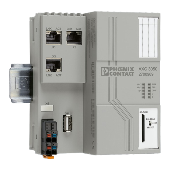
Description of the AXC 3050 controller Connection and operating elements Figure 2-6 Structure of the controller The controller for Axioline consists of the following components: Bus base module Reset buttons PROG (X4) service and programming interface Electronics module Ethernet interfaces (X1, X2, X3) FE tab (X5);... -
Page 20: Diagnostics And Status Indicators
AXC 3050 Diagnostics and status indicators The descriptions for diagnostics and status indicators apply to all controllers for Axioline F listed on the inner cover page of this user manual. The diagnostics and status indicators are used for quick local error diagnostics. -
Page 21: Diagnostics And Status Indicators Of The Controller
(no application program available in the controller). A PROFINET controller has established an active communi- cation connection to the AXC 3050 (PROFINET device) or the PROFINET device function is disabled. The BF-D LED is disabled by default. It is only illu-... - Page 22 AXC 3050 Table 2-1 Diagnostics and status indicators of the controller Color Meaning Status Description The IEC 61131 runtime system/controller is in debug mode, i.e., debug mode has been activated in PC Worx (break- Debug mode point(s) set and/or variable(s) forced).
- Page 23 Description of the AXC 3050 controller Table 2-1 Diagnostics and status indicators of the controller Color Meaning Status Description Device temperature in permitted range Overtemperature Red on Maximum permitted device temperature exceeded ETH: Ethernet interfaces Connection not established successfully Green...
-
Page 24: Mode Selector Switch
AXC 3050 Mode selector switch The mode selector switch is used to define the operating state of the controller. Function: device firmware update The mode selector switch also offers the option of triggering a firmware update. Read fur- ther details in Section “Mode selector switch triggers update via USB stick or SD card” on page 133. -
Page 25: Controller Operating Modes
Description of the AXC 3050 controller Table 2-2 Controller operating modes Operating Explanation mode MRESET Retain data and the application program are deleted. Press the mode selector switch as follows to delete the retain data and application program (please refer to Figure 2-9 on page 25): •... -
Page 26: Reset Button (Concealed)
AXC 3050 Reset button (concealed) 8686A004 Figure 2-10 Reset button (pos. 1, concealed) The reset button on the controller can only be operated with a pointed object (e.g., a pen) and is therefore protected against accidental activation. If the reset button is actuated during operation, the controller's response depends on how long you press the reset button for. - Page 27 Section “Operating the controller with or without plug-in parameterization memory (SD card/USB stick)” on page 99. Only use an SD card provided by Phoenix Contact (for ordering data, see Section “Acces- sories” on page 132).
-
Page 28: Internal Basic Circuit Diagram
RJ45 LNK ACT BOOT USB A Chipset INIT Overtemperature μP Local bus 24 V Figure 2-11 Internal basic circuit diagram (AXC 3050) Key: μP Microprocessor Transmitter Chipset Chipset PROG service/programming interface USB interface (USB A) Reset button RJ45 RJ45 interface... -
Page 29: Interfaces
This section describes the interfaces of the controller, including the possible communication paths. 2.10.1 Communication paths The communication path to the AXC 3050 controller must be determined before communi- cation with the controller can take place. The following communication paths are available on the controller: 8686A005... -
Page 30: Ethernet Interface And Pin Assignment
AXC 3050 2.10.1.1 Ethernet Three standardized Ethernet interfaces(X1/X2/X3) are available at the AXC 3050 controller for connecting the Ethernet network. The Ethernet network is connected via RJ45 sockets. Use an Ethernet cable according at least to CAT5 of IEEE 802.3. -
Page 31: Connecting Cable Between Pc And Axc 3050
PROG service/programming interface (X4: Micro USB B socket) In order to use the X4 USB interface of the AXC 3050, the “Phoenix Contact USB RNDIS Driver V1.00 xyy.exe driver must be installed (yy = 32/64, depending on whether you use a 32 or 64-bit operating system)”, see Section 4.2 on page 47. -
Page 32: Usb Interface (Usb A)
99 – Section “Copy/Update function via plug-in parameterization memory (USB stick)” on page 104 – Section “Updating the AXC 3050 firmware” on page 133 2.11 Connection for the supply voltage Figure 2-17 Terminal points for the supply voltage... -
Page 33: Bus Base Module
Description of the AXC 3050 controller 2.12 Bus base module Bus base modules carry the communications power and the bus signals from the controller through the Axioline F station (local bus). A bus base module is supplied with the controller. - Page 34 AXC 3050 PHOENIX CONTACT 8686_en_01...
-
Page 35: Mounting/Removal And Power Supply
Before working on the station, controller or module, disconnect the power to the station. NOTE: Before mounting or removing the controller, make sure that the supply voltage is switched off and cannot be switched on again by unauthorized persons. 8686_en_01 PHOENIX CONTACT... -
Page 36: Mounting Position
The AXC 3050 controller is mounted on a 35 mm standard DIN rail using the bus base mod- ule. The controller is mounted perpendicular to the DIN rail. - Page 37 Note the ambient temperatures and any other special features (e.g., derating) specified in the device/module-specific documentation for the devices/modules installed in the Axioline F station. The controller must only be mounted or removed within a temperature range from -5°C to +60°C. 8686_en_01 PHOENIX CONTACT...
-
Page 38: Structure Of An Axioline F Station
Structure of an Axioline F station The following figure shows an example structure of an Axioline F station: Figure 3-2 Structure of an Axioline F station with AXC 3050 controller Key: DIN rail End clamp (e.g., CLIPFIX 35-5; Order No. 3022276) -
Page 39: Mounting Bus Base Modules
Make sure that the device plug for the bus base connection is situated above the cor- responding socket on the bus base module. Figure 3-4 Snapping on the controller Connecting Ethernet • Connect the Ethernet network to the RJ45 sockets. Figure 3-5 Connecting Ethernet 8686_en_01 PHOENIX CONTACT... -
Page 40: Connecting A Solid Cable
AXC 3050 Connecting the supply Observe the notes in Section “Connection for the supply voltage” on page 32 when assem- voltage bling the plug for the supply voltage. • Strip 8 mm off the cable. Fit the cable with a ferrule if required. -
Page 41: Removing The Controller
• Open the spring by pressing on the spring lever with a screwdriver (A). • Remove the cable (B). 8686A010 Figure 3-9 Removing the cable 8686_en_01 PHOENIX CONTACT... -
Page 42: Removing The Supply Plug
AXC 3050 Removing the supply plug • Release the locking latch (A), tilt the plug upwards slightly (B), and remove it from the controller (C). 8686A011 Figure 3-10 Removing the supply plug Removing the Ethernet If present, release the RJ45 plug for the Ethernet connection by pressing on the snap-in lug plug and remove the plug. -
Page 43: Replacing The Controller
The controller behaves like a capacitive load when it is switched on. WARNING: Loss of electrical safety when using unsuitable power supplies The AXC 3050 is designed exclusively for protective extra-low voltage (PELV) operation according to EN 60204-1. Only PELV according to the defined standard may be used for supply purposes. -
Page 44: Figure 3-12: Overload Range With Fall-Back Characteristic Curve
Some electronically controlled power supplies have a fall-back characteristic curve (see Figure 3-12). They are not suitable for operation with capacitive loads. For information on power supply units from Phoenix Contact that can be used, please re- fer to Section “Accessories” on page 132. -
Page 45: Connecting The Power Supply/Switch-On
PC Worx via BootP (see Section “Assign- ing the IP addresses using a BootP server” on page 54). The AXC 3050 is now fully initialized and ready for operation. IP address settings can The AXC 3050 can be accessed via the previ-... -
Page 46: Inserting/Removing The Parameterization Memory
AXC 3050 Inserting/removing the parameterization memory >Click< >Click< Figure 3-14 Inserting (A) and removing (B) the parameterization memory NOTE: Avoiding damage Should it, in certain cases, be necessary to use a pointed object to insert/remove the SD card, avoid letting the SD card slip in order to prevent any damage to the device/SD card. -
Page 47: The Axc 3050 Controller Under Pc Worx
The AXC 3050 controller under PC Worx Installing USB driver – USB device recognition The AXC 3050 is detected by the Windows operating system as a USB device, if your PC supports this function and you have installed an appropriate USB driver. -
Page 48: Assigning Ip Addresses For The Controller
In the Windows Control Panel, check the settings for your PC network adapter. • If necessary, adjust these settings so that the AXC 3050 can be accessed in your net- work via the IP address used in the example project. -
Page 49: Mac Addresses Of The Axc 3050
The AXC 3050 controller under PC Worx 4.4.1 MAC addresses of the AXC 3050 The AXC 3050 has two MAC addresses. Each of these MAC addresses is assigned to one of the three Ethernet interfaces (X1, X2, and X3). Assignment is according to the following scheme:... -
Page 50: Assigning Ip Addresses Via The Prog Usb Interface
Connect the PC, on which the PC Worx software is running, to the PROG (X4) USB inter- face of the AXC 3050 via a free USB interface. If your PC supports automatic detection of USB devices, the PC will immediately detect the AXC 3050 if you previously selected to in- stall the USB driver (see Section 4.1 on page 47). -
Page 51: Figure 4-2: Device Details - Extended Settings
The AXC 3050 controller under PC Worx Figure 4-2 Device Details – Extended Settings Perform the following steps for the settings in the example for each Ethernet interface (LAN1 (X1), LAN2 (X2) and LAN3 (X3)), in order to assign an IP address to each interface. -
Page 52: Figure 4-3: "Settings Communication Path - Usb: Axc 3050" Dialog Box
Figure 4-4 Transmission of network settings successful Transferring settings to In order for the transferred network settings to take effect in the controller, the AXC 3050 the controller must be restarted. • In the “Activate Network Settings” area, click on the “Restart Controller” button (D in Figure 4-2 on page 51). -
Page 53: Figure 4-5 Activate Network Settings: Service Executed Successfully
Successful execution of the service will be displayed in the status window. Figure 4-5 Activate Network Settings: Service executed successfully The network settings assigned to the AXC 3050 are active. Testing network settings You can test whether the settings are working correctly on the “Communication” tab in the “Device Details”... -
Page 54: Assigning The Ip Addresses Using A Bootp Server
A corresponding IP address and subnet mask have been assigned in PC Worx for the MAC address. Once the IP data has been transferred to the AXC 3050 successfully, PC Worx sends a cor- responding acknowledgment message. Assigning IP settings... -
Page 55: Figure 4-7 Ip Address Settings - Entering Mac Address(Es)
The AXC 3050 controller under PC Worx 8686A021 Figure 4-7 IP address settings – entering MAC address(es) Establishing a connection • Establish an Ethernet connection between your PC and the Ethernet interface of the controller, to which you wish to assign the IP address settings (Ethernet interface X3 in the example). -
Page 56: Figure 4-8: "Extras, Bootp/Snmp/Tftp-Configuration
AXC 3050 Calling/activating BootP • In the PC Worx menu bar, select the “Extras, BootP/SNMP/TFTP-Configuration...” menu. Figure 4-8 “Extras, BootP/SNMP/TFTP-Configuration...” menu • Activate the BootP server by clicking “Activate BootP” (A). Figure 4-9 “Activate BootP” (A) and “Deactivate BootP” (B) buttons Applying the IP set- •... -
Page 57: Read Axioline
The AXC 3050 controller under PC Worx Deactivate BootP • Deactivate the BootP server by clicking “Deactivate BootP” (B in Figure 4-9 on page 56). The shutdown is indicated in the message window (refer to Figure 4-10). PC Worx quick start guide – further information For additional information on setting the IP address with PC Worx, please refer to the quick start guide for the software. -
Page 58: Figure 4-12 Read Axioline - Axioline Modules That Have Not Yet Been Read In
AXC 3050 All Axioline modules connected to the controller are displayed in the “Read Axioline” dialog box that opens. Modules marked in black have not yet been read into the PC Worx project; modules marked in green have been configured. When the “Re-insert all modules” option is selected, modules that have already been configured are also read in again. -
Page 59: Figure 4-16 Read In Axioline Devices
The AXC 3050 controller under PC Worx The read in Axioline devices are read in with their default configuration and are displayed in the “Bus Structure” window. The device details for a device can be displayed by selecting it. Figure 4-16... -
Page 60: Axc 3050 As Profinet Controller
The sections 4.3 “Start – Creating a new project” and 4.4 “Assigning IP addresses for the controller” describe how you create a project in PC Worx with AXC 3050 as a PROFINET controller and how you assign IP address settings to the controller. -
Page 61: Figure 4-18 "Read Profinet" Dialog Box
The AXC 3050 controller under PC Worx The “Read PROFINET” dialog box that opens shows the PROFINET devices that have been detected in the connected network. Figure 4-18 “Read PROFINET” dialog box • Select the Axioline PROFINET AXL F BK PN BK module and insert it as a PROFINET device by clicking on the “Insert”... -
Page 62: Figure 4-20 Profinet Devices Inserted
AXC 3050 • Confirm your selection with “OK”. If a PROFINET device name has not yet been assigned for the PROFINET device to be in- serted, you are prompted to assign one by PC Worx at this point. If PROFINET Station- names have already been assigned, follow the steps below. -
Page 63: Figure 4-21 Profinet Devices: Device Parameters (Profinet, Axioline)
The AXC 3050 controller under PC Worx Device parameters The device parameters of the PROFINET device are displayed in the device details in the “Device parameters“ tab. Figure 4-21 PROFINET devices: device parameters (PROFINET, Axioline) Stationname/IP address In the “PROFINET Stationnames” tab, you can assign a PROFINET name and its IP address settings to the PROFINET device marked in the bus structure (B and C in Figure 4-22). -
Page 64: Figure 4-23 Profinet Device: Ip Address Settings Assigned
AXC 3050 In the example, the PROFINET BK module AXL F BK PN (A in Figure 4-22) has already been assigned the PROFINET name “axl-f-bk-pn-1”, but not yet the IP address. • Click on the “Assign IP” button (D in Figure 4-22), to assign the IP address displayed in the “Bus structure”... -
Page 65: Axc 3050 As A Profinet Device
The AXC 3050 controller under PC Worx AXC 3050 as a PROFINET device This section uses an example to describe how to integrate the AXC 3050 as a PROFINET device in a PC Worx project. The function as a PROFINET device for AXC 3050 is optionally available for the PROFINET controller function. -
Page 66: Figure 4-26 Device Interface Selection Executed Successfully
Successful execution of the service will be displayed in the status window (see Figure 4-26 on page 66). To activate the above settings on the AXC 3050, the controller must be restarted. • In the “Activate Network Settings” area, click on the “Restart Controller” button (refer to D in Figure 4-2 on page 51). - Page 67 The BF LED flashes following successful execution of the service. This indicates that a link status is available and there is no communication connection to the PROFINET IO control- ler. Now you can read the AXC 3050 as a PROFINET device in a PC Worx project. Integrating the AXC 3050...
-
Page 68: Figure 4-28: Bus Structure: Profinet Context Menu "Read Profinet
Figure 4-29 “Read PROFINET” dialog box • Select the AXC 3050 and insert it as a PROFINET device by clicking on the “Insert” but- ton. • If the following “Select PROFINET device description” dialog box opens, select the de- vice description that corresponds to the AXC 3050. -
Page 69: Figure 4-30 Axc 3050 Inserted As A Profinet Device
The process data of the PROFINET device will be displayed on the “Process Data” tab in the “Device Details” window. Figure 4-31 AXC 3050 as a PROFINET device: Process Data The AXC 3050 is now available as a PROFINET device in the PC Worx project. 8686_en_01 PHOENIX CONTACT... -
Page 70: Diagnostics Of The Axioline I/O System
To display the diagnostics as shown in the following section, compile the PC Worx project PC Worx project to the and send it to the AXC 3050. Then switch the mode selector switch to the RUN/PROG po- controller sition. The AXC 3050 is in the RUN state, once all steps required have been performed. -
Page 71: Figure 4-33 Diag+ - Communication Path For Axc 3050
Figure 4-33 Diag+ – communication path for AXC 3050 Make sure that the AXC 3050 controller is set as the communication path and “Axioline Modules” is set as the device type in the “Device Representation” area. In this example, the “Slot Number”... -
Page 72: Figure 4-35 Diagnostic View: Selecting Axioline Diagnostic
AXC 3050 • At the top of the “Diag+” dialog box, select “Axioline Diagnostic” as the view. Figure 4-35 Diagnostic view: selecting Axioline Diagnostic Diag+ then switches to diagnostic view of the connected Axioline system configured in PC Worx. Figure 4-36... -
Page 73: Figure 4-37 Axioline Module Axl F Di 16/1 Hs 1H: No Error
The AXC 3050 controller under PC Worx The following dialog box shows an Axioline module that is operating without errors: Figure 4-37 Axioline module AXL F DI 16/1 HS 1H: No error 8686_en_01 PHOENIX CONTACT... -
Page 74: Figure 4-38 Axioline Module Axl F Di 16/1 Hs 1H: Sensor Supply Not Present
AXC 3050 Any errors that occur are diagnosed by Diag+ and displayed. In the following example, the supply voltage for the AXL F DI 16/1 HS 1H Axioline module is not present. Diag+ shows the following: Figure 4-38 Axioline module AXL F DI 16/1 HS 1H: Sensor supply not present... -
Page 75: Figure 4-39 Axc 3050 Controller - Peripheral Error
The AXC 3050 controller under PC Worx When the controller is selected, the error is displayed as follows: Figure 4-39 AXC 3050 controller – Peripheral error Diagnostics can be used to identify errors in your application. 8686_en_01 PHOENIX CONTACT... -
Page 76: Figure 4-40 Controller Context Menu
AXC 3050 Controller context menu in The controller context menu in Figure 4-40 offers options for influencing the state of the Diag+ Axioline F local bus. Figure 4-40 Controller context menu The following menu items can be selected: Refresh Refreshes the view in the “Diag+” dialog box. -
Page 77: Setting The Realtime Clock Under Pc Worx
PC Worx version used. 4.10 Download changes The “Download Changes” function supports the AXC 3050 as of the specified device ver- sion in conjunction with the specified versions of the PC Worx software. Table 4-4 Version information for “Download Changes”... -
Page 78: Parameterization Memory And Internet Explorer
You can limit access to the parameterization memory by using the firmware service, which is sent from PC Worx to the AXC 3050. Read further details in Section “User administra- tion – limiting access to the parameterization memory” on page 95. -
Page 79: Figure 4-42 Internet Explorer: File And Folder Structure Of The Parameterization Memory
The AXC 3050 controller under PC Worx If you have not deactivated access to the parameterization memory, the Internet Explorer window that opens displays the file and folder structure on the parameterization memory. Do not edit any files as Internet Explorer does not store modified data. For the current state to be displayed, refresh the display after every action by means of the “View, Refresh”... -
Page 80: Internet Explorer Ftp Functionality
AXC 3050 4.11.1 Internet Explorer FTP functionality • Activate this setting in Internet Explorer under “Tools, Internet Options, Advanced”. Figure 4-44 Internet Options: Enable folder view for FTP sites PHOENIX CONTACT 8686_en_01... -
Page 81: Activating/Deactivating The Ftp Server
The AXC 3050 controller under PC Worx 4.11.2 Activating/deactivating the FTP server To protect the controller against unauthorized access, it may be necessary to deactivate the FTP server. The CPU_Set_Value_Request service with Var ID 0172 is used for this. This service activates or deactivates the FTP server for the runtime of the firmware. -
Page 82: Event Task For The Voltage Failure Event
If the supply voltage fails in the application, it may make sense to start data backup auto- matically, e.g., to protect the application. In this case, an event task can be defined in PC Worx for the AXC 3050, which is started in the case of the “voltage failure” event. To do this, proceed as follows: •... -
Page 83: Figure 4-48 "Task Settings For Powerof" Dialog Box
The AXC 3050 controller under PC Worx In the “Task settings for PowerOf” dialog box, the voltage failure is displayed in the “Event” field. You can set the priority of the event task and the watchdog time in this dialog box. -
Page 84: Function Blocks For Handling Files On The Parameterization Memory
AXC 3050 4.13 Function blocks for handling files on the parame- terization memory The function blocks are used to access files from within the application program. Some of the blocks support multiple instantiation. This means that it is possible to work with a number of different files within the same project. -
Page 85: Function Blocks For Ethernet Communication
The AXC 3050 controller under PC Worx 4.14 Function blocks for Ethernet communication The function blocks are used to establish Ethernet communication between two communi- cation partners. The IP communication blocks listed below enable IEC 61131-5-compliant communication between controllers via Ethernet or communication between controllers and Ethernet de- vices via TCP/IP or UDP. -
Page 86: Function Blocks For The "Fast Counters" Function
AXC 3050. The AXC 3050 supports the “fast counters” function. This means that the controller can han- dle any number of inputs in the Axioline F local bus as fast inputs and can start counters and/or event tasks with these inputs. - Page 87 The AXC 3050 controller under PC Worx Table 4-7 Inputs of the CNT1 and CNT2 function blocks Name Data type Description ENABLE BOOL Enabling of parameterization With a rising edge at ENABLE, the values parameterized at the MODE and EDGE inputs are applied.
-
Page 88: Figure 4-51 Selecting The "Event Value Cntx" Event
AXC 3050 Table 4-7 Inputs of the CNT1 and CNT2 function blocks Name Data type Description EVENT_VALUE UDINT Triggering of the event task If the counter status reaches the value specified here, an event task can be triggered. In order to use this function, an event task must be defined and the corresponding “Event Value CNTx”... - Page 89 The AXC 3050 controller under PC Worx The function blocks are only processed as long as the AXC 3050 controller is in the RUN state. When the controller goes from the RUN state to the STOP state, the current counter status is saved.
-
Page 90: Counter Operating Modes
AXC 3050 4.15.1 Counter operating modes Specify the counter mode at the MODE input of the function block. Use the operating mode to define the presets for the counting direction, reset of the counter status, and start of the counting process. - Page 91 The AXC 3050 controller under PC Worx Table 4-10 Counter operating modes MODE CNT1_F1 or CNT1_F2 or CNT1_Reset CNT1_Enable Counter operating mode [hex] CNT2_F1 CNT2_F2 CNT2_Reset CNT2_Enable Assigned to any input from the connected Axioline F local bus Counter with external clock and counting di-...
- Page 92 AXC 3050 Key: Clock The counter counts the signal edges on the assigned input, which were determined on the EDGE input of the function block. Clock, counting up The counter counts up the signal edges on the assigned input, which were determined on the EDGE input of the function block.
-
Page 93: Function Blocks For Axioline/Acyclic Pdi Communication
The AXC 3050 controller under PC Worx 4.16 Function blocks for Axioline/acyclic PDI communi- cation In order to provide a flexible and universal option for the applicative parameterization of Axioline F modules, function blocks are available for PDI communication. These blocks en- able both startup parameterization and online parameterization, i.e., parameterization dur-... - Page 94 AXC 3050 PHOENIX CONTACT 8686_en_01...
-
Page 95: Useful Information On Axc 3050
User administration – limiting access to the param- eterization memory Firmware service for acti- PC Worx offers the option to limit access to the parameterization memory of the AXC 3050 vation/deactivation and therefore protect against unauthorized access. For this purpose, you can define a user name and password using the firmware service CPU_Set_Value_Request. -
Page 96: Figure 5-2: Deactivating Access Protection To The Parameterization Memory
Figure 5-2 Deactivating access protection to the parameterization memory If access protection to the parameterization memory of the AXC 3050 is activated, proceed as described below, if you wish to display the content of the parameterization memory. If you want to access the parameterization memory using a web browser, we recommend switching off the buffer (cache) of the web browser, as otherwise potential content of the parameterization memory may be displayed despite the activated access protection. -
Page 97: Figure 5-4 User Name And Password
Useful information on AXC 3050 • In the following dialog box, enter the user name and password and confirm your entry. Figure 5-4 User name and password The content of the parameterization memory is then displayed in Internet Explorer. Figure 5-5... -
Page 98: Figure 5-6: Access To The Parameterization Memory Not Possible
AXC 3050 Password access to Win- The user administration installed indicates that access to the parameterization memory is dows Explorer not possible. Figure 5-6 Access to the parameterization memory not possible Enter the FTP address according to Figure 5-7 including the user name and password and confirm your entry by pressing Return. -
Page 99: Operating The Controller With Or Without Plug-In Parameterization Memory (Sd Card/Usb Stick)
Useful information on AXC 3050 You can now make changes to the files or delete them, for example. Operating the controller with or without plug-in pa- rameterization memory (SD card/USB stick) If required, you can operate the controller with just the device-internal parameterization memory or with a plug-in parameterization memory (SD card/USB stick). -
Page 100: Using The Plug-In Parameterization Memory
AXC 3050 • Switch on the supply voltage of the controller. NOTE: All data from the internal parameterization memory is deleted Once the controller has been operated with the SD card, there is no data available on the internal parameterization memory. The controller therefore does not have an IP address. - Page 101 (SD card) the X3 IP address settings to the Ethernet interface, in order to communicate with the AXC 3050 in a PROFINET net- work. A PC Worx can then be downloaded to the controller via the X3 interface or via a USB connection.
- Page 102 As a minimum, you need to assign the X3 IP address set- tings to the Ethernet interface, in order to communicate with the AXC 3050 in a PROFINET network. A PC Worx can then be downloaded to the controller via the X3 interface or via a USB connection.
- Page 103 Disk”). You can access this memory via PC Worx function blocks (FILE_...). In the event of voltage failure, the AXC 3050 saves the most important control data (retain data) on the main memory, in this case the inserted SD card.
-
Page 104: Copy/Update Function Via Plug-In Parameterization Memory (Usb Stick)
Copy/Update function via plug-in parameterization memory (USB stick) The Copy/Update function enables the AXC 3050 controller firmware to be updated by means of USB stick. In addition, application-specific data can be saved in the “CFROOT” directory, copied to a USB stick or transferred from here to the active parameterization memory (internally or inserted SD card). -
Page 105: Pc Worx: Activating The Function Via Dialog Box
PC Worx – Copy/Update function The Copy/Update function is triggered by pressing the mode selector switch. For the exact procedure on actuating the mode selector switch, please refer to Section “Updating the AXC 3050 firmware” on page 133 Key: A Read Read the current status set in the controller. -
Page 106: Pc Worx: Activating The Function Via Firmware Service
AXC 3050 C Successful execution of the service will be displayed in the status window. D Options for using the external parameterization memory – Copy/Update function deactivated. – Update function activated (USB ⇒ PLC). – Copy/Update function activated (USB ⇔ PLC). -
Page 107: Setting "Use The External Sd Card As Additional Memory
Useful information on AXC 3050 5.4.1 Setting “Use the external SD card as additional memory...” In this setting, a corresponding directory is created in the “CFROOT” directory (basic con- troller directory) for the inserted parameterization memory. You can display these directo- ries, for example, if you access the controller via FTP (refer to Section “Parameterization... -
Page 108: Setting "Use The External Sd Card As Main Memory
Setting “Use the external SD card as main memory ...” The inserted SD card functions in this setting as a parameterization memory of AXC 3050. If you have inserted a USB stick, its directory will be presented as shown in Figure 5-11. - Page 109 Useful information on AXC 3050 Figure 5-13 FILE function blocks in PC Worx 8686_en_01 PHOENIX CONTACT...
- Page 110 AXC 3050 PHOENIX CONTACT 8686_en_01...
-
Page 111: System Variables And Status Information
AXC 3050 controller. The following descriptions of system variables and status information apply to PC Worx. The AXC 3050 controller has a register set, which is used for diagnostics and easy control of the controller and Axioline F local bus. -
Page 112: Diagnostic Parameter Register
AXC 3050 Diagnostic parameter register The diagnostic parameter register provides additional information about the error indicated in the diagnostic status register. The error code is stored in the diagnostic parameter regis- ter and the error location in the extended diagnostic parameter register. The error location is stored as a slot number. -
Page 113: Profinet System Variables
(low-priority maintenance alarm) for the active connection. The device can be identified using the RALRM diagnostic block. PNIO_FORCE_FAILSAFE BOOL All PROFINET devices are prompted to set/assume their configured substitute values. PNIO_CONFIG_STATUS BOOL Current configuration status of the context manager 8686_en_01 PHOENIX CONTACT... - Page 114 The PROFINET controller configuration has not been applied due to a serious error and the PROFINET controller is not started. Please contact Phoenix Contact. If one of these values is set, it is now possible to decide from the program whether the sys- tem should continue operating.
-
Page 115: Profinet System Variables (Profinet Device Function)
Applicative system redundancy – number of the PROFI- NET device currently connected to the PROFINET con- troller Specifies from which higher-level PROFINET controller the data in the PROFINET device originates (see Figure 2-5 on page 17). No PROFINET controller PROFINET controller A PROFINETcontroller B 8686_en_01 PHOENIX CONTACT... -
Page 116: Iec 61131 Runtime System
System variables of the IEC 61131 runtime system System variable Type Meaning PLCMODE_ON BOOL PLC status ON: The runtime system on the AXC 3050 controller is ready to operate. PLCMODE_LOADING BOOL PLC status LOADING: The application program is loading. PLCMODE_RUN BOOL PLC status RUN: the application program is running. -
Page 117: Control Processor
System variables of the parameterization memory System variable Type Meaning FLASHCARD_PRESENT BOOL Phoenix Contact SD card inserted in the device. The SD card is intended for use with AXC 3050. FLASHCARD_REPLACED BOOL Phoenix Contact SD card replaced in the device. FLASHCARD_REMOVED BOOL Phoenix Contact SD card removed from the device. -
Page 118: Usb Memory Stick
System variable Type Meaning USBDISK_PRESENT BOOL Phoenix Contact USB stick inserted in the X6 USB interface. The USB stick is intended for use with AXC 3050. USBDISK_REPLACED BOOL Phoenix Contact USB stick replaced in the X6 USB interface. USBDISK_REMOVED BOOL Phoenix Contact USB stick removed from the X6 USB interface. -
Page 119: Temperature Monitoring
The Ethernet interface is connected to the network. LAN_PORT3_100MBIT BOOL The transmission rate of the Ethernet interface is 100 Mbps. LAN_PORT3_FULL_DUPLEX BOOL The Ethernet interface is set to full duplex mode. LAN_PORT3_LINK BOOL The Ethernet interface is connected to the network. 8686_en_01 PHOENIX CONTACT... -
Page 120: Fast Counters
AXC 3050 6.15 Fast counters The following table lists the system variables for the “fast counters” function supported by AXC 3050. NOTE: Only use these system variables for testing purposes in Debug mode! These system variables reflect the state of the inputs assigned to the Axioline I/O modules in PC Worx in the “Fast I/O coupling”... -
Page 121: Web-Based Management Wbm
As the web server operates using the Hyper Text Transfer Protocol, a standard browser can be used. Access is via the URL “http://IP address of the device”. Example: “http://192.168.0.2”. You can call up the WBM via every Ethernet interface of the AXC 3050. We recommend the use of Microsoft Internet Explorer 9.0. -
Page 122: Functions/Information In Wbm
AXC 3050 Functions/information in WBM The WBM is split into the following areas: – Information: general device information – Diagnostics: device-specific diagnostics 7.3.1 Web page information Web page general data Here you will find general details for the device, e.g., device version and order number as well as manufacturer details. -
Page 123: Web Page Technical Data
Web-based management WBM Web page technical data Here you will find technical details on the device, e.g., on the ambient conditions, device memory, and supply voltage. Figure 7-3 Web page technical data 8686_en_01 PHOENIX CONTACT... -
Page 124: Web Page Diagnostics Indicators
AXC 3050 Web page diagnostics indicators This page describes the meaning of the diagnostics indicators (LEDs). Figure 7-4 Web page diagnostics indicators PHOENIX CONTACT 8686_en_01... -
Page 125: Web
Web-based management WBM 7.3.2 Web page diagnostics Web page controller Here you will find a brief description of the LED indicators, which are displayed during the runtime of the device. Figure 7-5 Web page controller 8686_en_01 PHOENIX CONTACT... -
Page 126: Web-Visu Web Page (Web Visualization)
AXC 3050 Web page network The IP address settings assigned to the device are displayed here. Figure 7-6 Web page network 7.3.3 Web-Visu web page (web visualization) Calling the Web-based management in an existing web visualization From a web visualization running on the controller, call up the WBM by entering the “IP address/webui”... -
Page 127: Technical Data And Ordering Data
Depth 74 mm Note regarding measurements The specified depth applies when using a TH 35-7.5 DIN rail (according to EN 60715), (e.g., NS 35/7,5... from Phoenix Contact, see “Ordering data” on page 131). General data Color Traffic gray A RAL 7042 Weight Approx. -
Page 128: Power Supply
AXC 3050 Axioline F local bus interface Transmission speed 100 Mbps Number of local bus devices that can be connected 63, maximum NOTE: Electronics may be damaged when overloaded – observe the current consumption of the Axioline F modules. Observe the current consumption of each device when configuring an Axioline F station. It is specified in every module-specific data sheet. -
Page 129: Ethernet Interface
PDEV function not supported Error messages to the higher-level control or computer system None (PROFINET device) Diagnostics and status indicators IEC 61131 runtime system (PLC) RUN, FAIL, DBG, BOOT Ethernet (ETH) LNK, ACT Axioline diagnostics D, E 8686_en_01 PHOENIX CONTACT... -
Page 130: Realtime Clock
Typ. 10 days (the buffer time of the clock depends on the ambient tempera- ture of the controller). If the AXC 3050 is not supplied with voltage for longer than this time, we rec- ommend setting the time via SNTP. -
Page 131: Ordering Data
Type Order No. Axiocontrol for the direct control of Axioline F I/Os. With three Ethernet inter- AXC 3050 2700989 faces for the additional connection of distributed I/Os via PROFINET, Modbus TCP or TCP/IP. Programming according to IEC 61131-3. Including connector plug and marking field. -
Page 132: Accessories
See current catalog from Phoenix Contact (phoenixcontact.net/products) 8.2.4 Documentation Description Type Order No. “Modbus TCP with Phoenix Contact controllers” application note AH EN MODBUS TCP – “Axioline F: system and installation” user manual UM EN AXL F SYS INST –... -
Page 133: A Appendix: Service, Maintenance, Derating, And Ambient Conditions
Updating the AXC 3050 firmware Such firmware updates (software integrated on the AXC 3050) are exclusively used for add- ing new functions that are implemented within the scope of continuous product improve- ment. No firmware update is required for normal system operation. - Page 134 135): NOTE: Firmware update: voltage not switching off – device defect possible Avoid switching of the AXC 3050 supply voltage during the firmware update. Switching off can result in damage to the device! Switch to and hold the MRESET position button.
-
Page 135: Firmware Update: Timing And Led Indicators
Updating the AXC 3050 firmware 2 Hz (A; ... 3 sec) 1 Hz 2 Hz (B; ... 3 sec) FAIL FAIL FAIL 1 Hz 2 Hz BOOT BOOT Firmware Update MRESET STOP MRESET STOP MRESET STOP 1 ... 2 sec 0 ... 2 sec 1 ... - Page 136 AXC 3050 PHOENIX CONTACT 8686_en_01...
-
Page 137: B Appendix
Structure of the bus base module ............33 Section 3 Figure 3-1: Mounting position ................36 Figure 3-2: Structure of an Axioline F station with AXC 3050 controller ....38 Figure 3-3: Mounting bus base modules ............... 39 Figure 3-4: Snapping on the controller ..............39 Figure 3-5: Connecting Ethernet ................ - Page 138 New project created: UM_AXC_3050 – project information ....48 Figure 4-2: Device Details – Extended Settings ............ 51 Figure 4-3: “Settings Communication Path – USB: AXC 3050” dialog box .... 52 Figure 4-4: Transmission of network settings successful ........52 Figure 4-5: Activate Network Settings: Service executed successfully ....
- Page 139 List of figures Figure 4-32: Calling Diag+ ..................70 Figure 4-33: Diag+ – communication path for AXC 3050 ........71 Figure 4-34: Selecting diagnostic view ..............71 Figure 4-35: Diagnostic view: selecting Axioline Diagnostic ........72 Figure 4-36: Diag+: Axioline Diagnostic ..............72 Figure 4-37: Axioline module AXL F DI 16/1 HS 1H: No error .........
- Page 140 AXC 3050 Figure 5-12: Parameterization memory: directory structure in “CFROOT” basic directory ....... 108 Figure 5-13: FILE function blocks in PC Worx ............109 Section 7 Figure 7-1: WBM user interface: selecting the language ........121 Figure 7-2: Web page general data ..............122 Figure 7-3: Web page technical data ..............
-
Page 141: B 2 List Of Tables
System variables of the USB memory stick ........118 Table 6-10: System variables of the power storage and realtime clock ....118 Table 6-11: System variables of the power supplies..........118 Table 6-12: System variables of the mode selector switch ........118 8686_en_01 PHOENIX CONTACT... - Page 142 AXC 3050 Table 6-13: System variables of internal device temperature monitoring....119 Table 6-14: System variables of the system time..........119 Table 6-15: System variables of the Ethernet interfaces........119 Table 6-16: System variables for the “fast counters” function ....... 120...
-
Page 143: B 3 Index
Compiling PC Worx project and sending it to the controller ........70 Loading project Sizing of the power supply .......... 43 Compiling PC Worx project and Status indicators ............20 sending it to the controller ........70 8686_en_01 PHOENIX CONTACT... - Page 144 AXC 3050 Updating the firmware ..........133 PHOENIX CONTACT 8686_en_01...
- Page 145 Index 8686_en_01 PHOENIX CONTACT...
- Page 146 AXC 3050 PHOENIX CONTACT 8686_en_01...
Need help?
Do you have a question about the AXC 3050 and is the answer not in the manual?
Questions and answers