
Related Manuals for Phoenix Contact AXC F XT SPLC 1000


Summary of Contents for Phoenix Contact AXC F XT SPLC 1000
- Page 1 Installation and operation of the left-alignable AXC F XT SPLC 1000 safety-related controller User manual UM EN AXC F XT SPLC 1000...
- Page 2 Prior to commissioning the device, observe the following: • Ensure that you operate the device with the latest firmware version. If a firmware update is necessary, please contact your nearest Phoenix Contact representative. The firm- ware may only be updated by trained personnel. •...
-
Page 3: Table Of Contents
Transport ......................23 Storage........................ 23 Unpacking ......................23 Description of the AXC F XT SPLC 1000 ..................25 General description of the SPLC 1000 ..............25 Description of the safety-related functioning of the SPLC 1000 ......27 Calculating/determining the response time (Safety Function Response Time, SFRT) ...................... - Page 4 AXC F XT SPLC 1000 Possible fields of application of the SPLC 1000........... 45 SPLC 1000 components..................45 3.5.1 Connection and operating elements ............ 45 3.5.2 SPLC 1000 printing and test mark ............46 Diagnostic and status indicators ................47 Internal basic circuit diagram ................
- Page 5 Transferring a safety-related project to the SPLC 1000 (specifying a controller password if necessary) ........112 6.10.3 Displaying safety-related online values ..........115 6.11 PLCnext Engineer – Debug mode ..............117 6.12 Operator acknowledge ..................118 5 / 200 PHOENIX CONTACT 109449_en_01...
- Page 6 AXC F XT SPLC 1000 Errors: Diagnostics, messages, and removal................121 Diagnostics for F-Devices.................. 121 Diagnostics for SPLC 1000................121 Possible errors....................122 7.3.1 Errors and error codes of the SPLC 1000 as the F-Host ....124 7.3.2 Errors and error codes of the SPLC 1000 as an F-Device ....130 Evaluation and acknowledgment of module-specific diagnostic messages..
- Page 7 Commissioning and parameterization ..........184 B 2.4 “Initial commissioning” and “recommissioning/device replacement” validation ................... 185 Appendix for document lists....................187 List of figures ....................187 List of tables ..................... 193 Index......................... 195 Appendix: Revision history .....................197 7 / 200 PHOENIX CONTACT 109449_en_01...
- Page 8 AXC F XT SPLC 1000 8 / 200 PHOENIX CONTACT 109449_en_01...
-
Page 9: For Your Safety
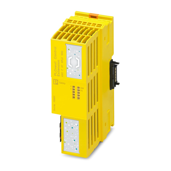
1.3.1 Purpose of this user manual The information in this document describes how the AXC F XT SPLC 1000 works, its con- trol elements, and its connection elements. The AXC F XT SPLC 1000 is a safety-related controller that, as the “PLCnext Control Extension” extension module, can be aligned to the left of an AXC F 2152 or AXC F 3152. -
Page 10: Validity Of The User Manual
AXC F XT SPLC 1000 It also describes how the AXC F XT SPLC 1000 is integrated into the software tools listed in Section “System requirements (hardware and software)” on page This information will enable you to use the device in accordance with your requirements. -
Page 11: General Safety Notes
After power up of the supply voltage or a software reset, the SPLC 1000 starts immediately – An SD card with a valid project is inserted in the PLCnext Control or – A valid project exists on the internal flash memory of the PLCnext Control and 11 / 200 PHOENIX CONTACT 109449_en_01... - Page 12 AXC F XT SPLC 1000 – The PLCnext Control mode selector switch is set to RUN. Information on the PLCnext Control mode selector switch is available in the UM EN AXL F X152 user manual. By selecting one of the options “Write and Start Project...” or “Write and Start Project Changes...”, the safety function becomes active immediately after downloading the...
-
Page 13: Field Of Application Of The Product
Field of application of the product 1.6.1 Intended use This information will enable you to use the AXC F XT SPLC 1000 (SPLC 1000 for short) in accordance with your requirements in a PROFIsafe system. – The device is a safety-related controller which supports the PROFIsafe protocol. -
Page 14: Foreseeable Misuse
PLCnext Info Center. • It is imperative that you install the AXC F XT SPLC 1000 in a lockable housing or a lockable control cabinet. The device housing is not protected against tampering, and access to the device cannot be proven. -
Page 15: Safety Notes
NOTE: Device defect due to polarity reversal Polarity reversal puts a strain on the electronics and can damage the device. • To protect the device, avoid reversing the poles of the 24 V supply. 15 / 200 PHOENIX CONTACT 109449_en_01... -
Page 16: Electrical Safety
AXC F XT SPLC 1000 Electrical safety WARNING: Hazardous shock currents and the loss of functional safety Disregarding instructions for electrical safety may result in hazardous shock currents and the loss of functional safety. In order to ensure electrical safety, please observe the following points. -
Page 17: Safety Of The Machine Or System
Safety of the machine or system The manufacturers and operators of machines and systems, in which the AXC F XT SPLC 1000 device is used, are responsible for adhering to all applicable stan- dards, directives, and legislation. Draw up and implement a... -
Page 18: Standards And Directives
The standards to which the device conforms are listed in the certificate issued by the ap- proval body and in the EC declaration of conformity (see phoenixcontact.net/products). Directives considered in the development of the AXC F XT SPLC 1000 device: –... - Page 19 UM EN AXL F X152 User manual Installing, commissioning, and operat- ing the AXC F 1152, AXC F 2152, and AXC F 3152 controllers – UM EN AXL SE SYS INST User manual Axioline Smart Elements 19 / 200 PHOENIX CONTACT 109449_en_01...
-
Page 20: System Requirements (Hardware And Software)
For trouble-free operation, follow the instructions in the software documentation. Please note: The PLCnext Engineer engineering software platform for Phoenix Contact automation controllers is compliant with IEC 61131-3. Its functionality can be extended with add-ins. PLCnext Engineer can be used as an editor for programming safety-related user applications. -
Page 21: Abbreviations Used
Abbreviation Meaning SPLC 1000 Left-alignable safety-related controller of performance class 1000 In this document, the AXC F XT SPLC 1000 is also referred to as a safety-related controller. PLCnext Control Controller with PLCnext Technology with which, thanks to the open control platform, automation projects can be realized without the re- strictions of proprietary systems. -
Page 22: Safety Hotline
AXC F XT SPLC 1000 1.14 Safety hotline If you have any technical questions, please contact the Safety Hotline: – Phone: +49 5281 946 2777 – E-mail: safety-service@phoenixcontact.com 22 / 200 PHOENIX CONTACT 109449_en_01... -
Page 23: Transport, Storage, And Unpacking
NOTE: Property damage due to noncompliance with ESD notes If the ESD notes are not observed during unpacking and packaging, the device may be- come damaged. • Observe the ESD notes during unpacking and packaging. 23 / 200 PHOENIX CONTACT 109449_en_01... - Page 24 Damaged packaging is an indicator of potential damage to the device that may have occurred during transport. This could result in a malfunction. • Submit claims for any transport damage immediately, and inform Phoenix Contact or your supplier as well as the shipping company without delay. •...
-
Page 25: Description Of The Axc F Xt Splc 1000
Description of the AXC F XT SPLC 1000 Description of the AXC F XT SPLC 1000 General description of the SPLC 1000 The SPLC 1000 is a safety-relevant controller. It is a “PLCnext Control Extension” extension module which can be aligned to the left on an AXC F 2152 or AXC F 3152. - Page 26 AXC F XT SPLC 1000 Operation with an SD card Please note in this case that, when replacing the PLCnext Control device used with an iden- tical device with suitable firmware, you can reuse the previously used SD card in the re- placement device.
-
Page 27: Description Of The Safety-Related Functioning Of The Splc 1000
Description of the AXC F XT SPLC 1000 Description of the safety-related functioning of the SPLC 1000 Behavior of the SPLC 1000 The SPLC 1000 is a powerful two-channel safety-related controller for PROFIsafe. The as the F-Host in PROFIsafe PROFIsafe security protocol is transmitted via the PLCnext Control device used and via the PROFINET network. - Page 28 AXC F XT SPLC 1000 Figure 3-1 PROFIsafe: Management/diagnostic variables for communication diagnos- tics of the SPLC 1000 F-Host To support the user, seven non-safety-related management/diagnostic variables are cre- ated by default in PLCnext Engineer for each F-Device in the data list of the safety-related controller.
- Page 29 Description of the AXC F XT SPLC 1000 PROFIsafe: F-Device com- The SPLC 1000 supports the user in monitoring and checking the communication relation- ships of the device-internal F-Device. For this purpose, analogous to the above described munication diagnostics management / diagnostic variables of the F-Host, management / diagnostic variables can also be created in the PLCnext Engineer for the F-Device of the SPLC 1000.
- Page 30 65534 . It must be unique throughout the entire network. For safety modules from Phoenix Contact, you can set PROFIsafe destination addresses from 1 to 999 , maximum. For safety modules from other manufacturers, you can set PROFIsafe destination addresses from 1...
-
Page 31: Calculating/Determining The Response Time (Safety Function Response Time, Sfrt)
Description of the AXC F XT SPLC 1000 Calculating/determining the response time (Safety Function Response Time, SFRT) The procedure for determining the necessary times, which is explained in more detail be- low, is recommended. Determining the maximum permissible safety function response time (SFRT... -
Page 32: Determining Sfrt F_Wd_Time Out
AXC F XT SPLC 1000 3.3.1 Determining SFRT and F_WD_Time IN F_WD_Time OUT In the application, the maximum permissible SFRT must be determined for each safety function implemented in the application. This maximum permissible SFRT also includes the part of the SFRT that applies to the PROFIsafe system if PROFIsafe and the SPLC 1000 are involved in the safety function. - Page 33 Description of the AXC F XT SPLC 1000 The following figure illustrates the relationship: WCDT WCDT F_WD_Time IN + F_WD_Time OUT Input Output Delay Delay Worst Case Worst Case Worst Case Delay Time Delay Time (output) Delay Time (input) (processing and transmission)
- Page 34 AXC F XT SPLC 1000 WCDT OUT Worst case delay time of the F-Device with output function. For this time, please refer to the device-specific user documen- tation for the F-Device used. Device WD Internal watchdog time of the F-Device involved in the safety function.
-
Page 35: Determining F_Wd_Time In Min /F_Wd_Time Out Min
Description of the AXC F XT SPLC 1000 3.3.2 Determining F_WD_Time IN /F_WD_Time OUT The F_WD_Time, which you as the user must determine according to your application, is set in the PLCnext Engineer software (“Safety Parameters” editor, see Figure 6-27 on page 95). - Page 36 AXC F XT SPLC 1000 Determining the necessary times For the cycle time of the F-Devices, please refer to the device-specific user doc- umentation for the F-Devices used. The “Bus” value is the sum of all the following times in the network/bus system...
- Page 37 Description of the AXC F XT SPLC 1000 Internal bus runtime within the Axioline F station comprised of left-aligned SPLC 1000, PLCnext Control, and right-aligned safety-related Axioline Smart Elements and Axioline F modules (see example in Section “Structure of an Axioline F station” on page 54): –...
- Page 38 AXC F XT SPLC 1000 Procedure for estimating the cycle time T ZSPLC Proceed as described in the following steps to estimate the cycle time T ZSPLC • First, estimate the Program runtime. When using the SPLC 1000, the program runtime depends on an idle component as well as the number of F-Devices used in the application and the number of safety-related function- block instances used.
- Page 39 Description of the AXC F XT SPLC 1000 Program runtime In addition to the dependency of the program runtime on the number of F-Devices used in the application described above, there is an additional dependency. The program runtime also depends on the number of safety-related function-block instances (parameter a) used in the safety-related program.
- Page 40 AXC F XT SPLC 1000 Example calculation This example results in the following progression of the program runtime for a number of 0 to a maximum of 32 F-Devices and a number of 20 safety-related function blocks (a = 20):...
- Page 41 Description of the AXC F XT SPLC 1000 To learn how you can access the SPLC 1000 online with the PLCnext Engineer software, refer to sections “Transferring projects to the PLCnext Control device and SPLC 1000 and displaying online values” on page 110 “SPLC system variable”...
- Page 42 AXC F XT SPLC 1000 WARNING: Avoid possible danger that may be caused by the safety function be- ing triggered too late Make sure that the maximum permissible values for F_WD_TIME IN and F_WD_TIME are not exceeded (see Section “Determining SFRT...
- Page 43 Description of the AXC F XT SPLC 1000 = 5 ms Cycle time of the safety-related controller (here: ZSPLC SPLC 1000) = 8 ms x 3 Monitor time: PROFINET update time x monitor ZPNIO factor (see Figure 3-6 on page 36).
-
Page 44: Can Be Implemented
AXC F XT SPLC 1000 3.3.3 Determining F_WD_Time IN/F_WD_Time OUT to be param- eterized and checking/validating that the safety function can be implemented Having calculated the upper and lower limits of the F_WD_Time IN/F_WD_Time OUT as described in the two previous sections, you now need to determine the F_WD_Time IN/F_WD_Time OUT watchdog times that are to be parameterized within these limits for the safety function that is to be implemented. -
Page 45: Possible Fields Of Application Of The Splc 1000
Description of the AXC F XT SPLC 1000 Possible fields of application of the SPLC 1000 Information on the possible fields of application for the SPLC 1000 is available in Sections “Example: The SPLC 1000 as the F-Host for Axioline F and Axioline Smart Elements F-Devices”... -
Page 46: Splc 1000 Printing And Test Mark
AXC F XT SPLC 1000 3.5.2 SPLC 1000 printing and test mark Safety 109449a005 Figure 3-15 SPLC 1000 printing, including test mark Key: Item designation Year of manufacture Item number Revision versions (HW/FW) Serial number Test mark 46 / 200... -
Page 47: Diagnostic And Status Indicators
Description of the AXC F XT SPLC 1000 Diagnostic and status indicators The diagnostic and status indicators are used for quick local error diagnostics. 109449A013 Figure 3-16 Diagnostic and status indicators Table 3-1 Diagnostic and status indicators Designation Color Meaning... - Page 48 AXC F XT SPLC 1000 Table 3-1 Diagnostic and status indicators Designation Color Meaning Status Description The SPLC 1000 is not ready for operation (power – off) or has not been initialized. The SPLC 1000 is in the SAFE STOP state.
- Page 49 Description of the AXC F XT SPLC 1000 Table 3-1 Diagnostic and status indicators Designation Color Meaning Status Description Error-free operating state of the SPLC 1000 with supply voltage present. – A Failure State is not present. The SPLC 1000 is in the Failure State due to a con- figuration error in the PLCnext Engineer software.
-
Page 50: Internal Basic Circuit Diagram
AXC F XT SPLC 1000 WARNING: Avoid possible danger – outputs can be set Take appropriate measures to ensure that your system/machine does not present any danger. Variables can be overwritten in the DEBUG RUN state. These are then also transmitted to the PROFIsafe output devices and output. -
Page 51: Mounting Hardware
SPLC 1000 is placed on the DIN rail. NOTE: Damage to the contacts when tilting Tilting the modules can damage the contacts. • Place the modules onto the DIN rail vertically. Figure 4-1 Placing the module vertically 51 / 200 PHOENIX CONTACT 109449_en_01... -
Page 52: Basic Information
Mount end brackets on both sides of the Axioline F station. The end brackets ensure that the Axioline F station is correctly mounted. End brackets secure the station on both sides and keep it from moving from side to side on the DIN rail. Phoenix Contact recommends the following end brackets:... - Page 53 4-2) on the DIN rail provided for that purpose. 109449 001 Figure 4-2 Mounting positions for the AXC F XT SPLC 1000 in an Axioline F station Key: Horizontal mounting position Vertical mounting position End brackets: CLIPFIX 35, CLIPFIX 35-5, E/AL-NS 35 End brackets: E/AL-NS 35 Other mounting positions are possible.
-
Page 54: Structure Of An Axioline F Station
Axioline F station. Left alignment of the You can align the AXC F XT SPLC 1000 as a “PLCnext Control Extension” extension AXC F XT SPLC 1000 module to the left of the PLCnext Control AXC F 2152 and AXC F 3152. -
Page 55: Mounting The Splc 1000
Make sure the entire system is fully remounted before switching the power back on. Observe the diagnostics indicators and any diagnostic messages. The machine/system may only be started when neither the Axioline F station nor the ma- chine/system poses a hazard. 55 / 200 PHOENIX CONTACT 109449_en_01... -
Page 56: Removing The Plcnext Control Supply Connector
AXC F XT SPLC 1000 Safety notes for starting applications Take the following into consideration when determining and programming the start condi- tions for your machine or system: – The machine or system may only be started if it can be ensured that nobody is present in the danger zone. -
Page 57: Removing Other Connectors From The Plcnext Control
(base latches) of the PLCnext Control/module one after the other and unlatch it (A). The base latches are locked in place in the open position. • Pull the electronics module straight back from the DIN rail (B). Figure 4-5 Remove electronics module 57 / 200 PHOENIX CONTACT 109449_en_01... -
Page 58: Mounting The Bus Base Modules
AXC F XT SPLC 1000 4.4.4 Mounting the bus base modules Please note: – When snapping a bus base module onto a DIN rail, ensure that there are no electronic modules on the preceding or following bus base module. –... - Page 59 Place the bus base modules of the additional AXC F XT ... modules to be aligned on the left on the DIN rail (B in Figure 4-8). • Push each subsequent bus base module into the connection of the previous bus base module (C in Figure 4-8). 59 / 200 PHOENIX CONTACT 109449_en_01...
-
Page 60: Snapping On Electronics Modules
AXC F XT SPLC 1000 4.4.5 Snapping on electronics modules Figure 4-9 Snapping on electronics modules • Working from right to left, place each electronics module vertically on the correspond- ing bus base module and on the DIN rail until it snaps into place with a click. Make sure that the device plug for the bus base connection is situated above the corresponding socket on the bus base module. -
Page 61: Connecting And Wiring The Hardware
Observe the information in Section “Technical data” “Power supply” from page 169. Some electronically controlled power supplies have a fall-back characteristic curve (see Figure 5-1). These are not suitable for operation with capacitive loads. 61 / 200 PHOENIX CONTACT 109449_en_01... - Page 62 AXC F XT SPLC 1000 Overload range Overload range without fall-back with fall-back characteristic curve [ ] V characteristic curve [ ] A 1.5 x I 1.1 x I 2.4 x I 6219B071 6219B070 Figure 5-1 Overload range with fall-back characteristic...
-
Page 63: Supply Voltage
DC connections are viewed and tested as I/O signals according to IEC 61326-3-1. When using a AXC F XT SPLC 1000 in a DC distribution network, install appropriate surge protection (e.g., PT 2+1-S-48DC/FM, item no. 2817958) directly upstream of the device. -
Page 64: Supply Connector: Terminal Point Assignment
AXC F XT SPLC 1000 5.2.3 Supply connector: terminal point assignment Figure 5-4 Terminal points for the supply voltage (communications voltage U Table 5-1 Feed-in of the supply voltage Terminal point Color Assignment a1, a2 24 V DC (U b1, b2... -
Page 65: Connecting The Supply Connector
Only use power supplies that are suitable for operation with capacitive loads (increased inrush current) (see Section 5.1). • Connect the power supply to the supply connector as shown in Figure 5-5 and in Figure 5-6. Note the information in Section 5.2.3. 65 / 200 PHOENIX CONTACT 109449_en_01... - Page 66 AXC F XT SPLC 1000 66 / 200 PHOENIX CONTACT 109449_en_01...
-
Page 67: Commissioning And Validation
Programming in accordance with IEC 61131-3 – Instantiating programs – Assigning process data – Specifying the refresh interval for Axioline F I/O data – Transmitting projects to the PLCnext Control – Creating a PLCnext Engineer HMI application 67 / 200 PHOENIX CONTACT 109449_en_01... -
Page 68: Initial Commissioning
AXC F XT SPLC 1000 Initial commissioning The following information for commissioning the SPLC 1000 must be observed. – Familiarization with the previous sections of this user manual and with the UM EN AXC F X152 user manual is essential in order to carry out the steps listed in the following table correctly. - Page 69 11 Create the variables for the safety-related devices for Section “Creating safety-related variables” on page 104 process data exchange. 12 Link the created variables to the process data in accor- Section “Assigning safety-related process data” on dance with your application. page 108 69 / 200 PHOENIX CONTACT 109449_en_01...
-
Page 70: Recommissioning After Replacing The Splc 1000
AXC F XT SPLC 1000 Table 6-1 Steps for initial commissioning of the SPLC 1000 Step Relevant section and literature WARNING: Safety-related steps The following steps include safety-related operations in the PLCnext Engineer software and the safety valida- tion of the PROFIsafe system. -
Page 71: Recommissioning After Replacing The Plcnext Control
UM EN AXC F X152. WARNING: Follow the instructions in the note “WARNING: Organizational or technical measures for checking the CRC checksum after a voltage reset or restart necessary” on page 71 / 200 PHOENIX CONTACT 109449_en_01... -
Page 72: Example Splc 1000 Commissioning
AXC F XT SPLC 1000 Example SPLC 1000 commissioning 6.4.1 Example: The SPLC 1000 as the F-Host for Axioline F and Axioline Smart Elements F-Devices To make your introduction to working with the SPLC 1000 as straightforward as possible, the descriptions in later sections are based on the following configuration. -
Page 73: Further Example Configurations
SPLC 1000 left-aligned to this. Communication between the SPLC 1000 as the F-Host and the safety-related Axioline F I/O modules is via PROFINET/PROFIsafe via the Axioline F PROFINET bus coupler. 73 / 200 PHOENIX CONTACT 109449_en_01... - Page 74 AXC F XT SPLC 1000 6.4.2.2 The SPLC 1000 as the F-Host with safety-related communication via the Axioline F local bus AXL SE PSDO4/2 2A AXL F AXL F AXL SE SC-A AXC F XT AXC F PSDO8/3 1F PSDI8/4 1F...
- Page 75 RFC 4072S compact controller (F-Host) via PROFINET/PROFIsafe. Furthermore, the SPLC 1000 communicates as the F-Host via the PLCnext Control AXC F 2152 with the safety-related Axioline Smart Elements and Axioline F I/O modules directly via the Axioline F local bus. 75 / 200 PHOENIX CONTACT 109449_en_01...
-
Page 76: Integration Of The Splc 1000 As The F-Host In Plcnext Engineer
AXC F XT SPLC 1000 6.4.3 Integration of the SPLC 1000 as the F-Host in PLCnext Engineer The following sections describe how to: – Create a new project in PLCnext Engineer (see Section 6.5.5). – Add F-Devices connected to the SPLC 1000 (see Section 6.7.2). -
Page 77: Software Requirements
Ensure that you install a version of the PLCnext Engineer software (≥2021.9) suitable for the SPLC 1000 you will be using. PLCnext Engineer add-in for functional safety applications Note that the “Add-in Functional Safety Editor” is necessary for creating functional safety applications in PLCnext Engineer. 77 / 200 PHOENIX CONTACT 109449_en_01... -
Page 78: User Interface
AXC F XT SPLC 1000 6.5.4 User interface Figure 6-5 PLCnext Engineer user interface Menu bar Toolbar “PLANT” area Editors area “COMPONENTS” area Cross-functional area Status bar All of the physical and logical components of your application are mapped in the form of a “PLANT”... - Page 79 FDCML (“Devices”) – Editing HMI pages (“HMI”) – Adding libraries such as firmware libraries, IEC user libraries or libraries provided by Phoenix Contact (“References”) Cross-functional area The cross-functional area contains functions that extend across the entire project. – ERROR LIST: Shows all errors, warnings, and messages for the current project.
-
Page 80: Creating A New Project
SPLC 1000. • In the COMPONENTS area under “Network, Axiocontrol, Devices, Controller with AXC F XT SPLC 1000 (x)” click on the PLCnext Control device “AXC F 3152 Rev. >= 00/2021.9.0”. Figure 6-6 Selecting the PLCnext Control AXC F 3152 •... -
Page 81: Defining A Project Password
This area is only accessible to authorized users. Figure 6-7 Defining a project password The project password must contain between 6 and 64 characters. • Save the project using an appropriate project name (in the example: “UM_SPLC_1000”). 81 / 200 PHOENIX CONTACT 109449_en_01... -
Page 82: Further Actions/Steps In The Plcnext Engineer Software
AXC F XT SPLC 1000 Further actions/steps in the PLCnext Engineer software 6.6.1 Creating the IP address range in the project • For the following steps/settings in the project, proceed in accordance with the descriptions in the UM EN AXC F X152 user manual. -
Page 83: Connecting Plcnext Engineer To The Controller
UM EN AXC F X152 user manual. A successful connection will be displayed in the “PLANT” area on the node of the controller. Figure 6-12 Controller successfully connected 83 / 200 PHOENIX CONTACT 109449_en_01... -
Page 84: Configuring Profinet Devices
AXC F XT SPLC 1000 Further information is available in the PLCnext Info Center and in the PLCnext Engineer online help function. Configuring PROFINET devices A description of the procedure for configuring PROFINET devices is available in the PLCnext Community at plcnext-community.net... -
Page 85: Figure 6-14 Profinet Devices In The "Plant" Area And In The Device List
Commissioning and validation Figure 6-14 PROFINET devices in the “PLANT” area and in the Device List 85 / 200 PHOENIX CONTACT 109449_en_01... -
Page 86: Adding I/O Modules (F-Devices)
AXC F XT SPLC 1000 6.7.2 Adding I/O modules (F-Devices) A description of the procedure for adding I/O modules is available in the PLCnext Community at plcnext-community.net and in particular in the PLCnext Info Center as well as in the PLCnext Engineer online help function. -
Page 87: Figure 6-16: Entering The Project Password
The I/O module is added and shown in the “PLANT” area under the “Profinet (x)” node for the respective PROFINET device (see Figure 6-18). • Proceed as described above to add more I/O modules. Figure 6-18 I/O modules connected to the PROFINET device 87 / 200 PHOENIX CONTACT 109449_en_01... -
Page 88: Figure 6-19: Role Picker For Selecting The I/O Modules
AXC F XT SPLC 1000 Adding I/O modules to the • Double-click the “Axioline F (x)” node in the “PLANT” area. “Axioline F (x)” node The “/ Axioline F” controller editor group opens. • Select the “Device List” editor. Add the I/O modules in the “Device List” editor. To do so, proceed as follows: •... -
Page 89: Figure 6-21 Example Project
Commissioning and validation The figure below shows all I/O modules contained in the example project. Figure 6-21 Example project 89 / 200 PHOENIX CONTACT 109449_en_01... -
Page 90: Programming In Accordance With Iec 61131-3 - Non-Safety-Related Example Program
AXC F XT SPLC 1000 Programming in accordance with IEC 61131-3 – Non-safety-related example program Information on programming a non-safety-related program is not a part of this user manual. Information on programming in accordance with IEC 61131-3 can be found in the PLCnext community at plcnext-community.net... -
Page 91: Instantiating Programs
Click on “Select program type here” in the “Program type” column. • Select the program to be instantiated from the drop-down list (“Main” in the example in Figure 6-24). The selected program is instantiated and assigned to a task. 91 / 200 PHOENIX CONTACT 109449_en_01... -
Page 92: Figure 6-24 Tasks And Program Instances In The "Tasks And Events" Editor
AXC F XT SPLC 1000 Figure 6-24 Tasks and program instances in the “Tasks and Events” editor 92 / 200 PHOENIX CONTACT 109449_en_01... -
Page 93: Programming In Accordance With Iec 61131-3 - Safety-Related Example Program
If you are not currently logged into the safety-related area, you will now be prompted to enter the password in the “PROJECT AUTHENTICATION” dialog that opens (see “Project password: Logging into the Safety-related Area” on page 86). Figure 6-25 F-Address of the F-Host: F_Source_Add (F_Source_Address) 93 / 200 PHOENIX CONTACT 109449_en_01... - Page 94 F_Destination_Address). Please note the following points: – Only assign F_Dest_Add values once. – For safety modules from Phoenix Contact, you can set PROFIsafe destination addresses from 1 to 999 maximum. – For safety modules from other manufacturers, you can set PROFIsafe destination...
-
Page 95: Checking/Setting Safety Parameters For Configured F-Devices
(in the example in Figure 6-27: AXL F PSDO8/3 1F). The safety module editor group opens. • Select the “Safety Parameters” editor. Figure 6-27 “Safety Parameters” editor: AXL F PSDO8/3 1F 95 / 200 PHOENIX CONTACT 109449_en_01... -
Page 96: Figure 6-28 "Safety Parameters" Editor: Axl Se Psdo4/2 2A
AXC F XT SPLC 1000 Call up the safety parameters for the AXL SE PSDO4/2 2A: • Under the “Profinet (x)” node in the “PLANT” area, double-click on the lower-level node of the safety module whose safety parameters you want to set (in the example in Figure 6-28: AXL SE PSDO4/2 2A). -
Page 97: Figure 6-29: "Safety Parameters" Editor: Axl Se Psdi8/3
2 for the inputs single-channel both single-channel both single-channel or outputs If necessary, adapt the settings to your application. • Repeat the above safety parameter settings for each safety module used in your appli- cation. 97 / 200 PHOENIX CONTACT 109449_en_01... -
Page 98: Management/Diagnostic Variables For F-Devices
AXC F XT SPLC 1000 6.9.3 Management/diagnostic variables for F-Devices In PLCnext Engineer, you can specify whether management/diagnostic variables are to be created for F-Devices in the project. One part of these management/diagnostic variables is created by default. These non-safety-related variables support you in the reintegration of passivated F-Devices, for example. -
Page 99: Figure 6-31 Management/Diagnostic Variables For All Configured F-Devices
In the “Profisafe – summarizing diagnostic variables” view, you can specify which manage- ment/diagnostic variables are to be globally generated once for all PROFIsafe F-Devices configured in the project (see Figure 6-31). Figure 6-31 Management/diagnostic variables for all configured F-Devices 99 / 200 PHOENIX CONTACT 109449_en_01... -
Page 100: Figure 6-32 Management/Diagnostic Variables Of F-Devices (Default)
AXC F XT SPLC 1000 Created variables are displayed in the “Data List” editor of the controller node: Figure 6-32 Management/diagnostic variables of F-Devices (default) For the three F-Devices used in the example, PLCnext Engineer creates 21 management/diagnostic variables by default. -
Page 101: Creating Variables (Exchange Variables)
Enter the names of the variables in the “Variable (PLC)” column in turn as shown in Figure 6-33. • In the “Variable (Safety PLC)” column, select “Add Variable (Safety PLC)” in the context menu for each variable you created earlier in turn (see Figure 6-34). 101 / 200 PHOENIX CONTACT 109449_en_01... -
Page 102: Figure 6-34 "Add Variable (Safety Plc)" Context Menu
AXC F XT SPLC 1000 Figure 6-34 “Add Variable (Safety PLC)” context menu After you have created the exchange variables, you need to specify the data direction (I/Q). Data direction Set the data direction for the exchange variables. Refer to the information provided at the... -
Page 103: Opening A Safety-Related Pou
• Then click on the arrow next to “Local (x)”, then on “Programs (x)”. • Double-click on the desired safety-related POU (in the example: “S_Main” program). The editor group for the selected POU opens. 103 / 200 PHOENIX CONTACT 109449_en_01... -
Page 104: Creating Safety-Related Variables
AXC F XT SPLC 1000 6.9.6 Creating safety-related variables Variables in the example The following table lists the safety-related variables used in the safety-related example pro- project gram. Table 6-3 Input/output variables in the example Parameter Variable name Data type... -
Page 105: Figure 6-37 Selecting Diagnostic/Management Variables
Repeat this step for all the diagnostic/management variables and exchange variables shown in Figure 6-37. Figure 6-37 Selecting diagnostic/management variables Once you have created all of the necessary variables, create the program for the selected POU, see Section 6.9.7. 105 / 200 PHOENIX CONTACT 109449_en_01... -
Page 106: Creating A Safety-Related Program
AXC F XT SPLC 1000 6.9.7 Creating a safety-related program Safety-related example The safety-related example program in Figure 6-38 on page 107 includes the following program functions: – In the first part of the example, two inputs of the safety-related AXL SE PSDI8/3 input module are linked to two outputs of the safety-related AXL SE PSDO4/2 2A. -
Page 107: Figure 6-38 Safety-Related Example Program With Errors Displayed
1 to 3) are due to the fact that no process data has yet been assigned to these variables. You will execute this step in the following section. Figure 6-39 Error list 107 / 200 PHOENIX CONTACT 109449_en_01... -
Page 108: Assigning Safety-Related Process Data
AXC F XT SPLC 1000 6.9.8 Assigning safety-related process data To assign a process data item to a variable, proceed as follows: • Double-click on the “Safety PLC (x)” node in the “PLANT” area. The “Safety PLC (x)” controller editor group opens. -
Page 109: Figure 6-41 Safety-Related Variables: Process Data Assigned
Commissioning and validation The following figure shows all safety-related variables created and the assigned process data: Figure 6-41 Safety-related variables: Process data assigned Figure 6-42 Safety-related program without errors 109 / 200 PHOENIX CONTACT 109449_en_01... -
Page 110: Transferring Projects To The Plcnext Control Device And Splc 1000 And Displaying Online Values
AXC F XT SPLC 1000 6.10 Transferring projects to the PLCnext Control de- vice and SPLC 1000 and displaying online values 6.10.1 Transferring a non-safety-related project to the PLCnext Control To transfer the project to the AXC F 3152 (standard controller), proceed as follows: •... - Page 111 UM EN AXC F X152 user manual. The SPLC 1000 is in the safe state (Failure State) because so far, a safety-related project has not been transferred to the SPLC 1000. 111 / 200 PHOENIX CONTACT 109449_en_01...
-
Page 112: Transferring A Safety-Related Project To The Splc 1000 (Specifying A Controller Password If Necessary)
AXC F XT SPLC 1000 6.10.2 Transferring a safety-related project to the SPLC 1000 (specifying a controller password if necessary) To transfer the project to the SPLC 1000, proceed as follows: • Double-click on the “Safety PLC (x)” node in the “PLANT” area. - Page 113 The project will be compiled and transferred to the SPLC 1000. Execution of the safety- related project will be initiated and the SPLC 1000 switches to the “RUN” state. If commissioning was successful, the RUN LED is continuously lit green. 113 / 200 PHOENIX CONTACT 109449_en_01...
- Page 114 AXC F XT SPLC 1000 The following information is displayed in the “Safety Cockpit” editor: Figure 6-46 Safety Cockpit: SPLC 1000 in the “RUN” state – Safe Run If the system cannot be commissioned, for example due to an installation error, a corre- sponding error message appears in PLCnext Engineer.
-
Page 115: Displaying Safety-Related Online Values
Open the instance editor of the “S_Main” POU by double-clicking on the “S_Main : S_Main” node. The online values of the variables used in the “S_Main” POU are displayed in the “Variables” and “Code” editors. Figure 6-47 “Variables” editor (S_Main): Online values of the variables used 115 / 200 PHOENIX CONTACT 109449_en_01... - Page 116 AXC F XT SPLC 1000 Figure 6-48 “Code” editor (S_Main): Online values of the variables used 116 / 200 PHOENIX CONTACT 109449_en_01...
-
Page 117: Plcnext Engineer - Debug Mode
LEDs in debug mode Refer to Section “Diagnostic and status indicators” on page 47 for additional information on the LEDs. • To disable debug mode and switch to safe mode, click on the button. 117 / 200 PHOENIX CONTACT 109449_en_01... -
Page 118: Operator Acknowledge
AXC F XT SPLC 1000 WARNING: Make sure that your system/machine cannot pose a hazard to people or equipment. Figure 6-51 Exiting debug mode – switching to safe mode 6.12 Operator acknowledge F-Devices whose communication relationship with the SPLC 1000 is aborted, for example due to a communication error, are passivated. - Page 119 Figure 6-52 PLCnext Engineer – Passivated PROFIsafe F-Devices In the example in Figure 6-52, the safe inputs and outputs have entered the SAFEFALSE state. This behavior is due to the passivation of the F-Device. 119 / 200 PHOENIX CONTACT 109449_en_01...
- Page 120 AXC F XT SPLC 1000 120 / 200 PHOENIX CONTACT 109449_en_01...
-
Page 121: Errors: Diagnostics, Messages, And Removal
– “Cockpit” of the PLCnext Control (in the example: AXC F 3152) – “Safety Cockpit” of the SPLC 1000 Diagnostic messages for the SPLC 1000 are available as follows: 121 / 200 PHOENIX CONTACT 109449_en_01... -
Page 122: Possible Errors
SPNS_DIAG_STATUS_REG register. The SPLC 1000 enters the failure state. Observe error codes If errors occur, always provide the service/support personnel from Phoenix Contact with the complete error code. These details provide important information for error analysis and repair. The error codes are displayed in the SPNS_DIAG_PARAM_REG and SPNS_DIAG_PARAM_2_REG diagnostic parameter registers or in the PLCnext Engineer software. - Page 123 The terms “SD card” and “(pluggable) configuration memory” used in this user manual are synonyms. Phoenix Contact If the measures/remedies listed in the following tables do not help to remove the error, please contact your nearest Phoenix Contact representative. 123 / 200 PHOENIX CONTACT 109449_en_01...
-
Page 124: Errors And Error Codes Of The Splc 1000 As The F-Host
Table 7-1 Errors codes of the SPLC 1000 as the F-Host Error code (hex) Error cause Remedy or response 0x8001 (0x9001) Please contact your nearest Phoenix Contact represen- Internal error tative. 0x8007 (0x9007) • Check whether the non-safety-related project is loaded on the PLCnext Control device used. - Page 125 0x8014 (0x9014) 0x8031 (0x9031) 0x8041 (0x9041) 0x804A (0x904A) 0x8061 (0x9061) 0x806A (0x906A) 0x8081 (0x9081) 0x8085 (0x9085) 0x80A1 (0x90A1) Please contact your nearest Phoenix Contact represen- Internal error tative. 0x80A8 (0x90A8) 0x80AA (0x90AA) 0x80B0 (0x90B0) 0x80C1 (0x90C1) 0x80CE (0x90CE) 0x80D1 (0x90D1)
- Page 126 Errors codes of the SPLC 1000 as the F-Host Error code (hex) Error cause Remedy or response 0x80EA (0x90EA), 0x80EB (0x90EB) 0x8101 (0x9101) 0x8107 (0x9107) Please contact your nearest Phoenix Contact represen- Internal error tative. 0x8110 (0x9110), 0x8111 (0x9111) 0x8121 (0x9121) 0x8125 (0x9125) Unknown version of the “pniodev.bin”...
- Page 127 30 seconds after the device LEDs go out. • Replace the SPLC 1000. If the procedure described above does not rectify the er- ror, please contact your nearest Phoenix Contact repre- sentative. • Check process data assignment in your safety-re- lated project.
- Page 128 Table 7-1 Errors codes of the SPLC 1000 as the F-Host Error code (hex) Error cause Remedy or response Please contact your nearest Phoenix Contact represen- 0x812B (0x912B) Internal error tative. Maximum number of supported F-De- Reduce the number of F-Devices connected to the 0x812C (0x912C) vices exceeded.
- Page 129 Error code (hex) Error cause Remedy or response 0x824E (0x924E) 0x825C (0x925C) Internal error 0x8F00 (0x9F00) Please contact your nearest Phoenix Contact represen- tative. 0x8F02 (0x9F02) 0x8F03 (0x9F03) Hardware fault. 0x8F07 (0x9F07) 0x8F08 (0x9F08) An error occurred during the firmware Observe further instructions from a person instructed in upgrade.
-
Page 130: Errors And Error Codes Of The Splc 1000 As An F-Device
Table 7-2 Errors codes of the SPLC 1000 as an F-Device Error code (hex) Error cause Remedy or response 0x8141 (0x9141) Please contact your nearest Phoenix Contact represen- Internal error tative. 0x8147 (0x9147) • Check the F-Device parameterization in your su- perordinate safety-related controller (F-Host). -
Page 131: Evaluation And Acknowledgment Of Module-Specific Diagnostic Messages
Depending on the error type, errors that are diagnosed in the Axioline F and Axioline Smart Elements PROFIsafe modules from Phoenix Contact used are transmitted to the SPLC 1000 as diagnostic messages via PROFINET. The product documentation for the modules used contains an overview of the diagnosed errors, their causes, effects, and possible measures for error removal. -
Page 132: Pnfd_Axl_Diag_2 Function Block
AXC F XT SPLC 1000 7.4.2 PNFD_AXL_Diag_2 function block Function block for diagnostics of a secure device of the Axioline F product group via the PROFIsafe address. Diagnostic messages that need to be confirmed can be confirmed with the help of the block. -
Page 133: System Variables And Status Information
To do this, click on the first column in the row for the system variable organized as a data structure. • Click on the button to open the Init Value Configuration for the system variable or- ganized as a data structure. 133 / 200 PHOENIX CONTACT 109449_en_01... - Page 134 AXC F XT SPLC 1000 The Init Value Configuration for the selected system variable organized as a data structure opens below the “Data List” editor. Figure 8-1 Example AXC F 3152: Init Value Configuration for the SPLC system vari- able organized as a data structure (SPNSV2_TYPE data type) The “Member name”...
-
Page 135: System Variables Of The Splc 1000
CH2_EXT_PARAM_REG DWORD Extended diagnostic parameter register of the SPLC 1000 chan- nel 2 (CH2) (additional error messages for service/support). INFO CYCLE_TIME UDINT SPLC 1000 cycle in µs TEMP TEMP_CURRENT Currently measured SPLC 1000 temperature 135 / 200 PHOENIX CONTACT 109449_en_01... - Page 136 AXC F XT SPLC 1000 Table 8-1 SPLC system variable and elements of the SPNSV2_TYPE data structure System variable/elements Type Meaning TEMP_MIN Minimum measured SPLC 1000 temperature since the last power-on of the device. TEMP_MAX Maximum measured SPLC 1000 temperature since the last power-on of the device.
-
Page 137: Splc.diag.status_Reg.xxx Diagnostic Status Register
BOOL Loading and starting of the safety-related application program The safety-related application program, which was created using PLCnext Engineer, has been loaded without any errors to the safe SPLC 1000 operating system and started. 137 / 200 PHOENIX CONTACT 109449_en_01... - Page 138 AXC F XT SPLC 1000 Table 8-2 Elements in the diagnostic status register (SPLC.DIAG.STATUS_REG.xxx) System variable/elements Type Meaning BOOL Execution of the safety-related application program (RUN) The SPLC 1000 executes the safety-related application program and is in one of the two RUN states (SAFE RUN or DEBUG RUN).
- Page 139 The RUN and DBG bits indicate the operating status of the SPLC 1000. RUN mode of the SPLC 1000 This bit is set when the SPLC 1000 executes the safety-related application program and is in one of the two RUN states (SAFE RUN or DEBUG RUN). 139 / 200 PHOENIX CONTACT 109449_en_01...
- Page 140 AXC F XT SPLC 1000 Non-safe debug mode of the SPLC 1000 This bit is set when the SPLC 1000 is in one of the two DEBUG states (DEBUG RUN or DEBUG STOP/DEBUG HALT). This bit is not set in the SAFE STOP and SAFE RUN states.
-
Page 141: Splc_Profisafe_Diag System Variable
UINT Maximum roundtrip time between F-Host and F-Device SRT_CUR UINT Current roundtrip time between F-Host and F-Device FWD_TIME UINT Watchdog time VALID_REG UINT – NODE_ID UDINT Node ID Reserved UINT Reserved PS_GLOBAL_RECORD DWORD – 141 / 200 PHOENIX CONTACT 109449_en_01... -
Page 142: System Variables
AXC F XT SPLC 1000 8.3.4 SPLC_CONTROL_COMMAND and SPLC_CONTROL_CONFIRM system variables The SPLC_CONTROL_COMMAND system variable is used to request the resetting of diagnostic values from the non-safety-related project. Via the system variable SPLC_CONTROL_CONFIRM, the SPLC 1000 confirms that the diagnostic values have been reset in the non-safety-related project. -
Page 143: Fdev_Inx And Fdev_Outx (X = 0
System variable Type Meaning FDEV_IN0 ... FDEV_IN7 SAFEBYTE Input process data of the F-Device instance of the SPLC 1000 FDEV_OUT0 ... FDEV_OUT7 SAFEBYTE Output process data of the F-Device instance of the SPLC 1000 143 / 200 PHOENIX CONTACT 109449_en_01... -
Page 144: Management/Diagnostic Variables For Each Configured F-Device
AXC F XT SPLC 1000 8.3.6 Management/diagnostic variables for each configured F-Device The table below lists management/diagnostic variables. These variables can be created in PLCnext Engineer for each configured F-Device. The table shows which variables are cre- ated by default. This setting can be modified by changing the value (Create / Do not create) - Page 145 PLCnext Engineer, this variable is briefly set as a result of the PROFIsafe system startup be- havior. This is not relevant for the 10-hour monitoring pe- riod described above following a CRC error that occurred during operation. 145 / 200 PHOENIX CONTACT 109449_en_01...
- Page 146 AXC F XT SPLC 1000 Table 8-8 Management/diagnostic variables for each configured F-Device System variable Type Meaning F_ADDR_XXXXX_WD_TIME_OUT *) BOOL Communication error (F_WD_TIME_OUT) Set if the F-Device has detected a communication error caused by the parameterized F_WD_Time being exceeded. If this variable was set to TRUE during operation, the cause of the...
-
Page 147: Global Management/Diagnostic Variables For F-Devices
F_ADDR_XXXXX_ACK_REI or ACK_REI_GLOBAL variables. If the cause has been removed, the F_ADDR_XXXXX_DEVICE FAULT variable is set to FALSE again. For information on which errors cause the used F-Device to control this variable, please refer to the device-specific user documenta- tion. 147 / 200 PHOENIX CONTACT 109449_en_01... - Page 148 AXC F XT SPLC 1000 Table 8-9 Management/diagnostic variables for F-Devices [...] System variable Type Meaning CE_CRC_GLOBAL BOOL Communication error (F_CE_CRC) This parameter is set if at least one of the following reasons applies: – Inconsistent parameterization between F-Host and F-Device.
-
Page 149: Management/Diagnostic Variables Of The Splc 1000 As An F-Device
Resetting this variable to FALSE means that the safe input and output data is transmitted immediately. Take appropriate measures to ensure that your sys- tem/machine does not present any danger when pas- sivation of the SPLC 1000 (F-Device) is reset. 149 / 200 PHOENIX CONTACT 109449_en_01... - Page 150 AXC F XT SPLC 1000 Table 8-10 PROFIsafe: Device diagnostics variables (local device) System variable Type Meaning F_ADDR_[nnnn]_PASS_OUT_DEV *) BOOL The SPLC 1000 (F-Device) is passivated. Possible reasons for passivation: – Programmed passivation via the F_ADDR_[nnnn]_PASS_ON_DEV system variable – Communication, device, and parameterization errors (see...
- Page 151 If the cause has been removed, the F_ADDR_[nnnn]_WD_TIME_OUT_DEV variable is set to FALSE again. [nnnn] = F_Destination-Adresse (F_Dest_Add) of the SPLC 1000 used in the application as an F-Device is in the range: 1 ... 65534. 151 / 200 PHOENIX CONTACT 109449_en_01...
-
Page 152: Plc_Crc_Prj System Variable
AXC F XT SPLC 1000 WARNING: The variables specified in the table can be toggled. Program an evaluation function in the PLCnext Engineer software (e.g., using edge detection). 8.3.8.2 PROFIsafe: Collective diagnostics variables (local device) The table below describes management/diagnostic variables, which are globally created in PLCnext Engineer for the SPLC 1000 as an F-Device. -
Page 153: Removing Hardware
NOTE: Damage to the contacts when tilting Tilting the modules can damage the contacts. • Remove the modules vertically from the DIN rail. Figure 9-1 Removing the module vertically 153 / 200 PHOENIX CONTACT 109449_en_01... -
Page 154: Removing Cables
AXC F XT SPLC 1000 Removing cables • Disconnect the Axioline F station from the power supply. • Open the spring by pressing the screwdriver onto the spring lever (A). • Remove the cable (B). Figure 9-2 SPLC 1000: Removing cables Removing the connector •... -
Page 155: Unlatching The Splc 1000
UM EN AXL F SYS INST user manual. Read the information on removing bus base modules of the Axioline F modules in the UM EN AXL F SYS INST user manual (Axioline F: System and installation). 155 / 200 PHOENIX CONTACT 109449_en_01... - Page 156 AXC F XT SPLC 1000 156 / 200 PHOENIX CONTACT 109449_en_01...
-
Page 157: 10 Device Replacement, Device Defects, And Repairs
Disconnect the Axioline F station from the power supply. • Replace the SPLC 1000 in your application with an identical device (same item number). • Once the controller is replaced, restore all the necessary connections. 157 / 200 PHOENIX CONTACT 109449_en_01... -
Page 158: Device Defect And Repair
Device defects/repairs Please contact Phoenix Contact. Repairs may only be carried out by Phoenix Contact. • Send defective devices back to Phoenix Contact for repair or to receive a replacement device. • We strongly recommend using the original packaging to return the product. -
Page 159: 11 Maintenance, Decommissioning, And Disposal
Packaging disposal • Dispose of packaging materials that are no longer needed (cardboard packaging, paper, bubble wrap sheets, tubular bags, etc.) with household waste in accordance with the currently applicable national regulations. 159 / 200 PHOENIX CONTACT 109449_en_01... - Page 160 AXC F XT SPLC 1000 160 / 200 PHOENIX CONTACT 109449_en_01...
-
Page 161: Extended Splc 1000 Settings And Further Useful Information
When set to “Yes”, the PROFINET device is started up directly. If an application relationship is not started, the PROFINET device is not started up. This option is set to “Yes” by default. Figure 12-1 PROFINET device – “Start AR on startup” 161 / 200 PHOENIX CONTACT 109449_en_01... - Page 162 AXC F XT SPLC 1000 Safety notes for starting applications Take the following into consideration when determining and programming the start condi- tions for your machine or system: – The machine or system may only be started if it can be ensured that nobody is present in the danger zone.
-
Page 163: Function Block For Managing Profinet Application Relationships (Ar)
PROFINET controller. The function block for managing communication blocks is documented in the PLCnext Engineer online help. 163 / 200 PHOENIX CONTACT 109449_en_01... -
Page 164: Substitute Value Behavior For Profinet Devices And Profisafe F-Devices
AXC F XT SPLC 1000 12.3 Substitute value behavior for PROFINET devices and PROFIsafe F-Devices The substitute value behavior for the input data of the PROFINET controller must be speci- fied in your PLCnext Engineer project. By default, the input data of the PLCnext Control is set to zero if the connection to a PROFINET device is interrupted. -
Page 165: 13 Technical Data And Ordering Data
Type Item No. Pcs./Pkt. Left-alignable safety-related controller for connecting AXC F XT SPLC 1000 1159811 safety-related devices via Ethernet or Axioline F local bus to the AXC F 2152 or AXC F 3152 modular controllers of the PLCnext Control series 13.1.2... -
Page 166: Accessories
Description Type Item No. Pcs./Pkt QUINT POWER and TRIO POWER power supplies from See the latest Phoenix Contact INTERFACE catalog Phoenix Contact Program and configuration memory for storing the applica- SD FLASH 2GB PLCNEXT 1043501 tion programs and other files in the file system of the PLC,... - Page 167 Version 2.8, September 2019, Item No.: 8.072 “PROFINET_Assembling_8072_V28_Sep19.pdf” For the latest versions of the documents visit www.profinet.com or contact your nearest Phoenix Contact Functional Bonding and Shielding of PROFIBUS and representative regarding the document PROFINET, Guideline for PROFIBUS and PROFINET, Version 2.4, October 2020, Item No.: 8.102...
-
Page 168: Technical Data
AXC F XT SPLC 1000 Description Type Item No. Pcs./Pkt. User manual UM EN AXL F X152 – – Installing, commissioning, and operating the AXC F 1152, AXC F 2152, and AXC F 3152 controllers Documentation for software Online help... - Page 169 WARNING: Loss of electrical safety and the safety function when using unsuitable power supplies The AXC F XT SPLC 1000 is designed exclusively for protective extra-low voltage (PELV) operation according to EN 60204-1. Only protective extra-low voltages in accordance with the listed standard may be used for the supply.
- Page 170 58 kPa ... 106 kPa (up to 4500 m above mean sea level) Degree of protection IP20 To ensure correct operation, the AXC F XT SPLC 1000 must be installed in a lockable housing or a lockable control cabinet with a minimum degree of protection of IP54. Protection class III (IEC 61140, EN 61140, VDE 0140-1)
- Page 171 EN 61000-4-5/IEC 61000-4-5 asymmetrical) Conducted disturbance variables Criterion A, test voltage 10 V EN 61000-4-6/IEC 61000-4-6 Noise emission test according to EN 61000-6-3 Class B Approvals For information on the current approvals, visit phoenixcontact.net/product/1159811. 171 / 200 PHOENIX CONTACT 109449_en_01...
- Page 172 AXC F XT SPLC 1000 172 / 200 PHOENIX CONTACT 109449_en_01...
-
Page 173: A Appendix: Terms For Profisafe
F-Device. F_Par_CRC CRC signature that is created across all F-Parameters and ensures error-free transmission of the F-Parameters. F_Source_Address F-Parameter (F_Source_Add for short); PROFIsafe source address, address of the safety-related SPNS PROFINET controller (F-Host) 173 / 200 PHOENIX CONTACT 109449_en_01... - Page 174 AXC F XT SPLC 1000 F_Destination_Address F-Parameter (F_Dest_Add for short); PROFIsafe destination address; address of the PROFIsafe device (F-Device) iParameters Individual safety parameters of a device Consecutive number “Consecutive number” Passivation If the safety module detects an error, it switches the affected channel or all channels of the module to the safe state;...
-
Page 175: B Appendix: Checklists
The checklists do not replace validation, initial startup, as well as regular testing performed by qualified personnel. The following section of a checklist shows an example of a filled in checklist. Checklist . . . Device type/equipment identification AXC F XT SPLC 1000 / BK15NA11 Version: Date 2021-02-18 HW/FW ≥... -
Page 176: B 1 System-Specific Checklists
AXC F XT SPLC 1000 System-specific checklists This section contains checklists that relate to the phases of life of the PROFIsafe system. B 1.1 Planning Checklist for planning the use of the PROFIsafe system Equipment identification Date Editor Test engineer Comment No. - Page 177 PROFIsafe devices used known and documented? 23 Is the assignment of responsibility for subsequent phases of life speci- Name/company: fied (e.g., for assembly/installation/programming/startup/validation, etc.)? 24 Are measures planned against unauthorized network access? Date Signature (editor) Date Signature (test engineer) 177 / 200 PHOENIX CONTACT 109449_en_01...
-
Page 178: B 1.2 Programming
AXC F XT SPLC 1000 B 1.2 Programming Checklist for programming the PROFIsafe system Equipment identification Date Editor Test engineer Comment No. Requirement Have the requirements from the applicable standards for the sys- tem/machine been observed and met in the programming phase? -
Page 179: B 1.3 Commissioning
SFRT. (See also “Validation” checklist) Are measures implemented against unauthorized network access? Are specifications for the commissioning phase applicable and have they been met? Date Signature (editor) Date Signature (test engineer) 179 / 200 PHOENIX CONTACT 109449_en_01... -
Page 180: B 1.4 Validation
AXC F XT SPLC 1000 B 1.4 Validation Checklist for validating the PROFIsafe system Equipment identification Date Editor Test engineer Comment No. Requirement Comment Have the requirements from the applicable standards for the system/machine been observed and met for validation? - Page 181 A technical measure for checking the CRC checksum must be implemented in such a way that the check is carried out by a third technical entity beyond the SPLC 1000 and PLCnext Control. Date Signature (editor) Date Signature (test engineer) 181 / 200 PHOENIX CONTACT 109449_en_01...
-
Page 182: B 2 Device-Specific Checklists
Are all measures that are based on applicable standards and the PROFINET Assembling Guideline planned? Has the current AXC F XT SPLC 1000 user manual been used as the basis for planning? Have the power supply for the device and direct I/Os been planned as per the... -
Page 183: B 2.2 Assembly And Electrical Installation
Device-specific checklists B 2.2 Assembly and electrical installation Checklist for assembly and electrical installation of the AXC F XT SPLC 1000 Device type/equipment identification Version: Date HW/FW Editor Test engineer Comment No. Requirement Comment Has assembly and electrical installation been carried out according to... -
Page 184: B 2.3 Commissioning And Parameterization
Table 6-1 “Steps for initial commissioning of the SPLC 1000”)? Is it ensured that when the supply voltage of the AXC F XT SPLC 1000 is switched on, automatic startup does not cause a hazardous move- ment on the machine/system? -
Page 185: B 2.4 "Initial Commissioning" And "Recommissioning/Device Replacement" Validation
Initial commissioning: Has a function test been performed to check all the safety functions in which the AXC F XT SPLC 1000 is involved? Recommissioning after replacing the AXC F XT SPLC 1000: The CRC checksum of the PLCnext Engineer project corresponds to the version validated and documented for the machine/system under 5a (see also checklist item No. - Page 186 AXC F XT SPLC 1000 186 / 200 PHOENIX CONTACT 109449_en_01...
-
Page 187: C Appendix For Document Lists
SPLC 1000 connection and operating elements ......... 45 Figure 3-15: SPLC 1000 printing, including test mark ..........46 Figure 3-16: Diagnostic and status indicators ............47 Figure 3-17: Internal basic circuit diagram SPLC 1000 ........... 50 187 / 200 PHOENIX CONTACT 109449_en_01... - Page 188 Section 4 Figure 4-1: Placing the module vertically ............. 51 Figure 4-2: Mounting positions for the AXC F XT SPLC 1000 in an Axioline F station ................53 Figure 4-3: Example: Structure of an Axioline F station with left-aligned safety-related AXC F XT SPLC 1000 controller ........54 Figure 4-4: Removing the supply plug ..............
- Page 189 Safety-related example program with errors displayed ..... 107 Figure 6-39: Error list .................... 107 Figure 6-40: Assigning safety-related process data ..........108 Figure 6-41: Safety-related variables: Process data assigned ......109 Figure 6-42: Safety-related program without errors ..........109 189 / 200 PHOENIX CONTACT 109449_en_01...
- Page 190 AXC F XT SPLC 1000 Figure 6-43: Controller in the “RUN” state ............. 111 Figure 6-44: Controller password: entering the SPLC 1000 password ....112 Figure 6-45: Info dialog: Avoid any hazard posed when starting and stopping the SPLC 1000 ..............113 Figure 6-46: Safety Cockpit: SPLC 1000 in the “RUN”...
- Page 191 PROFINET device – “Start AR on startup” ........161 Figure 12-2: AR_MGT function block ..............163 Figure 12-3: PROFINET device – “Substitute value behavior of inputs” ....164 Section 13 Appendix A Appendix B Appendix C Appendix D 191 / 200 PHOENIX CONTACT 109449_en_01...
- Page 192 AXC F XT SPLC 1000 192 / 200 PHOENIX CONTACT 109449_en_01...
-
Page 193: List Of Tables
Table 8-4: SPLC_PROFISAFE_DIAG system variable and elements of the PROFISAFE_DIAG_OUT structure ........... 141 Table 8-5: SPLC_CONTROL_COMMAND system variable and elements of the SPNS_CONTROL_TYPE data structure ........142 Table 8-6: SPLC_CONTROL_CONFIRM system variable and elements of 193 / 200 PHOENIX CONTACT 109449_en_01... - Page 194 AXC F XT SPLC 1000 the SPNS_CONTROL_TYPE data structure ........142 Table 8-7: FDEV_INx and FDEV_OUTx (x = 0 ... 7) system variables ....143 Table 8-8: Management/diagnostic variables for each configured F-Device ..144 Table 8-9: Management/diagnostic variables for F-Devices....... 147 Table 8-10: PROFIsafe: Device diagnostics variables (local device) ....
-
Page 195: Index
..........61, 169 Ending ..............121 PROFIsafe ..............174 Exiting ..............121 Communication diagnostics ......27, 29 Fall-back characteristic curve........62 Device identification ..........29 F-Parameters ............173 PROFIsafe address ........... 174 PROFIsafe monitoring time ........174 195 / 200 PHOENIX CONTACT 109449_en_01... - Page 196 AXC F XT SPLC 1000 Reintegration..............27 User authentication Reintegration (Depassivation)........173 AXC F X152 ............25 Reintegration (Reintegration) ........173 User name Repairs .............. 157, 158 AXC F X152 ............25 Safe state Watchdog time Failure State ............27 F_WD_Time IN ............32 Safety Function Response Time F_WD_Time OUT ..........32...
-
Page 197: D Appendix: Revision History
Appendix: Revision history D Appendix: Revision history Revision Date Content 2021-11-11 First publication of the user manual for the AXC F XT SPLC 1000. 197 / 200 PHOENIX CONTACT 109449_en_01... - Page 198 AXC F XT SPLC 1000 198 / 200 PHOENIX CONTACT 109449_en_01...
- Page 199 The receipt of technical documentation (in particular user documentation) does not constitute any further duty on the part of Phoenix Contact to furnish information on modifications to products and/or technical documentation. You are responsible to verify the suitability and intended use of the products in your specific application, in particular with regard to observing the applicable standards and regulations.
- Page 200 Should you have any suggestions or recommendations for improvement of the contents and layout of our manuals, please send your comments to: tecdoc@phoenixcontact.com 200 / 200 PHOENIX CONTACT GmbH & Co. KG • Flachsmarktstraße 8 • 32825 Blomberg • Germany phoenixcontact.com...
- Page 202 PHOENIX CONTACT GmbH & Co. KG Flachsmarktstraße 8 32825 Blomberg, Germany Phone: +49 5235 3-00 Fax: +49 5235 3-41200 E-mail: info@phoenixcontact.com phoenixcontact.com...
Need help?
Do you have a question about the AXC F XT SPLC 1000 and is the answer not in the manual?
Questions and answers