Danfoss VLT OneGearDrive Operating Manual
Hide thumbs
Also See for VLT OneGearDrive:
- Instruction manual (42 pages) ,
- Operating instructions manual (38 pages) ,
- Installation instructions manual (21 pages)
Table of Contents
Advertisement
Quick Links
Advertisement
Table of Contents

Subscribe to Our Youtube Channel
Related Manuals for Danfoss VLT OneGearDrive


Summary of Contents for Danfoss VLT OneGearDrive
- Page 1 Operating Guide VLT® OneGearDrive® drives.danfoss.com...
-
Page 3: Table Of Contents
Dimensions of the Metric Shaft and Disk 4.10 Dimensions of the Imperial Shaft and Disk 4.11 Torque Restraint 4.12 Final Assembly Electrical Installation EMC-Compliant Installation Electrical Connection Terminal Box 5.3.1 Terminal Box Connection Danfoss A/S © 2020.12 AQ347551551757en-000101/130R0239 | 3... - Page 4 8.7.2 Product Returns Disposal Specifications Nameplate Storage 9.2.1 Measures during Storage 9.2.2 Measures after Storage Technical Data: Permanent Magnet 3-phase Synchronous Motor Speed/Torque Characteristics 9.4.1 Ratio i=31.13 9.4.2 Ratio i=14.13 9.4.3 Ratio i=5.92 4 | Danfoss A/S © 2020.12 AQ347551551757en-000101/130R0239...
- Page 5 Options 9.7.1 Torque Arm Set 9.7.2 Mechanical Brake 9.7.2.1 Technical Data 9.7.2.2 Dimensions 9.7.2.3 Connections Accessories 9.8.1 Accessories for VLT® OneGearDrive® Standard 9.8.2 Accessories for VLT® OneGearDrive® Hygienic Appendix 10.1 Abbreviations 10.2 Conventions Danfoss A/S © 2020.12 AQ347551551757en-000101/130R0239 | 5...
-
Page 6: Introduction
For reasons of clarity, the instructions and safety information do not contain all information relating to all VLT® OneGear- Drive® types and cannot take into account every conceivable case of installation, operation, or maintenance. The information is limited to that which is required for qualified personnel in normal working situations. Contact Danfoss for further assis- tance. -
Page 7: Safety
Before working on the power connectors (disconnecting or connecting the cable to the VLT® OneGearDrive®), disconnect the power supply to the drive and wait for the discharge time to elapse (see the drive Operating Guide). Installation, start-up, maintenance, and decommissioning must only be performed by qualified personnel. Danfoss A/S © 2020.12 AQ347551551757en-000101 / 130R0239 | 7... - Page 8 The surface of the VLT® OneGearDrive® and the oil in the VLT® OneGearDrive® can reach high temperatures during operation. Do not touch the VLT® OneGearDrive® until it has cooled down. Do not carry out an oil change until the oil has cooled sufficiently. 8 | Danfoss A/S © 2020.12 AQ347551551757en-000101 / 130R0239...
-
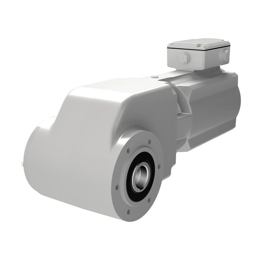
Page 9: Product Description
VLT® OneGearDrive® comprises a high-efficiency permanent magnet (PM) motor coupled to an optimized bevel gearbox. As part of the Danfoss VLT® FlexConcept®, the drive is an energy-efficient drive system that helps to optimize plant productivity and reduce energy costs. The VLT® FlexConcept® comprises the VLT® OneGearDrive® combined with a VLT® Decentral Drive FCD 302 or VLT®... - Page 10 220 V DC / 480 V AC [37] CSA/UL Without CSA/UL Only OneGearDrive® standard Standard for OneGearDrive® hygienic, optional for OneGearDrive® standard Only OneGearDrive® hygienic Use P2 also for P1 Option for OneGearDrive® standard only 10 | Danfoss A/S © 2020.12 AQ347551551757en-000101 / 130R0239...
-
Page 11: Mechanical Installation
Register a complaint immediately with the carrier if there is visible transport damage. Register a complaint immediately with the responsible Danfoss representative if there are visible defects or the delivery is incomplete. 4.4 Protection Rating The VLT®... -
Page 12: Mounting Procedure
4.9 Dimensions of the Metric Shaft and Disk. Adapt the key length according to the shaft length used. The dimensions shown could differ from the customer conditions and must potentially be changed by the customer. 12 | Danfoss A/S © 2020.12 AQ347551551757en-000101 / 130R0239... -
Page 13: Dimensions Of Assembly Kit For Imperial Shafts
The fixing screw and washer required depend on the length and size of the shaft. For further information, refer to the mounting arrangement (see 4.6 Mounting Arrangement). Shaft Disc d+0.2 [d+0.0078] edges cut b max b min Illustration 2: Axial Fastening Illustration 3: Maximum Eccentricity of the Conveyor Shaft Danfoss A/S © 2020.12 AQ347551551757en-000101 / 130R0239 | 13... -
Page 14: Dimensions Of The Metric Shaft And Disk
Set). Ensure that the torque arm does not create excessive constraining forces, for example due to the driven shaft running untrue. Excessive backlash can result in excessive shock torques in switching or reversing opera- tions. 14 | Danfoss A/S © 2020.12 AQ347551551757en-000101 / 130R0239... -
Page 15: Final Assembly
After installation, remove the eyebolt [1] and cover the hole with the plastic cap [2]. This ensures the hygienic features of a smooth surface. Illustration 6: Exchanging the Eyebolt with the Plastic Cap after Installation Eyebolt Danfoss A/S © 2020.12 AQ347551551757en-000101 / 130R0239 | 15... - Page 16 VLT® OneGearDrive® Operating Guide Mechanical Installation Plastic cap 16 | Danfoss A/S © 2020.12 AQ347551551757en-000101 / 130R0239...
-
Page 17: Electrical Installation
For systems with drives and rectifiers, the manufacturer’s electromagnetic compatibility information must also be consid- ered. The electromagnetic compatibility directive in accordance with IEC/EN 61800-3 is complied with given proper use and installa- tion of the VLT® OneGearDrive®. This is also true in combination with Danfoss drives and rectifiers. 5.2 Electrical Connection When connecting the motor, take note of the nameplate data, the connection diagram, and the relevant safety regulations and rules for the prevention of accidents. -
Page 18: Terminal Box Connection
Do not connect the VLT® OneGearDrive® directly to the supply. 5.4 CAGE CLAMP® Connection Illustration 9 shows the VLT® OneGearDrive® V210 with terminal box and the connection to the thermal protection. 18 | Danfoss A/S © 2020.12 AQ347551551757en-000101 / 130R0239... - Page 19 Operating Guides. Table 10: Connections T1 and T2 KTY 84-130 VLT® AutomationDrive FC 302 VLT® AutomationDrive FCD 302 KTY sensor 1 Analog input 54 Only if connected. Danfoss A/S © 2020.12 AQ347551551757en-000101 / 130R0239 | 19...
-
Page 20: Cleanconnect® Connection
For thermal protection, the built-in KTY sensor can be connected. Alternatively, the ETR function of the VLT AutomationDrive ® FC 302 or VLT® Decentral Drive FCD 302 can be used. 20 | Danfoss A/S © 2020.12 AQ347551551757en-000101 / 130R0239... -
Page 21: Commissioning
Ensure that the current draw in the loaded condition does not exceed the rated current indicated on the nameplate of the VLT® OneGearDrive® for any length of time (see 9.4 Speed/Torque Characteristics). After first commissioning, observe the VLT® OneGearDrive® for at least 1 hour to detect any unusual heat or noise. Danfoss A/S © 2020.12 AQ347551551757en-000101 / 130R0239 | 21... -
Page 22: Diagnostics
Heated grease from hollow shaft seal. The hol- Clean and check again after 1–2 weeks. Repeat low shaft seal is greased when it is mounted in the procedure if necessary. 22 | Danfoss A/S © 2020.12 AQ347551551757en-000101 / 130R0239... - Page 23 Oil level too high Check and correct the oil level using the oil check kit provided by Danfoss. Actual hollow shaft seal leakage. It has been Change the hollow shaft seal. confirmed that none of the other root causes apply.
-
Page 24: Maintenance, Decommissioning, And Disposal
8.2.1 Replacing the Brake and Rotor All work must only be carried out by qualified technical personnel on a stationary machine that has been protected against restart- ing. This also applies to auxiliary circuits. 24 | Danfoss A/S © 2020.12 AQ347551551757en-000101 / 130R0239... - Page 25 Close the brake cover and tighten the covering nuts [11] with tightening torque 2.3 Nm (20.36 in-lb). Always replace the plastic disks with new ones. Connect the brake to the rectifier (see 9.7.2.3 Connections). Danfoss A/S © 2020.12 AQ347551551757en-000101 / 130R0239 | 25...
-
Page 26: Inspection During Operation
Oil). 8.5.2 Oil Grade The filled oil type is specified on the nameplate. Danfoss uses food grade oils that comply with NSF H1. Do not mix different oil types as this may impair the characteristics of the oil. Contact Danfoss for further information on oil types. -
Page 27: Changing The Oil
Table 15: Oil Volume Oil volume [l (fl oz)] 2.2 (74.4) 3.1 (105) P1 is no longer available in the Danfoss DRIVECAT configurator. Use P2 also for P1 installations. 8.5.4 Changing the Oil N O T I C E DANGER OF BURNS The surface of the VLT®... -
Page 28: Decommissioning
8.7.2 Product Returns Danfoss products can be returned for disposal at no charge. A prerequisite for this is that they are free of deposits, such as oil, grease, or other types of contamination that hampers disposal. Furthermore, foreign materials or third-party components cannot be included with the returned product. -
Page 29: Specifications
The actual load depends strongly on local conditions, therefore the time period stated is only a guiding value. This period does not include any extension of the warranty. If disassembly is necessary before start-up, contact Danfoss Service. 9.2.1 Measures during Storage Turn the VLT®... -
Page 30: Technical Data: Permanent Magnet 3-Phase Synchronous Motor
9.4.1 Ratio i=31.13 i = 31.13 n [rpm] Maximum high starting torque, M (maximum Nominal torque, M 3 s,10 cycles/h) Typical operating range Torque in part load operation Illustration 15: Ratio i=31.13 30 | Danfoss A/S © 2020.12 AQ347551551757en-000101 / 130R0239... -
Page 31: Ratio
Maximum high starting torque, M Typical operating range Nominal torque, M Illustration 17: Ratio i=5.92 9.4.4 Speed/Torque Values Table 17: Speed/Torque Values Mn [Nm] [Nm] max [RPM] HST [Nm] 5.92 14.13 31.13 Danfoss A/S © 2020.12 AQ347551551757en-000101 / 130R0239 | 31... -
Page 32: General Specifications And Environmental Conditions
9.6.2 VLT® OneGearDrive® Standard with Torque Arm in Front Position (Optional) 92.5 [11.30] [4.80] [3.64] 78.5 [5.79] [2.91] [3.09] [1.38] [7.28] [0.24] [0.39] [4.84] Illustration 19: VLT® OneGearDrive® Standard with Torque Arm in Front Position (Optional) 32 | Danfoss A/S © 2020.12 AQ347551551757en-000101 / 130R0239... -
Page 33: Vlt® Onegeardrive® Hygienic
VLT® OneGearDrive®. If the plug is ® rotated, the cables could be damaged, causing a short circuit. Contact Danfoss Service if the plug is loose. 9.6.4 VLT® OneGearDrive® Hygienic with Torque Arm in Front Position (Optional) 78.5... -
Page 34: Shaft Dimensions
9.6.5.4 I1 Shaft 92.5 [3.64] 37.5 37.5 34.72 +0.2 [1.48] [1.48] [1.3669 +0.0078 ] 1.3 H13 1.422 H13 [0.05] [0.056] 73.5 73.5 [2.89] [2.89] [7.28] Illustration 26: Steel/Stainless Steel I1 Shaft 34 | Danfoss A/S © 2020.12 AQ347551551757en-000101 / 130R0239... -
Page 35: I2 Shaft
The torque arm set consists of the torque arm (see Illustration 29) and the mounting set (see Illustration 30). 207.5 [8.17] 185+0.2 [7.28] [0.59] [0.99] Ø11 [0.43] A - A Illustration 29: Torque Arm Danfoss A/S © 2020.12 AQ347551551757en-000101 / 130R0239 | 35... -
Page 36: Mechanical Brake
Only use the original Danfoss or comparable mounting set to mount the VLT® OneGearDrive® to the conveyor. The mounting equipment used must ensure the same degree of flexibility as the original Danfoss mounting set. Do not screw the torque arm directly onto the conveyor frame. -
Page 37: Technical Data
10 (88.5) 9.7.2.2 Dimensions [21.50] Illustration 31: Dimensions of VLT® OneGearDrive® with Mechanical Brake Option 9.7.2.3 Connections Illustration 32 shows the cage clamp and the connections to the VLT® AutomationDrive FC 302. Danfoss A/S © 2020.12 AQ347551551757en-000101 / 130R0239 | 37... - Page 38 Frequency converter Output relay U V W Command circuit Output Freewheeling contactor diode input Brake supply voltage* OneGearDrive with brake option Illustration 33: Example of Connecting the Mechanical Brake to the Drive 38 | Danfoss A/S © 2020.12 AQ347551551757en-000101 / 130R0239...
-
Page 39: Accessories
The connection and use of the mechanical brake have been tested and released with VLT® AutomationDrive FC 302 and VLT® De- central Drive FCD 302. Any other drive may require a different connection. Contact Danfoss Service for further information. For in- formation about parameter setting and programming when using VLT®... -
Page 40: Appendix
Permanent magnet motor Revolutions per minute 10.2 Conventions • Numbered lists indicate procedures. • Italicized text indicates: Cross-reference Link Footnote Parameter name or group • All dimension drawings are in [mm (in)]. 40 | Danfoss A/S © 2020.12 AQ347551551757en-000101 / 130R0239... - Page 41 Technical data....................30 Terminal box....................17 Torque arm set....................35 Inductivity....................... 30 Torque mounting set.................. 35 Inertia........................30 Torque restraint.................... 14 Inspection during operation..............26 Trademarks......................6 Inspection on receipt.................. 11 Transport......................11 Installation Troubleshooting................... 22 Mechanical.....................11 Danfoss A/S © 2020.12 AQ347551551757en-000101/130R0239 | 41...
- Page 42 Canadian test and certification mark. Cage clamp Wire retention method without using special tools in the terminal box. CleanConnect EHEDG certified connection from Danfoss with a stainless steel connector. EHEDG European Hygienic Engineering and Design Group. ExtensionBox Optional part for VLT® OneGearDrive® that increases the output torque.
- Page 43 Terminal box Connection cage for the VLT® OneGearDrive®. Torque arm set Accessory for the VLT® OneGearDrive® that includes a torque arm and a mounting-set. Maximum ambient temperature specified. Underwriters Laboratories. Danfoss A/S © 2020.12 AQ347551551757en-000101/130R0239 | 43...
- Page 44 Danfoss can accept no responsibility for possible errors in catalogs, brochures and other printed material. Danfoss reserves the right to alter its products without notice. This also applies to products already on order provided that such alterations can be made without subsequential changes being necessary in specifications already agreed. All trademarks in this material are property of the respective companies.
Need help?
Do you have a question about the VLT OneGearDrive and is the answer not in the manual?
Questions and answers