Table of Contents
Advertisement
Quick Links
Advertisement
Table of Contents

Related Manuals for Danfoss MP1


Summary of Contents for Danfoss MP1
- Page 1 Service Manual MP1 Axial Piston Motors Size 20/24 www.danfoss.com...
- Page 2 Updated Part Option for Speed and Temperature Sensor 0104 March 2020 Changed number of the shuttle shifts to 4 bar 0103 December 2019 Changed torque units from N•m [lbf•ft] to N•m [lbf•in] 0102 December 2019 First edition 0101 © Danfoss | November 2020 AX323657269473en-000104...
-
Page 3: Table Of Contents
Hydrostatics Servicing Overview..............................5 Safety Precautions....................................5 Unintended Machine Movement............................5 Flammable Cleaning Solvents..............................5 Fluid Under Pressure..................................5 Personal Safety.....................................5 General Information MP1 Motors Overview..................................6 MP1 Motor Features..................................6 System Diagram....................................7 Schematic Diagram..................................8 Technical Specifications Design Specifications..................................9 Technical Data....................................9 Operating Parameters..................................9 Fluid Specifications..................................10 System Design Parameters Determination of Nominal Motor Size........................... - Page 4 Loop Flushing Valve Removal..............................30 Inspect the Components............................... 30 Install the Loop Flushing Valve............................30 Anti-cavitation Valve..................................31 Remove the Anti-cavitation Valve (Supply Check Relief Valve)................31 Inspect the Components............................... 31 Install the Anti-cavitation Valve............................31 Torque Chart Fasteners and Torque...................................32 © Danfoss | November 2020 AX323657269473en-000104...
-
Page 5: Hydrostatics Servicing Overview
MP1 Motor Introduction Hydrostatics Servicing Overview This manual includes information on installation, maintenance, and minor repair of the MP1 motor. It includes a description of the unit and its individual components, troubleshooting information, and minor repair procedures. Performing minor repairs may require the unit to be removed from the vehicle/machine. Thoroughly clean the unit before beginning maintenance or repair activities. -
Page 6: General Information
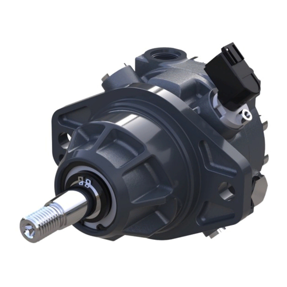
General Information MP1 Motors Overview The MP1 motor is a fixed displacement axial piston motor intended for closed and open circuit medium power applications. These motors are designed primarily to be combined with other products in closed and open circuit systems to transfer and control hydraulic power. -
Page 7: System Diagram
Working Loop (High Pressure) P400619 The system diagram above shows the MP1 motor in a simple closed-loop hydrostatic propel application. The motor is driven by a variable displacement pump. The motor shows an integral loop flushing option that will remove heat and contaminants from the main loop. -
Page 8: Schematic Diagram
Similarly, if the anti- cavitation and shock valve is oriented in the reverse position, the direction of rotation will be clockwise. Thus, pressurized fluid flow path is from port B through port A. © Danfoss | November 2020 AX323657269473en-000104... -
Page 9: Technical Specifications
380 [5429] Rated 2 [29] Case pressure bar [psi] Maximum 6 [87] At Maximum speed, system minimum low pressure is 18 bar. Applied pressures above maximum working pressure requires Danfoss application approval. © Danfoss | November 2020 AX323657269473en-000104 | 9... -
Page 10: Fluid Specifications
Intermittent=Short term t <1 min per incident and not exceeding 2 % of duty cycle based load-life. Cold start = Short term t < 3 min, p < 50 bar [725 psi], n < 1000 min (rpm) At the hottest point, normally case drain port. 10 | © Danfoss | November 2020 AX323657269473en-000104... -
Page 11: System Design Parameters
= Outlet pressure bar [psi] = Inlet pressure bar [psi] ∆p = p (system pressure) bar [psi] η = Volumetric efficiency η = Mechanical-hydraulic efficiency η = Motor total efficiency (η • η © Danfoss | November 2020 AX323657269473en-000104 | 11... -
Page 12: Part Options
The hydraulic circuit of an MP1 motor with loop flushing option is shown below. The MP1 motor loop flushing design is a simple spring centered shuttle spool with an orifice notch. - Page 13 System pressure _ low side [dbar] P400656 When a MP1 pump is used with an external loop flushing shuttle valve, ensure that the charge setting of the pump matches the setting of the loop flushing shuttle valve. Contact your Danfoss representative for the availability of additional charge relief settings.
-
Page 14: Anti-Cavitation And Shock Valve
Flushing & Anti- cavitation Clockwise (CW) MD1/MD2/SD1/SD2 Counterclockwise (CCW) MC1/MC2/SC1/SC2 Master Model Code Anti cavitation and shock valve, Port B High Pressure, Clockwise rotation Shock valve Anti-cavitation valve P400636 Anti-cavitation and shock valve P400658 14 | © Danfoss | November 2020 AX323657269473en-000104... -
Page 15: Speed And Temperature Sensor
P400660 Speed and Temperature Sensor MP1 motors are available with an optional speed and temperature sensor. This hall-effect pulse pick-up is located in the motor housing. The sensor accepts supply voltage and outputs a digital pulse signal in response to the speed of the cylinder block. The output changes its high/low state as the target teeth pass by the sensor's face. -
Page 16: Sensor Position
25 mA At supply voltage Max. required supply current – – 50 mA Max. output current NPN & PNP Push-Pull amplifier Operation mode -40°C = 2.318V – 100°C = 0.675V Temperature signal 16 | © Danfoss | November 2020 AX323657269473en-000104... -
Page 17: Speed Sensor 7 - 32 V
Color of connector For more information, see Speed and Temperature Sensor, Technical Information, BC152886482203. Output Pulses The expected number of output pulses per revolution is shown below. The number of pulses (per rev) © Danfoss | November 2020 AX323657269473en-000104 | 17... -
Page 18: Operating Parameters
Smooth operation and output torque ripple determine the acceptable low speed operating condition. Generally Danfoss axial piston motors will operate smoothly down to 150 rpm. In some instances, it is possible to operate smoothly at less than 150 rpm, but performance must be verified for the specific application. -
Page 19: Case Pressure
The minimum temperature relates to the physical properties of component materials. Size heat exchangers too keep the fluid within these limits. Danfoss recommends testing to verify that these temperature limits are not exceeded. -
Page 20: Pressure Measurements
L1, L2 3/4-16 UNF / M18 x 1.5 Case drain 10 [100] 7/8-14 UNF / M22 x 1.5 System pressure 500 [7250] 7/8-14 UNF / M22 x 1.5 System pressure 500 [7250] 20 | © Danfoss | November 2020 AX323657269473en-000104... -
Page 21: Sae B Flange Port Locations And Specifications
L1, L2 3/4-16 UNF / M18 x 1.5 Case drain 10 [100] 7/8-14 UNF / M22 x 1.5 System pressure 500 [7250] 7/8-14 UNF / M22 x 1.5 System pressure 500 [7250] © Danfoss | November 2020 AX323657269473en-000104 | 21... -
Page 22: Cartridge Flange Port Locations And Specifications
L1, L2 3/4-16 UNF / M18 x 1.5 Case drain 10 [100] 7/8-14 UNF / M22 x 1.5 System pressure 500 [7250] 7/8-14 UNF / M22 x 1.5 System pressure 500 [7250] 22 | © Danfoss | November 2020 AX323657269473en-000104... -
Page 23: Fluid And Filter Maintenance
Replace all fluid lost during filter change. Warning Hydraulic fluid contains hazardous material. Avoid contact with hydraulic fluid. Always dispose of used hydraulic fluid according to state, and federal environmental regulations. Never reuse hydraulic fluid. © Danfoss | November 2020 AX323657269473en-000104 | 23... -
Page 24: Initial Start-Up Procedures
To ensure the pump and motor stay filled with oil, install case drain lines into the upper most case drain ports. Attention Never start the prime mover unless the motor and pump housings are filled completely with clean hydraulic fluid. 24 | © Danfoss | November 2020 AX323657269473en-000104... -
Page 25: Install Charge Pressure Gauge
6. Continue to cycle slowly between forward and reverse for at least five minutes. 7. Shut down prime mover. 8. Remove gauges. Replace plugs at the gauge ports. 9. Check reservoir level. Add filtered fluid if needed. The motor/transmission is now ready for operation. © Danfoss | November 2020 AX323657269473en-000104 | 25... -
Page 26: Troubleshooting
Viscosity above acceptable limits will result in cavitation that would lead to Replace hydraulic oil with appropriate fluid for about limits. system noise. operating conditions. Refer to publication 5200L0463 for information on fluid selection. 26 | © Danfoss | November 2020 AX323657269473en-000104... -
Page 27: Minor Repair
Carefully drive a small sheet-metal screw into the shaft seal to facilitate removal. Be careful not to damage the bearing below the seal. Attach a slide hammer or appropriate puller to the screw head and pull to remove the seal. D210 D200 D150 D140 D130 © Danfoss | November 2020 AX323657269473en-000104 | 27... -
Page 28: Shaft Seal And Dust Seal Assembly
7. If a dust seal is used, install dust seal (D200). 8. If a dust seal is used, use snap ring pliers to install the retaining ring (D210) to retain the dust seal. D210 *D200 D150 D140 *D130 D120 28 | © Danfoss | November 2020 AX323657269473en-000104... -
Page 29: Speed Sensor
1. Lubricate and install new O-ring (QK301). 2. Install speed sensor (K300). 3. Install speed sensor cover (K350), if used. 4. Install screw (K310) using a 5 mm internal hex wrench with torque to 8 N•m [71 lbf•in]. © Danfoss | November 2020 AX323657269473en-000104 | 29... -
Page 30: Loop Flushing Valve
3. Carefully install centering springs (E210 and E260). 4. Install new O-rings for plugs (E400 and E410). 5. Using a 19 mm or 3/4 in wrench, torque plugs (E400 and E410) to 35 N•m [310 lbf•in]. 30 | © Danfoss | November 2020 AX323657269473en-000104... -
Page 31: Anti-Cavitation Valve
4. Install the plug (either E400 or E410) and a new O-ring on the same side as the supply check relief valve using a 22 mm wrench. Torque to 78 N•m [690 lbf•in]. E400 E310 E300 Option codes: SC1, SC2, MC1, MC2 E350 E360 E410 Option codes: SD1, SD2, MD1, MD2 © Danfoss | November 2020 AX323657269473en-000104 | 31... -
Page 32: Torque Chart
MP1M Fasteners and Torque Item Fastener Torque K310 Screw 8 N•m [71 lbf•in] E400 and E410 (loop flushing) Plug 35 N•m [310 lbf•in] E400 and E410 (anti-cavitation) Plug 78 N•m [690 lbf•in] 32 | © Danfoss | November 2020 AX323657269473en-000104... - Page 33 Phone: +86 21 2080 6201 Danfoss can accept no responsibility for possible errors in catalogues, brochures and other printed material. Danfoss reserves the right to alter its products without notice. This also applies to products already on order provided that such alterations can be made without subsequent changes being necessary in specifications already agreed.
Need help?
Do you have a question about the MP1 and is the answer not in the manual?
Questions and answers