Table of Contents
Advertisement
Quick Links
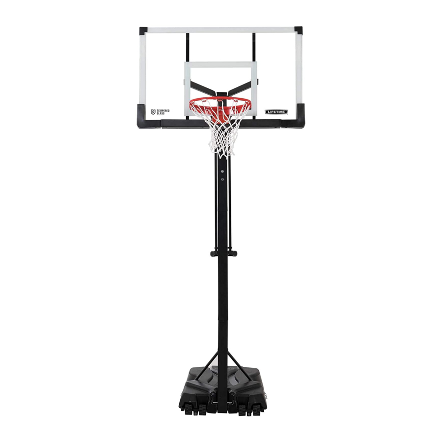
MAMMOTH SERIES
PORTABLE BASKETBALL SYSTEM
MODEL 90734
BEFORE ASSEMBLY:
• Before you start, decide how you would like to fi ll
your base (sand is recommended).
• Assembly should take 3 adults about 3-4
hours to complete.
Save this instruction in the event that the manufacturer has
to be contacted for replacement parts.
TOOLS REQUIRED*
*not included unless otherwise indicated
3/8", 1/2", 9/16", 3/4"
(2)
(1)
(1)
QUESTIONS?
CONTACT LIFETIME CUSTOMER SERVICE:
Call: 1-800-225-3865
7:00 am-5:00 pm (Monday-Friday) MST
and 9:00 am-1:00 pm Saturday MST
(English, French, Spanish)
1/2"
(2)
(1)
(1)
(1)
(1)
(1)
Live Chat:
www.lifetime.com/customerservice
ASSEMBLY INSTRUCTIONS
™
(1)
3/16"
(2, included)
400 lb (181 kg)
For Customer Service in Mainland
Europe and the United Kingdom,
E-mail: cs@lifetimeproducts.eu
TABLE OF CONTENTS
Icon Legend................................2
Notices....................................3
Pole Assembly.............................4
Pole to Base Assembly.................9
Backboard to Rim Assembly.......17
Backboard to Pole Assembly.......25
Handle Assembly.......................31
Final Assembly..........................39
Maintenance Instructions..........44
Warning Sticker........................45
Registration..........................46
Warranty...............................47
Model Number: 90734
Product ID:
Advertisement
Table of Contents

Related Manuals for Lifetime MAMMOTH Series


Summary of Contents for Lifetime MAMMOTH Series
-
Page 1: Table Of Contents
(2, included) Warning Sticker......45 Registration......46 Warranty.......47 400 lb (181 kg) Model Number: 90734 QUESTIONS? CONTACT LIFETIME CUSTOMER SERVICE: Product ID: Call: 1-800-225-3865 For Customer Service in Mainland Live Chat: Europe and the United Kingdom, www.lifetime.com/customerservice 7:00 am–5:00 pm (Monday–Friday) MST E-mail: cs@lifetimeproducts.eu... -
Page 2: Icon Legend
ICON LEGEND • Indicates special heed should be taken when reading. • Indicates the parts to be used for a section. • Indicates no parts required for a specifi c section. • Indicates the hardware to be used for a section. •... -
Page 3: Notices
WARNINGS & NOTICES SAFETY INSTRUCTIONS FAILURE TO FOLLOW THESE WARNINGS MAY RESULT IN SERIOUS INJURY OR PROPERTY DAMAGE AND WILL VOID WARRANTY. Owner must ensure that all players know and follow these rules for safe operation of the system. To ensure safety, do not attempt to assemble this product without following the instructions carefully. Check entire box and inside all packing material for parts and/or additional instruction material. -
Page 4: Pole Assembly
N’accrochez rien au manche, à l’anneau, elevación, ya que esto puede dañar el sistema y anular la garantía. au panneau ni aux leviers sous peine d’endommager l’équipement et d’annuler la garantie. Lifetime Products, Inc., Clearfield, UT 84016 1-800-225-3865 www.lifetime.com 11/23/2015... - Page 5 N’accrochez rien au m au panneau ni aux leviers sous peine d’endom et d’annuler la garantie. learfield, UT 84016 www.lifetime.com 11/23/2015 -3865 Warning Sticker Alignment Sticker Small Holes...
- Page 6 SECTION 1 (CONTINUED) TOOLS AND HARDWARE REQUIRED • Make sure the Pole Alignment Stickers are on the same side of the Pole assembly as the Pole Bracket. Slide the Top Pole (ALH) onto the Middle Pole (ALF) as shown. Alignment sticker ATTENTION: THIS STEP CANNOT BE REVERSED! •...
- Page 7 SECTION 1 (CONTINUED) TOOLS AND HARDWARE REQUIRED • Slide the Middle Pole (ALF) onto the Bottom Pole (ALE) as shown. Make sure the Alignment Sticker on the Bottom Pole faces the same direction as the stickers on the Top and Middle Poles. The off-center holes in the Bottom Pole should be oriented as shown, away from the side of the pole with the Pole Bracket (ALL).
- Page 8 SECTION 1 (CONTINUED) TOOLS AND HARDWARE REQUIRED ABZ (x4) • After the poles have been seated, insert two Self-Drilling Screws (ABZ) into the back of the pole as shown. These screws are designed to drill through the metal of the underlying pole section. ABZ (x2) ABZ (x2) •...
-
Page 9: Pole To Base Assembly
POLE TO BASE ASSEMBLY HARDWARE REQUIRED Hardware Blister Pack DRZ (x1) BTS (x1) ABH (x4) AOH (x6) AAO (x2) GDI (x2) ABD (x4) CKV (x8) EEO (x2) AAM (x2) Hardware Bag CNC (x2) PARTS REQUIRED Metal Parts (Shown at 20% Actual Size) 29.75”... - Page 10 POLE TO BASE ASSEMBLY PARTS REQUIRED (CONTINUED) Metal Parts (Shown at 10% Actual Size) ALI (x2) GDG (x2) GDH (x2) GDF (x1) Plastic Parts AJM (x1) AMU (x4) TOOLS REQUIRED 3/16” 9/16” 1/2” (≈5 mm) (≈15 mm) (≈13 mm) (2, included)
- Page 11 SECTION 2 (CONTINUED) TOOLS AND HARDWARE REQUIRED • Slide one end of the Long Axle (GDD) through two Wheels (AMU) and one Base Frame Tube (GDG). Position the parts as shown, with one Wheel on each side of the Base Frame Tube. •...
- Page 12 SECTION 2 (CONTINUED) TOOLS AND HARDWARE REQUIRED 9/16” (≈15 mm) ABH (x4) AOH (x4) CKV (x8) • Secure the Outer Support Tubes (GDH) to the Base Frame Tubes (GDG) as shown.
- Page 13 SECTION 2 (CONTINUED) TOOLS AND HARDWARE REQUIRED 9/16” (≈15 mm) GDI (x2) AOH (x2) • Secure the Cross Brace (GDF) to the Base Support Tubes. Use a rubber mallet, if necessary, to tap the bolts into place. • Make sure the Brackets on the Cross Brace (GDF) are angled as shown.
- Page 14 SECTION 2 (CONTINUED) TOOLS AND HARDWARE REQUIRED • Slide the Small Axle (AJE) into the Bottom Pole (ALE) in the location shown. • Raise the Pole Assembly until the Small Axle pops • Carefully rest the system on its side. into place on the Base.
- Page 15 SECTION 2 (CONTINUED) TOOLS AND HARDWARE REQUIRED 1/2” (≈13 mm) CNC (x2) AAO (x2) AAM (x2) ABD (x4) • While on it’s side, attach the fl attened end of the Pole Brace (ALI) to the Base (AJM) with the hardware shown. Install the Chain (CNC) between the Washer and the Pole Brace.
- Page 16 SECTION 2 (CONTINUED) TOOLS AND HARDWARE REQUIRED 3/16” (≈5 mm) 1/2” (≈13 mm) DRZ (x1) BTS (x1) 2.11 2.12 • Attach the Pole Braces (ALI) to the Bottom Pole (ALE) • Tighten the hardware from this section before with the hardware shown. continuing with the assembly.
-
Page 17: Backboard To Rim Assembly
BACKBOARD TO RIM ASSEMBLY HARDWARE REQUIRED Hardware Blister Pack 5 9/16” ABB (x2) ANL (x1) AAX (x1) ANJ (x4) ANM (x2) ADX (x2) ANK (x4) ABD (x4) ABK (x4) ANN (x2) BGZ (x1) PARTS REQUIRED Metal Parts ALX (x1) AJI (x1) - Page 18 BACKBOARD TO RIM ASSEMBLY PARTS REQUIRED Metal Parts BPZ (x1) BQA (x1) AMK (x1) ALY (x1) AMA (x1) ANO (x1) AMC (x1) AMB (x1) Plastic Parts BGY (x1) TOOLS REQUIRED 1/2” 9/16” 3/4” (≈13 mm) (≈15 mm) (≈19 mm)
- Page 19 SECTION 3 (CONTINUED) TOOLS AND HARDWARE REQUIRED 1/2” (≈13 mm) ANJ (x2) ABK (x2) ABD (x2) • Lay the Backboard (AJI) face up with the Rim holes exposed over the edge of a table. Place the Rim Impact Spacer (BGY) in the Backboard. Add the Left and Right Rim Housings (AMC & AMB) on top of the Rim Impact Spacer and slide the hardware shown into place.
- Page 20 SECTION 3 (CONTINUED) TOOLS AND HARDWARE REQUIRED 1/2” (≈13 mm) ANJ (x2) ABK (x2) ABD (x2) • Secure the Rim Adapter Plate (ALY) to the Backboard (AJI) by using the hardware as shown. • Only fi nger-tighten this hardware for now.
- Page 21 SECTION 3 (CONTINUED) TOOLS AND HARDWARE REQUIRED 5 9/16” 3/4” (≈19 mm) ANL (x1) ANK (x2) AAX (x1) • Slide the end of the Rim Pin (BPZ) into the Rim (ALX) and through the Eye Bolt (BQA) in the location indicated. Attach the Rim to the Rim Housing using the hardware shown, making sure the Nylon Washers (ANK) rest between the Rim and the Rim Housing.
- Page 22 SECTION 3 (CONTINUED) TOOLS AND HARDWARE REQUIRED 1/2” (≈13 mm) ANM (x2) ABB (x2) ANK (x2) • Securely tighten the hardware from steps 3.1 and 3.2. 1/2” (≈13 mm) 1/2” (≈13 mm) • Slide the Spring Holder Clevis (AMK) onto the Eye Bolt (BQA) and secure with the hardware shown. •...
- Page 23 SECTION 3 (CONTINUED) TOOLS AND HARDWARE REQUIRED 9/16” (≈15 mm) ANO (x1)* ANN (x2) • Washer (ANO) is found BGZ (x1) in the Rim Kit. • Slide the Compression Spring (BGZ) onto the Eye Bolt (BQA), and secure with the hardware shown. Tighten the 3/8” Zinc Nuts (ANN) to adjust the rim tension.
- Page 24 SECTION 3 (CONTINUED) TOOLS AND HARDWARE REQUIRED ADX (x2) • Attach the Rim Cover Plate (AMA) to the Rim.
-
Page 25: Parts Identifier
N’accrochez rien au manche, à l’anneau, au panneau ni aux leviers sous peine d’endommager l’équipement et d’annuler la garantie. Lifetime Products, Inc., Clearfield, UT 84016 www.lifetime.com 11/23/2015 # 1171370... - Page 26 PARTS IDENTIFIER Metal Parts BPZ (x1) ALY (x1) BQA (x1) ANO (x1) AMA (x1) AMK (x1) AMC (x1) AMB (x1) ALC (x1) ALS (x2) GDG (x2) GDH (x2) GDF (x1) ALI (x2) 29.75” (75.6 cm) GDD (x1) 7” (17.8 cm) AJE (x1)
- Page 27 PARTS IDENTIFIER Plastic Parts AKI (x1) AJM (x1) ALM (x1) FIR (x1) FIQ (x1) AMU (x4) GFL (x1) AKZ (x1) AEF (x1) BGY (x1) HARDWARE REQUIRED...
- Page 28 PARTS IDENTIFIER This page intentionally left blank...
-
Page 29: Backboard To Pole Assembly
BACKBOARD TO POLE ASSEMBLY HARDWARE REQUIRED Hardware Blister Pack ANQ (x2) ABN (x6) AOR (x4) ANU (x2) ANP (x1) GDO (x4) GOS (x4) ANK (x2) ANS (x8) GDN (x4) ABP (x2) ADM (x2) GDM (x2) PARTS REQUIRED Metal Parts Plastic Part AKE (x1) ALM (x1) BGO (x2) - Page 30 SECTION 4 (CONTINUED) TOOLS AND HARDWARE REQUIRED 3/16” (≈5 mm) GDN (x2) GDO (x2) GOS (x2) ABN (x2) GDM (x1) • Secure one Bolt (GDN) and Washer (GDO) to a Coupler Pin (GDM) at one end. • Attach the Lower Extension Arms (AKE) to the Top Pole (ALH) with the hardware shown. If necessary, use a Rubber Mallet to tap the Coupler Pin Assembly through the holes.
- Page 31 SECTION 4 (CONTINUED) TOOLS AND HARDWARE REQUIRED 3/16” (≈5 mm) GDN (x2) GDO (x2) ABN (x2) GOS (x2) GDM (x1) • Secure one Bolt (GDN) and Washer (GDO) to a Coupler Pin (GDM) at one end. • Attach the Upper Extension Arms (BGO) to the Top Pole (ALH) with the hardware shown. If necessary, use a Rubber Mallet to tap the Coupler Pin Assembly into place.
- Page 32 SECTION 4 (CONTINUED) TOOLS AND HARDWARE REQUIRED 3/4” (≈19 mm) ANQ (x2) ABP (x2) ANP (x1) AOR (x2) CAUTION: HAVE ONE ADULT HOLD THE BACKBOARD IN PLACE UNTIL ASSEMBLY HAS BEEN COMPLETED! • Lay the Backboard and Rim assembly next to the Pole assembly. Rest the Rim on cardboard to prevent scratching, then secure the Lower Extension Arms (AKE) to the Backboard (AJI) with the hardware shown.
- Page 33 SECTION 4 (CONTINUED) TOOLS AND HARDWARE REQUIRED 3/4” (≈19 mm) ANU (x2) ANK (x2) ABN (x2) AOR (x2) ADM (x2) • Attach both Upper Extension Arms (BGO) to the Backboard (AJI) with the hardware shown. • Tighten the Nuts (ADM) until they are fl ush with the end of the Bolts.
- Page 34 SECTION 4 (CONTINUED) TOOLS AND HARDWARE REQUIRED ANS (x8) • Insert Nylon Plugs (ANS) into the locations indicated on • Insert the Pole Cap (ALM) into the Top Pole. the back of the Backboard.
-
Page 35: Handle Assembly
HANDLE ASSEMBLY HARDWARE REQUIRED Hardware Blister Pack GOX (x1) GDN (x10) GDO (x10) ABN (x4) GOU (x1) ACZ (x2) GDP (x1) GDX (x1) GDM (x1) AAO (x1) GDQ (x1) GDZ (x2) GDY (x1) PARTS REQUIRED ALS (x2) AKI (x1) GFL (x1) ALC (x1) TOOLS REQUIRED 3/16”... - Page 36 SECTION 5 (CONTINUED) TOOLS AND HARDWARE REQUIRED 1/2” (≈13 mm) AAO (x1) GOX (x1) • Align the holes in the Gas Spring (GFL) with the holes in the Pole Bracket (ALL), and attach the Gas Spring assembly to the Pole Bracket with the hardware shown. •...
- Page 37 SECTION 5 (CONTINUED) TOOLS AND HARDWARE REQUIRED 3/16” (≈5 mm) GOU (x1) GDN (x2) GDO (x2) ABN (x2) • Secure one Bolt (GDN) and Washer (GDO) to a Coupler Pin (GOU) at one end. • Secure the Handle (AKI) to the Pole. •...
- Page 38 SECTION 5 (CONTINUED) TOOLS AND HARDWARE REQUIRED 3/16” (≈5 mm) GDN (x4) GDZ (x2) GDO (x4) • Secure a Bolt (GDN) and a Washer (GDO) at one end of both Coupler Pins (GDZ). • Position one of the Lifter Arms (ALS) as shown. Slide the •...
- Page 39 SECTION 5 (CONTINUED) TOOLS AND HARDWARE REQUIRED • Secure the Padlock (ALC) in the location shown to lock the adjustment mechanism. This will keep the actuator in the proper position for the next assembly step. ALC (x1)
- Page 40 SECTION 5 (CONTINUED) TOOLS AND HARDWARE REQUIRED 3/16” (≈5 mm) GDX (x1) GDN (x2) ACZ (x2) GDO (x2) • Secure one Bolt (GDN) and Washer (GDO) to a Coupler Pin (GDX) at one end. • Slide the Coupler Pin Assembly through the Lifter Arms and the Gas Spring, adding Plastic Spacers (ACZ) in the locations shown.
- Page 41 SECTION 5 (CONTINUED) TOOLS AND HARDWARE REQUIRED GDQ (x1) GDP (x1) 5.10 • Slide the Actuator Clip (GDP) onto the Handle Bracket. Pull the tabs on each side of the Clip to bypass the slots in the bracket as you slide it up against the plastic Handle. Hold the Clip as you perform the next step. Notched side must face up towards the Slots in the Handle...
- Page 42 SECTION 5 (CONTINUED) TOOLS AND HARDWARE REQUIRED 3/16” (≈5 mm) GDM (x1) GDY (x1) GDN (x2) GDO (x2) ABN (x2) 5.12 • Secure one Bolt (GDN) and Washer (GDO) to a Coupler Pin (GDM) at one end. 5.13 • Secure the Lifter Arms (ALS) to the Lower Extension Arms (AKE) using the hardware shown. Make sure the Plastic Spacers (ABN) are placed between the Lifter Arms and the plates on the Extension Arms.
-
Page 43: Final Assembly
FINAL ASSEMBLY HARDWARE REQUIRED Hardware Blister Pack AQQ (x2) CHQ (x2) AAF (x2) PARTS REQUIRED AEF (x1) FIQ (x1) FIR (x1) AKZ (x1) AKP (x1) TOOLS REQUIRED 9/16” (≈15 mm) (x1) 400 lb (x1) (x1) (x1) (181 kg) (x1) (x1) - Page 44 SECTION 6 (CONTINUED) TOOLS AND HARDWARE REQUIRED 400 lb (181 kg) • Press the Base Plug (AEF) into the base in the location shown. Three adults are required to complete assembly. To prevent serious injuries, the Pole should be held down by one adult at all times while the Base is being fi...
- Page 45 SECTION 6 (CONTINUED) TOOLS AND HARDWARE REQUIRED Three adults are required to complete assembly. To prevent serious injuries, the pole should be held down by one adult at all times while the base is being fi lled. • Have three adults stand the system upright. WARNING The assembled system is very heavy.
- Page 46 SECTION 6 (CONTINUED) TOOLS AND HARDWARE REQUIRED • Attach the Net (AKZ) to the Rim (ALX). • Raise the backboard until the top of the rim measures 10 feet from the playing surface. Apply the Height Adjustment Sticker (AKP) onto the Gas Spring (GFL), lining up the edge of the Gas Spring Cover with the 10-foot mark on the sticker. Press the sticker into place while carefully removing the rest of the backing.
- Page 47 SECTION 6 (CONTINUED) TOOLS AND HARDWARE REQUIRED (x1) 9/16” CHQ (x2) (≈15 mm) AQQ (x2) AAF (x2) (x1) • Pull out the end links of the Chains (CNC) so they are away from the sides of the base. Mark the location of the last links in the chain and use a hammer drill to drill a hole 1/2 inch (13 mm) in diameter and 1 1/2 inches (39 mm) deep in the concrete in each spot.
-
Page 48: Maintenance Instructions
MAINTENANCE INSTRUCTIONS The life of your basketball system depends on many variables. The climate, exposure to corrosives such as salt, pesticides, or herbicides, and excessive use or misuse can all contribute to pole failure, which may cause property damage or personal injury. Check your basketball system frequently for loose hardware, excessive wear, and signs of corrosion. -
Page 49: Warning Sticker
N’accrochez rien au manche, à l’anneau, elevación, ya que esto puede dañar el sistema y anular la garantía. au panneau ni aux leviers sous peine d’endommager l’équipement et d’annuler la garantie. Lifetime Products, Inc., Clearfield, UT 84016 www.lifetime.com # 1180194 1-800-225-3865... -
Page 50: Registration
. And you can rest assured that Lifetime will not sell or provide your personal data to other third parties, or allow them to use your personal data for their own purposes. We invite you to read our privacy policy at www.lifetime.com REGISTER today! - Page 51 3. This warranty is nontransferable and is expressly limited to the repair or replacement of defective product. If the product is defective within the terms of this warranty, Lifetime Products, Inc. will repair or replace defective parts at no cost to the purchaser.
- Page 52 7:00 am–5:00 pm (M–F) MST and 9:00 am–1:00 pm Saturday MST ® AMÉLIORER L’ACHAT LIFETIME EN AJOUTANT DES ACCESSOIRES OU D’AUTRES PRODUITS ® Pour acheter des accessoires ou des autres produits Lifetime , visiter le : www.lifetime.com (Anglais seulement) Ou composer le 1-800-424-3865 Du lundi au vendredi de 7 h à...
Need help?
Do you have a question about the MAMMOTH Series and is the answer not in the manual?
Questions and answers