Table of Contents
Advertisement
Quick Links
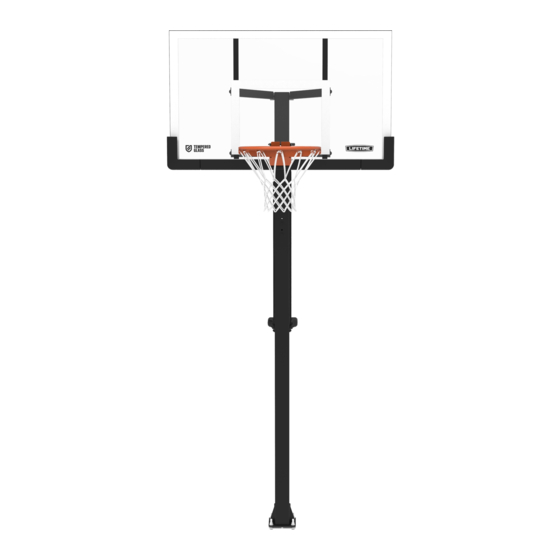
MAMMOTH
BOLT-DOWN, BASKETBALL SYSTEM
MODEL 91198
BEFORE ASSEMBLY:
• Requires at least 1040 lb (472 kg) of concrete
mix to fi ll a volume of 7.78 ft
• Requires at least 3 days (72 hours) for
concrete to cure, plus 3-4 hours to
complete assembly steps
• At least 3 people recommended for setup
TOOLS REQUIRED
Carpenter's Level
1/2" (x2)
3/16"
(x2, included)
QUESTIONS?
Dial 1-800-225-3865
7:00 am-5:00 pm (M-F) MST
and 9:00 am-1:00 pm (Sat) MST
LIFT
®
(0.22 m
)
3
3
Shovel
3/4" (x1)
5/16"
(x1, included)
CONTACT LIFETIME® CUSTOMER SERVICE:
Live Chat:
www.lifetime.com/customerservice
(Click on the "LIVE CHAT" tab)
ASSEMBLY INSTRUCTIONS
Tape Measure
Concrete Mix
(80 lb bag x13)
9/16" (x2)
Electric Drill
Rubber Mallet
For Customer Service in Mainland Europe and
the United Kingdom,
E-mail: cs@lifetimeproducts.eu
TABLE OF CONTENTS
Icon Legend..................................................................2
Warnings & Notices......................................................3
Initial Setup..................................................................4
Pole Assembly..............................................................7
Extension Arm Assembly...........................................10
Handle Assembly........................................................15
Backboard-to-Rim Assembly.....................................25
Backboard-to-Pole Assembly.....................................32
Final Assembly...........................................................36
Maintenance Instructions..........................................41
Registration..............................................................42
Warning Sticker..........................................................43
Warranty...................................................................47
Model Number: 91198
Product ID:
Advertisement
Table of Contents

Related Manuals for Lifetime MAMMOTH LIFT


Summary of Contents for Lifetime MAMMOTH LIFT
-
Page 1: Table Of Contents
3/16" 5/16" Rubber Mallet (x2, included) (x1, included) Warranty..............47 Model Number: 91198 QUESTIONS? CONTACT LIFETIME® CUSTOMER SERVICE: Product ID: Dial 1-800-225-3865 Live Chat: For Customer Service in Mainland Europe and the United Kingdom, www.lifetime.com/customerservice 7:00 am–5:00 pm (M–F) MST E-mail: cs@lifetimeproducts.eu and 9:00 am–1:00 pm (Sat) MST... -
Page 2: Icon Legend
ICON LEGEND • Indicates special heed should be taken when reading. • Indicates the parts to be used for a section. • Indicates no parts required for a specifi c section. • Indicates the hardware to be used for a section. •... -
Page 3: Warnings & Notices
WARNINGS & NOTICES SAFETY INSTRUCTIONS FAILURE TO FOLLOW THESE WARNINGS MAY RESULT IN SERIOUS INJURY OR PROPERTY DAMAGE AND WILL VOID WARRANTY. Owner must ensure that all players know and follow these rules for safe operation of the system. To ensure safety, do not attempt to assemble this product without following the instructions carefully. Check entire box and inside all packing material for parts and/or additional instruction material. -
Page 4: Initial Setup
INITIAL SETUP HARDWARE REQUIRED Hardware Blister Pack AE0 (x1) CYV (x1) AOE (x8) PARTS REQUIRED Metal Parts AEZ (x4) AEI (x4) AKT (x1) TOOLS REQUIRED Shovel 3/4" Concrete Mix Carpenter’s Level (x2) 80 lb bag (x13) Tape Measure... - Page 5 u SECTION 1 (CONTINUED) TOOLS AND HARDWARE REQUIRED 3/4" (x2) AE0 (x1) AOE (x8) CYV (x1) • Dig a hole 30" (≈76 cm) deep and 21" (≈53 cm) square. The edge of the hole should be flush with the edge of the playing court.
- Page 6 u SECTION 1 (CONTINUED) TOOLS AND HARDWARE REQUIRED 80 lb bag (x13) • When using a concrete mix, mix the concrete • Center the template (AKT) over the hole. Insert the J-bolts according to the instructions on the bags. Please (AEI) into the concrete and agitate the Template note that a thicker mix of concrete will dry stronger.
-
Page 7: Pole Assembly
POLE ASSEMBLY HARDWARE REQUIRED Hardware Bag CMV (x2) PARTS REQUIRED Large Parts ALH (x1) ALE (x1) TOOLS REQUIRED Electric Drill... - Page 8 u SECTION 2 (CONTINUED) TOOLS AND HARDWARE REQUIRED • Slide the flared end of the top pole (ALH) onto to • Raise the pole assembly about 12 inches off the swaged end of the bottom pole (ALE). The two the ground. Strike the end of the poles against small holes at the bottom of the top pole should a piece of scrap wood or thick cardboard three face away from the playing surface.
- Page 9 u SECTION 2 (CONTINUED) TOOLS AND HARDWARE REQUIRED CMV (x2) • Use the two (2) screws (CMV) provided to secure the top pole to the bottom pole. You may need to use a nut driver or insert the head of the screw directly into the chuck of an electric drill.
-
Page 10: Extension Arm Assembly
EXTENSION ARM ASSEMBLY HARDWARE REQUIRED Hardware Blister Pack 6 1/4" (15 7/8" cm) GDX (x2) EJM (x2) CUB (x1) GDN (x4) EJL (x1) GDO (x4) ELW (x1) EEO (x2) DIQ (x4) PARTS REQUIRED Metal Parts AKD (x2) HHF (x1) TOOLS REQUIRED 3/16"... - Page 11 u SECTION 3 (CONTINUED) TOOLS AND HARDWARE REQUIRED 3/16" (x2) GDN (x3) GDO (x3) DIQ (x2) GDX (x2) 6 1/4" (15 7/8" cm) • Insert a screw (GDN) through a washer (GDO) and into a threaded tube (GDX) as shown. Repeat this step for a second pin assembly. •...
- Page 12 u SECTION 3 (CONTINUED) TOOLS AND HARDWARE REQUIRED 9/16" (x1) 5/16" (x1) CUB (x1) EJM (x2) EJL (x1) • Assemble the extension arms stop with the hardware indicated. Part EJM is just a spacer; it has no theads.
- Page 13 u SECTION 3 (CONTINUED) TOOLS AND HARDWARE REQUIRED 3/16" (x2) GDO (x1) GDN (x1) DIQ (x2) Second pin assembly from step 3.1 (Not to scale) • Using the second pin assembly from step 3.1, attach the upper extension arms (AKD) to the pole using the hardware indicated.
-
Page 14: Handle Assembly
HANDLE ASSEMBLY HARDWARE REQUIRED Hardware Blister Pack HFJ (x2) GDO (x10) GDQ (x1) BSF (x1) GDN (x10) 1.36" (3,45 cm) GDZ (x2) ABB (x2) ACZ (x2) 1.62" (4,12 cm) AAO (x1) GDY (x1) 4.38" (11,13 cm) ABN (x4) GDP (x1) HFK (x1) 4 1/2"... - Page 15 HANDLE ASSEMBLY PARTS REQUIRED Large Parts GFL (x1) ALL (x1) HFL (x2) AKI (x1) TOOLS REQUIRED 9/16" (x2) 1/2" (x2) 3/16" (x2)
- Page 16 u SECTION 4 (CONTINUED) TOOLS AND HARDWARE REQUIRED 3/16" (x2) GDO (x2) GDN (x2) ABN (x2) GDP (x1) HFK (x1) 4 1/2" (11,43 cm) • Create a pin assembly by inserting a screw (GDN) through a washer (GDO) and into a threaded tube (HFK) as indicated. •...
- Page 17 u SECTION 4 (CONTINUED) TOOLS AND HARDWARE REQUIRED HFJ (x2) 9/16" (x2) ANE (x2) AEG (x2) ABB (x2) • Secure the pole bracket (ALL) to the pole, in the direction indicated, through the top and bottom holes using the hardware indicated. Top hole Bottom hole...
- Page 18 u SECTION 4 (CONTINUED) TOOLS AND HARDWARE REQUIRED 1/2" (x2) BSF (x1) AAO (x1) • Remove the zip tie from the gas spring and cover, and secure the gas spring (GFL) to the pole bracket using the hardware indicated. Ensure the actuator is oriented as indicated. •...
- Page 19 u SECTION 4 (CONTINUED) GDN (x2) TOOLS AND HARDWARE REQUIRED GDY (x1) ABN (x2) 3/16" (x2) 4.38" (11,13 cm) GDM (x1) 6.69" (17 cm) GDO (x2) • Secure a screw (GDN) and a washer (GDO) to the threaded tube (GDM) as indicated to create a pin assembly. Repeat this step to create a second pin assembly.
- Page 20 u SECTION 4 (CONTINUED) TOOLS AND HARDWARE REQUIRED GDQ (x1) • Rotate the handle upward and insert the lifter arms between the arms of the handle. Insert the actuator between the clevis and align the holes. Insert the pin (GDQ) into the holes (Fig. 1) and slide down the clevis/pin cover (GDP) over them until the tabs on the cover lock the cover in place (Fig.
- Page 21 u SECTION 4 (CONTINUED) TOOLS AND HARDWARE REQUIRED 3/16" (x1) 1.62" (4,12 cm) GDN (x2) GDZ (x2) GDO (x2) • Thread a screw (GDN) through a washer (GDO) to the threaded tube (GDZ) as indicated. Repeat this step for a second pin assembly. •...
- Page 22 u SECTION 4 (CONTINUED) TOOLS AND HARDWARE REQUIRED 3/16" (x2) GDO (x2) GDN (x2) 4.10 • Secure the lifter arms to the handle and pin assemblies using the hardware indicated.
- Page 23 u SECTION 4 (CONTINUED) TOOLS AND HARDWARE REQUIRED 3/16" (x2) ACZ (x2) GDN (x2) 1.36" (3,45 cm) GDO (x2) GDX (x1) 6 1/4" (15 7/8" cm) 4.11 • Secure a screw (GDN) and a washer (GDO) to the threaded tube (GDX) as indicated to create a pin assembly. 4.12 •...
-
Page 24: Parts Identifier
PARTS IDENTIFIER This page intentionally left blank... - Page 25 PARTS IDENTIFIER Metal Parts ALH (x1) ALE (x1) HFL (x2) BPZ (x1) AMK (x1) BGY (x1) BQA (x1) AMA (x1) ALY (x1) ANO (x1) AMB (x1) AMC (x1) ALL (x1) AKI (x1)
- Page 26 PARTS IDENTIFIER Metal Parts GFL (x1) ALC (x1) AJI (x1) HHF (x1) AEZ (x4) AEI (x4) AKD (x2) AKT (x1) ALX (x1) Plastic Parts AKP (x1) AKZ (x1) HARDWARE REQUIRED...
- Page 27 PARTS IDENTIFIER This page intentionally left blank...
-
Page 28: Backboard-To-Rim Assembly
BACKBOARD-TO-RIM ASSEMBLY HARDWARE REQUIRED Hardware Blister Pack 5 9/16" ANM (x2) ANJ (x2) ANL (x1) ADX (x2) ELG (x2) ANK (x4) ABB (x2) ABK (x4) ANN (x2) ABD (x8) AAX (x1) BGZ (x1) PARTS REQUIRED Glass and Metal Parts AJI (x1) - Page 29 BACKBOARD-TO-RIM ASSEMBLY PARTS REQUIRED Metal Parts BPZ (x1) AMK (x1) BGY (x1) BQA (x1) AMA (x1) ALY (x1) ANO (x1) AMC (x1) AMB (x1) ALX (x1) TOOLS REQUIRED 1/2" 9/16" 3/4" (x1) (x2) (x2) (x2)
- Page 30 SECTION 5 (CONTINUED) TOOLS AND HARDWARE REQUIRED ANJ (x2) ABK (x2) ABD (x4) • Lay the backboard (AJI) face up with the rim holes exposed over the edge of a table. Important: place the rim impact spacer (BGY) in the backboard.
- Page 31 SECTION 5 (CONTINUED) TOOLS AND HARDWARE REQUIRED 5 9/16" ABK (x2) ANL (x1) AAX (x1) ABD (x4) ANK (x2) ELG (x2) • Secure the rim adapter plate (ALY) to the backboard (AJI) by using the hardware as shown. Only fi nger-tighten this hardware for now. •...
- Page 32 SECTION 5 (CONTINUED) TOOLS AND HARDWARE REQUIRED ANM (x2) ABB (x2) ANK (x2) • Slide the spring holder clevis (AMK) onto the eye bolt (BQA) and secure with the hardware shown. Only fi nger-tighten the hardware for now.
- Page 33 SECTION 5 (CONTINUED) TOOLS AND HARDWARE REQUIRED 9/16" (x2) 1/2" (x2) 3/4" (x2) BGZ (x1) ANN (x2) • Slide the compression spring (BGZ) onto the eye bolt (BQA), and secure with the hardware shown. Tighten the nuts (ANN) to adjust rim tension.
- Page 34 SECTION 5 (CONTINUED) TOOLS AND HARDWARE REQUIRED (x1) ADX (x2) • Attach the rim cover plate (AMA) to the rim with the hardware shown.
-
Page 35: Backboard-To-Pole Assembly
BACKBOARD-TO-POLE ASSEMBLY HARDWARE REQUIRED Hardware Blister Pack EKM (x4) CUB (x4) EJH (x12) PARTS REQUIRED TOOLS REQUIRED 9/16" (x1) 5/16" (x1) - Page 36 u SECTION 6 (CONTINUED) TOOLS AND HARDWARE REQUIRED 9/16" (x1) 5/16" (x1) EKM (x2) CUB (x2) EJH (x6) CAUTION: AT LEAST TWO ADULTS ARE REQUIRED TO COMPLETE ASSEMBLY. TO PREVENT SERIOUS INJURIES, THE POLE SHOULD BE HELD UP BY AT LEAST ONE ADULT AT ALL TIMES. While being careful NOT to rest the extension arms on the backboard, perform the following steps: •...
- Page 37 u SECTION 6 (CONTINUED) TOOLS AND HARDWARE REQUIRED 9/16" (x1) 5/16" (x1) EKM (x1) CUB (x1) EJH (x3) • While an adult still supports the pole, attach the right, upper extension arm to the backboard frame with the hardware indicated. Insert a washer (EJH) between the upper extension arm and the backboard frame.
- Page 38 u SECTION 6 (CONTINUED) TOOLS AND HARDWARE REQUIRED 9/16" (x1) 5/16" (x1) CUB (x1) EKM (x1) EJH (x3) • Repeat the previous step for the left, upper extension arm. Insert a washer (EJH) between the upper extension arm and the backboard frame.
-
Page 39: Final Assembly
FINAL ASSEMBLY HARDWARE REQUIRED Hardware Blister Pack AQN (x4) AOR (x4) ADM (x4) AQO (x4) PARTS REQUIRED 1204455_Mammoth_Adjustment_Sticker_90916_90965.pdf 1 9/26/2019 1:40:44 PM • DO NOT PROCEED with this Section until the concrete from Section 1 has been allowed to cure at least 72 hours (3 days). AKZ (x1) 1204455 AKP (x1) - Page 40 u SECTION 7 (CONTINUED) TOOLS AND HARDWARE REQUIRED AQN (x4) DO NOT PROCEED WITH THIS SECTION UNTIL THE CONCRETE FROM SECTION 1 HAS BEEN ALLOWED TO CURE AT LEAST 72 HOURS (3 DAYS). • Stack a star washer (AQN) onto the exposed ends of the J-bolts (AEI). •...
- Page 41 u SECTION 7 (CONTINUED) TOOLS AND HARDWARE REQUIRED • Position the pole so the slots in the plate at the bottom of the pole align with the two J-bolts closest to the playing surface. Push the plate against the bolts, ensuring the slots are aligned exactly with the bolts. With the system adjusted to its lowest position, have at least three adults slowly and carefully lift the pole so the bolts slide through the slots.
- Page 42 u SECTION 7 (CONTINUED) TOOLS AND HARDWARE REQUIRED 3/4" (x1) ADM (x4) AOR (x4) • At least two people should support the pole as A MINIMUM OF THREE ADULTS ARE REQUIRED FOR THIS STEP. one person slides a washer (AOR) onto to the end •...
- Page 43 u SECTION 7 (CONTINUED) TOOLS AND HARDWARE REQUIRED AQO (x4) • Place a plastic cap (AQO) onto each J-bolt. • Tighten the four hex nuts (ADM) above the plate at the top of the pole plate until they are secure against the plate, ensuring the backboard remains vertical.
-
Page 44: Maintenance Instructions
MAINTENANCE INSTRUCTIONS The life of your basketball system depends on many variables. The climate, exposure to corrosives such as salt, pesticides, or herbicides, and excessive use or misuse can all contribute to pole failure, which may cause property damage or personal injury. Check your basketball system frequently for loose hardware, excessive wear, and signs of corrosion. -
Page 45: Registration
à des tiers, et ne leur permettra pas d’utiliser vos données personnelles à leurs propres fi ns. Nous vous invitons à lire notre politique de confi dentialité à www.lifetime.com (en anglais seulement) ENREGISTRER CE PRODUIT aujourd’hui! REGISTRAR EL PRODUCTO EN LÍNEA EN WWW.LIFETIME.COM... -
Page 46: Warning Sticker
Ne rien accrocher au manche, à garantía. l’anneau, au panneau ni aux leviers sous peine d’endommager l’équipement et d’annuler la garantie. Lifetime Products, Inc., Clearfield, UT 84016 www.lifetime.com 7/12/2016 # 1176611 1-800-225-3865... - Page 47 NOTES...
- Page 48 NOTES...
- Page 49 NOTES...
- Page 50 3. This warranty is nontransferable and is expressly limited to the repair or replacement of defective product. If the product is defective within the terms of this warranty, Lifetime Products, Inc. will repair or replace defective parts at no cost to the purchaser.
- Page 51 ENHANCE YOUR LIFETIME ® PURCHASE BY ADDING ACCESSORIES OR OTHER GREAT PRODUCTS To purchase accessories or other Lifetime products, visit us at: ® www.lifetime.com Or call: 1-800-424-3865 7:00 am–5:00 pm (M–F) MST and 9:00 am–1:00 pm Saturday MST www.lifetime.com © 2022 Lifetime Products, Inc., Clearfi...
Need help?
Do you have a question about the MAMMOTH LIFT and is the answer not in the manual?
Questions and answers